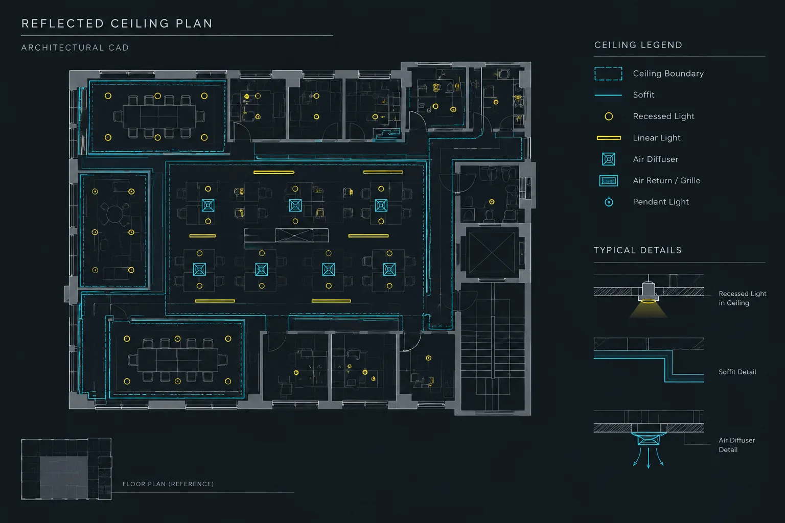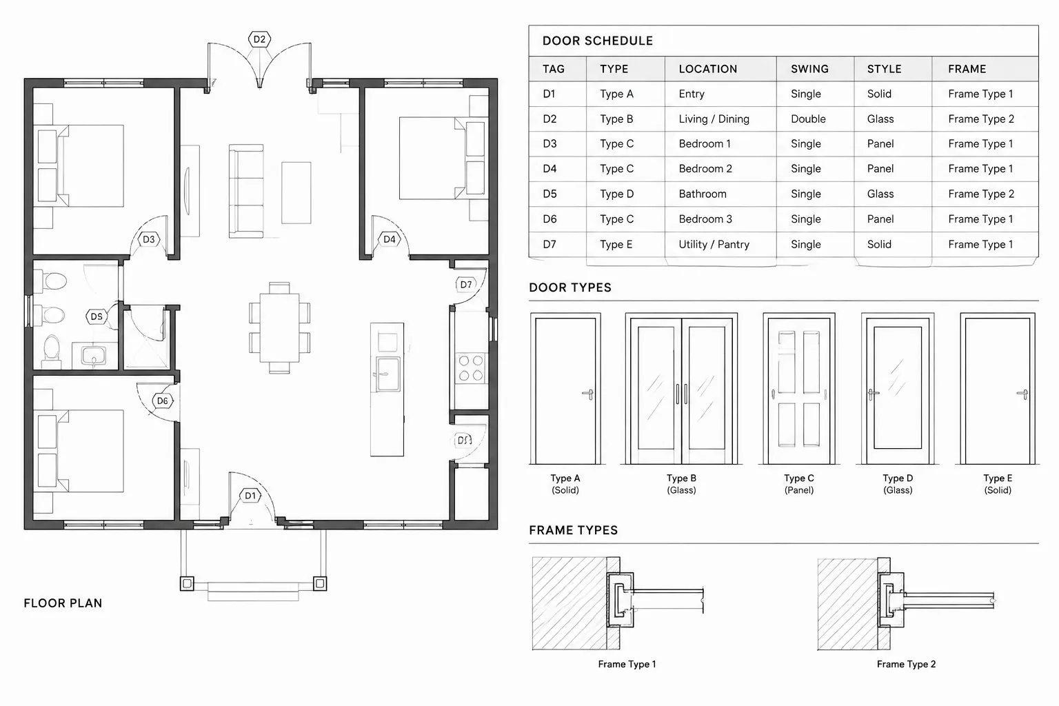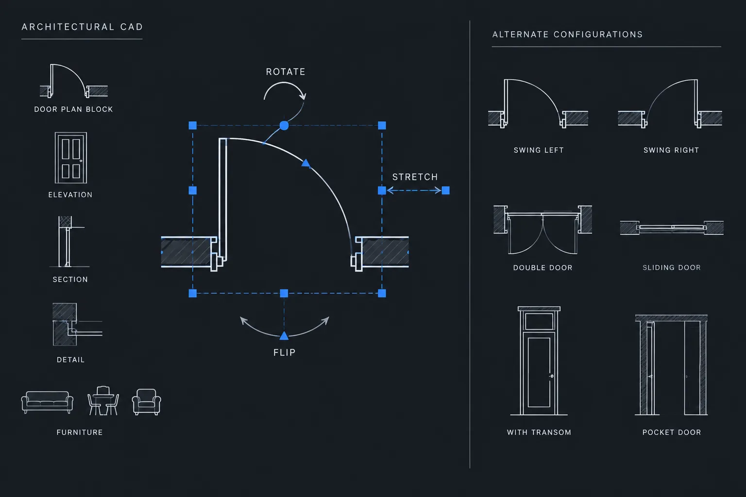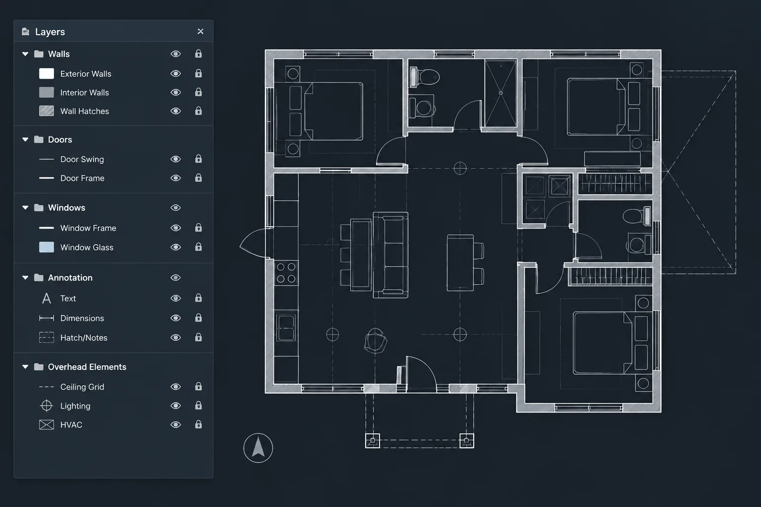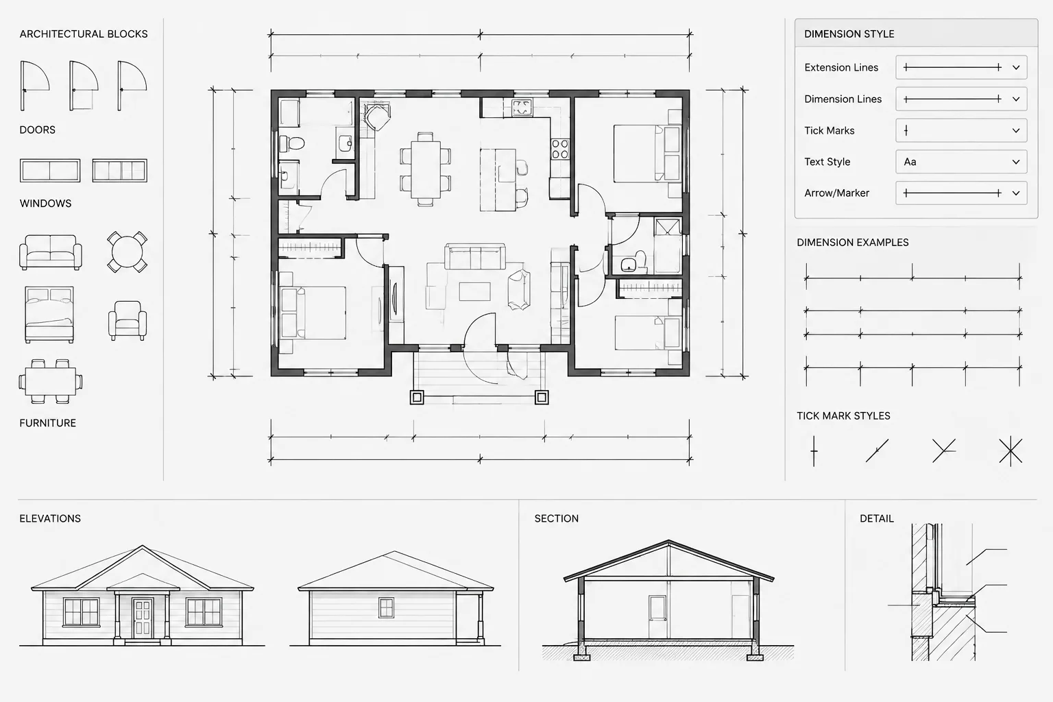
Architectural CAD dimension styles provide the shared rules behind dimension text, symbols, units, spacing, and plotted scale. When those rules are coordinated, dimensions remain visually consistent and easier to review across plans, enlarged views, and details.
This guide presents a practical setup and quality-control workflow for creating a controlled style family, diagnosing inconsistent dimensions, checking geometry association, and evaluating the final plotted result. It also explains why local overrides and imported styles should be reviewed before they become embedded in a project file.
Dimension styles control much more than the appearance of dimension text. In an architectural DWG file, they also influence symbols, extension lines, unit formatting, spacing, scale behavior, and the way dimensions respond when space is limited. A poorly managed style system can produce inconsistent sheets even when every measured value is correct.
A reliable dimension workflow begins by deciding how dimensions should look when plotted, how they will be scaled, and which variations the drawing set actually needs. The goal is not to create a separate style for every situation. It is to establish a small, predictable family of styles that supports plans, enlarged views, details, and other common architectural drawing types.
What an architectural dimension style controls
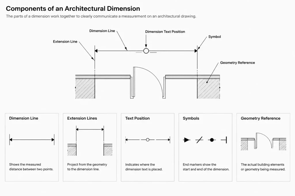
A dimension style is a collection of settings applied to dimension objects. Although the available controls vary by dimension type, the major groups are generally consistent.
- Dimension lines: Their color, linetype, lineweight, baseline spacing, and visibility.
- Extension lines: Their offset from measured geometry, extension beyond the dimension line, and suppression behavior.
- Symbols: Arrowheads, ticks, center marks, and other termination graphics.
- Dimension text: Text style, height, placement, alignment, gap, and movement rules.
- Fit behavior: What happens when text and symbols do not fit between extension lines.
- Unit formatting: The displayed unit format, precision, fraction treatment, zero suppression, rounding, prefixes, and suffixes.
- Scale behavior: Whether annotation is controlled through an annotative workflow or another planned scaling method.
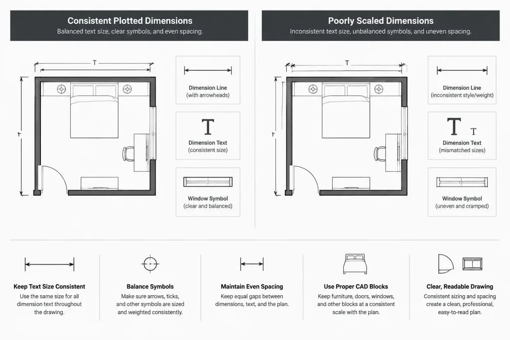
These settings should be evaluated as a coordinated system. Enlarging text without reviewing symbol size and text gaps, for example, can create crowded dimension strings.
Start with plotted appearance, not model-space appearance
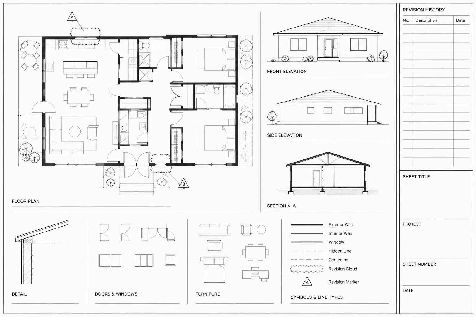
Architectural annotation should be designed around the final sheet. A dimension that looks comfortable while zoomed into model space may be unreadable or visually dominant when plotted. Before creating a style, determine the intended sheet appearance of its text, symbols, lineweights, and spacing.
Use a representative test sheet containing a floor plan, a short dimension, a long dimension string, fractions where applicable, and a congested condition. Plot or publish the test using the project’s actual sheet and plot configuration. Screen appearance alone is not a dependable quality-control method.
The test should answer practical questions:
- Is the dimension text legible beside room tags and general notes?
- Are arrowheads or ticks visually balanced with the text?
- Can extension lines be distinguished from walls, fixtures, and hatch patterns?
- Do closely spaced dimensions remain understandable?
- Does the style work in both open and crowded areas?
Choose one deliberate scale strategy
Dimension problems frequently occur when a file mixes scaling methods without clear rules. Two drawings can use the same text height setting and still plot differently if their dimension scale behavior is not coordinated.
Annotative dimension styles
An annotative style is intended to maintain a consistent plotted appearance across assigned annotation scales. This can be useful when dimensions remain in model space and the same drawing geometry appears at different viewport scales.
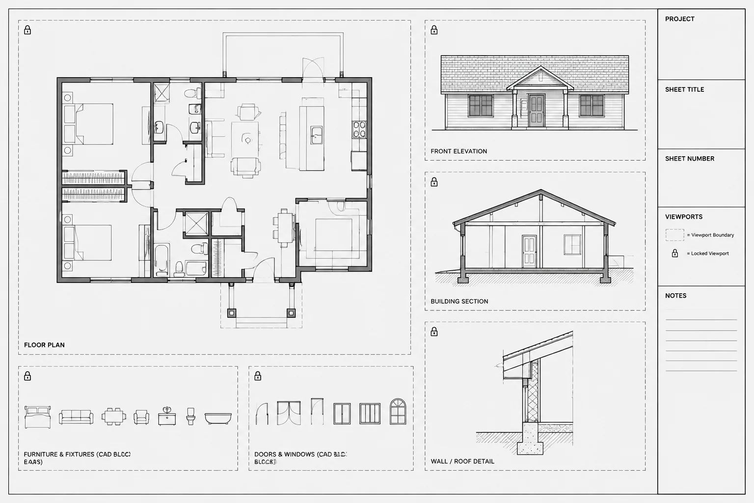
The workflow still requires discipline. Each dimension must have the appropriate annotation scale context, and users should avoid adding unnecessary scales to objects. Before issuing a sheet, inspect dimensions through the actual viewport rather than assuming that an object visible in model space will appear correctly everywhere.
Non-annotative dimension styles
A non-annotative workflow can also be reliable when the project team consistently manages dimension scaling. This approach may use styles prepared for particular drawing scales or dimensions placed in a controlled paper-space environment.
The important issue is consistency. Do not compensate for an incorrect setup by changing individual text heights, enlarging arrowheads, or applying arbitrary object scale factors. Those local corrections hide the underlying problem and make later revisions harder to manage.
Build a parent style before creating variations
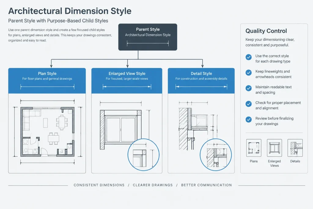
Create one parent architectural style containing the office or project defaults. Establish the text style, line properties, symbol type, extension-line behavior, unit display, and scale method there. Test it before developing additional styles.
When a legitimate variation is needed, derive it from the parent style instead of rebuilding it from scratch. Useful variations might include:
- A style for typical plan dimensions.
- A style for enlarged plans or details.
- A continuation or baseline condition with adjusted spacing.
- A special-purpose style for a different documented unit format.
Keep the family small. Names should identify purpose rather than a particular user, temporary revision, or unexplained abbreviation. A style called “New Dim Copy” gives the next drafter no useful information.
Coordinate the dimension text style
The text style referenced by a dimension style should align with the broader annotation system. Check its font selection, width behavior, oblique settings, and height configuration. If a fixed text height is embedded in the text style, it can limit how the dimension style controls text size.
A common source of inconsistency is using visually similar but technically different text styles across dimensions, leaders, room tags, and notes. The differences may be subtle on screen but become visible in published PDFs. Consolidating duplicate text styles reduces file clutter and makes global updates more predictable.
Use object properties and overrides carefully
A dimension can appear different from its assigned style because an individual property has been overridden. Overrides are sometimes justified, but they should not become the normal way to fix layout problems.
Before creating an override, determine whether the issue is:
- A one-time graphic conflict requiring text repositioning.
- A recurring condition that deserves a defined child style.
- An incorrect annotation scale or viewport setup.
- A dimension attached to the wrong style.
- A manual text replacement hiding the measured value.
Manual text replacement is especially risky. A dimension may look correct while no longer reporting the underlying measurement. If custom wording is necessary, preserve the measured value when possible and place explanatory text around it rather than substituting an unverified number.
Maintain geometry association
Associative dimensions can update when the referenced geometry changes, but only when the relationship is maintained. Moving extension-line origins independently, exploding dimensions, or replacing geometry can break that connection.
After editing walls, openings, grids, or other measured elements, verify the affected dimension strings. Do not assume every dimension has updated simply because some values changed. Pay particular attention to copied details, imported consultant backgrounds, and geometry replaced during design revisions.
A dimension should also reference the intended design geometry. Snapping to a hatch boundary, furniture block, finish line, or nearby underlay can produce a plausible but incorrect value.
Recommended setup sequence
- Confirm drawing units. Verify how the model is drawn before configuring the displayed unit format.
- Define the annotation strategy. Decide where dimensions will live and how their plotted scale will be controlled.
- Prepare the text style. Remove unintended fixed-height behavior and coordinate it with other sheet annotation.
- Create the parent dimension style. Configure lines, symbols, text, fit, units, and scale behavior.
- Build a test condition. Include chained dimensions, tight spaces, varying measured lengths, and typical architectural geometry.
- Plot a test sheet. Review the result at the intended output size.
- Create only necessary variations. Name each style according to its drawing purpose.
- Add styles to the project template. Remove experimental and duplicate styles before distribution.
Dimension style audit checklist
| Audit item | What to verify |
|---|---|
| Assigned style | Dimensions use approved project styles rather than imported or temporary styles. |
| Text appearance | Font, size, alignment, and spacing are consistent on plotted sheets. |
| Symbols | Arrowheads or ticks match the intended architectural graphic convention. |
| Units | Format and precision suit the documented information without implying unsupported accuracy. |
| Scale | Dimensions display correctly through their actual viewports. |
| Overrides | Property and text overrides are identified and justified. |
| Association | Dimensions remain connected to the intended geometry after revisions. |
| Layer | Dimension objects are placed on the designated annotation layer. |
| Plot result | Lines, text, and symbols remain legible without overpowering the drawing. |
Common problems and likely causes
Dimensions plot at different sizes
Check for mixed annotative and non-annotative styles, incorrect annotation scales, object overrides, or imported styles with similar names. Compare properties rather than relying on visual inspection.
Text moves outside the extension lines unexpectedly
Review the fit settings and available space. Avoid forcing every condition into the same arrangement when a clear leader or intentional text move would communicate the dimension more effectively.
Values do not change after geometry edits
The dimension may have lost association, may reference different geometry, or may contain a manual text replacement. Reconnect or recreate the dimension and verify the displayed value.
Imported details introduce many styles
Copied DWG content often brings dimension and text styles with it. Inspect incoming details in a controlled file, map useful content to project standards, and purge unused definitions only after confirming they are not required.
A controlled style system improves the entire drawing set
Good architectural dimensioning depends on both placement and configuration. A carefully built style cannot correct a confusing dimension layout, but it can remove unnecessary graphic variation and make errors easier to detect.
Keep the style family limited, test it through real sheets, minimize overrides, and recheck dimensions after geometry changes. That approach creates DWG files that are easier to revise, coordinate, plot, and hand off to other members of the project team.
Separate style problems from dimensioning problems
A dimension can be technically configured correctly and still communicate poorly. Style settings control graphic presentation, but they do not decide what should be measured, which geometry should be referenced, or where a dimension string should be placed. Quality control should therefore examine both the style system and the drafting decision.
- Configuration issue: Text, symbols, units, line properties, or scale behavior differ from the approved setup.
- Placement issue: Dimension strings collide with notes, cross important geometry, or create an unclear reading sequence.
- Reference issue: Extension lines are associated with unintended geometry or have lost their connection after an edit.
- Content issue: A manual replacement, prefix, suffix, or note changes how the measured information is understood.
This distinction prevents teams from creating new styles to solve problems that should instead be corrected through placement, association, or drawing coordination.
Use a diagnostic order when dimensions look inconsistent
Randomly changing text height or symbol size can hide the cause of a problem. A more reliable review begins with the dimension object and moves outward through the drawing environment.
- Confirm that the object uses the intended project dimension style.
- Inspect the object for local property changes and manual text replacement.
- Check the referenced text style and its relevant settings.
- Verify the chosen annotation and scaling workflow.
- Review the dimension through the viewport in which it will be published.
- Compare the plotted or published result with the project’s approved test condition.
Following the same diagnostic order across a team makes troubleshooting more repeatable and reduces unnecessary style duplication.
Treat dimension styles as managed project resources
Dimension styles should be maintained with the same care as layers, text styles, symbols, and title-block information. Changes to a parent style can affect many objects, while imported content can introduce definitions that appear similar but behave differently.
Before distributing a template or handing off a DWG file, review style names, remove abandoned experiments where appropriate, and document the intended use of each approved variation. If a special condition repeatedly requires overrides, evaluate whether it represents a legitimate reusable style or a drawing-layout problem.
Review dimensions after coordination changes
Dimension quality control should not be limited to the initial setup. Revisions to walls, openings, grids, referenced backgrounds, viewports, or annotation placement can affect previously correct dimensions. A focused review after coordination changes should look for detached references, altered values, crowded strings, and dimensions that no longer describe the intended design element.
The final check should occur in the published sheet context. That is where line hierarchy, text legibility, nearby annotation, and viewport behavior can be evaluated together.
Frequently asked questions
Should every drawing scale have a separate dimension style?
Not necessarily. The required style family depends on the project’s scaling strategy and where dimensions are placed. Create a variation only when it serves a clear, repeatable purpose rather than compensating for an inconsistent setup.
Why does a dimension look different even though it has the correct style name?
The object may contain property overrides, use a different text style dependency, carry an unexpected annotation context, or display manual replacement text. Imported definitions with similar names can also have different internal settings.
Are dimension overrides always a drafting error?
No. A limited override may resolve a unique graphic conflict, such as repositioning text in a congested area. It becomes a management problem when overrides are routinely used instead of correcting the parent setup or defining a justified variation.
Why should dimensions be checked in a viewport?
The viewport shows the drawing under its intended sheet and scale conditions. Model-space appearance alone may not reveal plotting, annotation-scale, lineweight, or congestion problems that become evident on the sheet.
What should be checked after editing measured geometry?
Confirm that the dimension still references the intended geometry, that its displayed value responds correctly, and that the revised string remains readable. Copied details, replaced objects, and imported backgrounds deserve particular attention.
How should imported dimension styles be handled?
Inspect imported content in a controlled file, compare its styles with the project system, and map retained dimensions to approved definitions where appropriate. Do not remove imported definitions until confirming that required objects no longer depend on them.