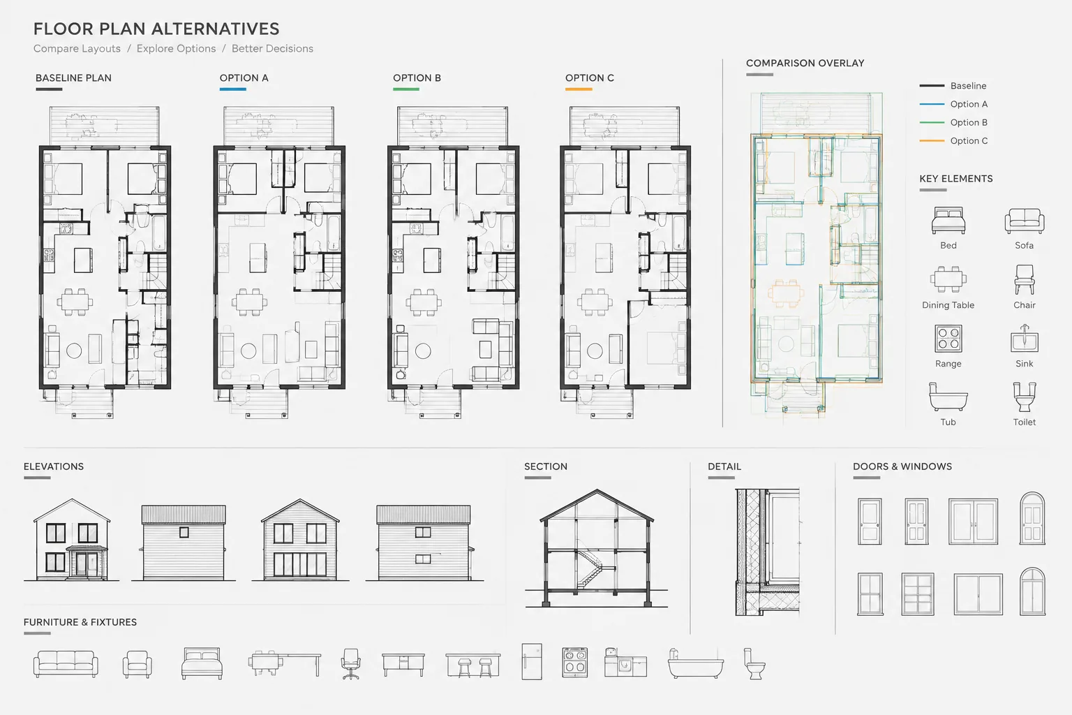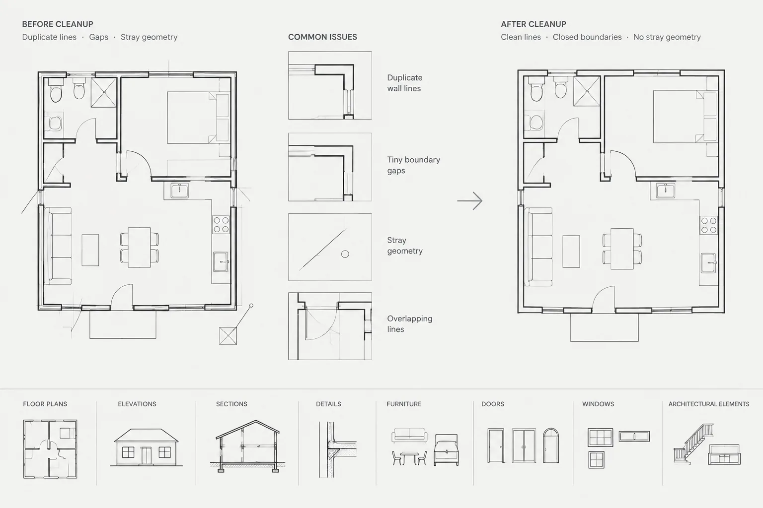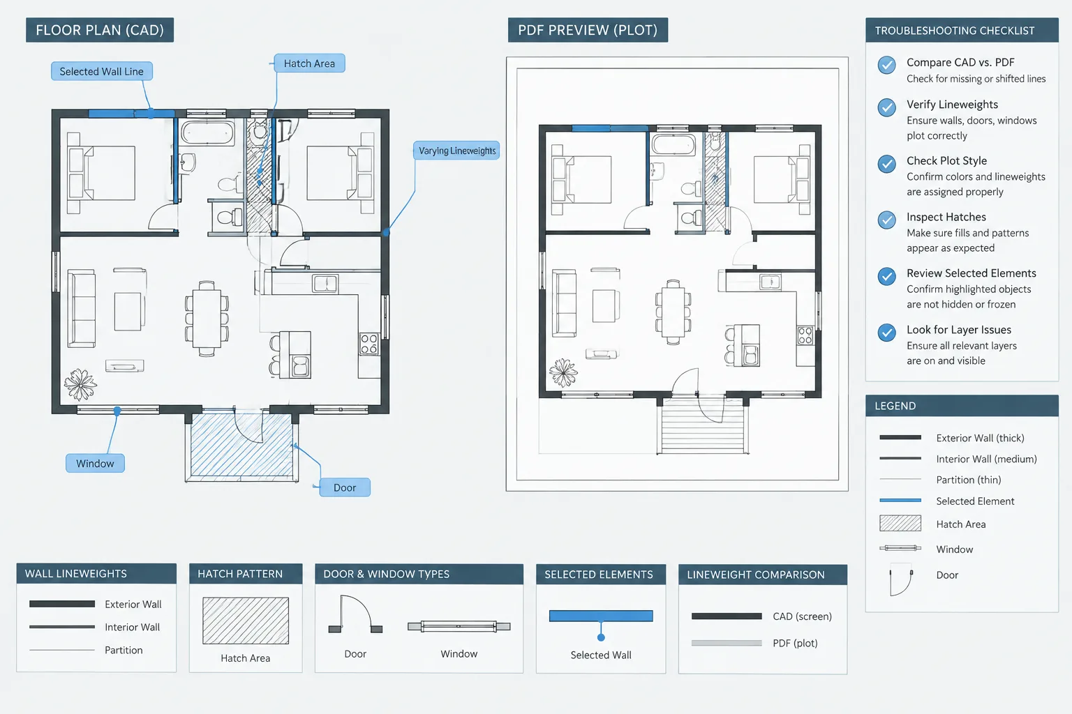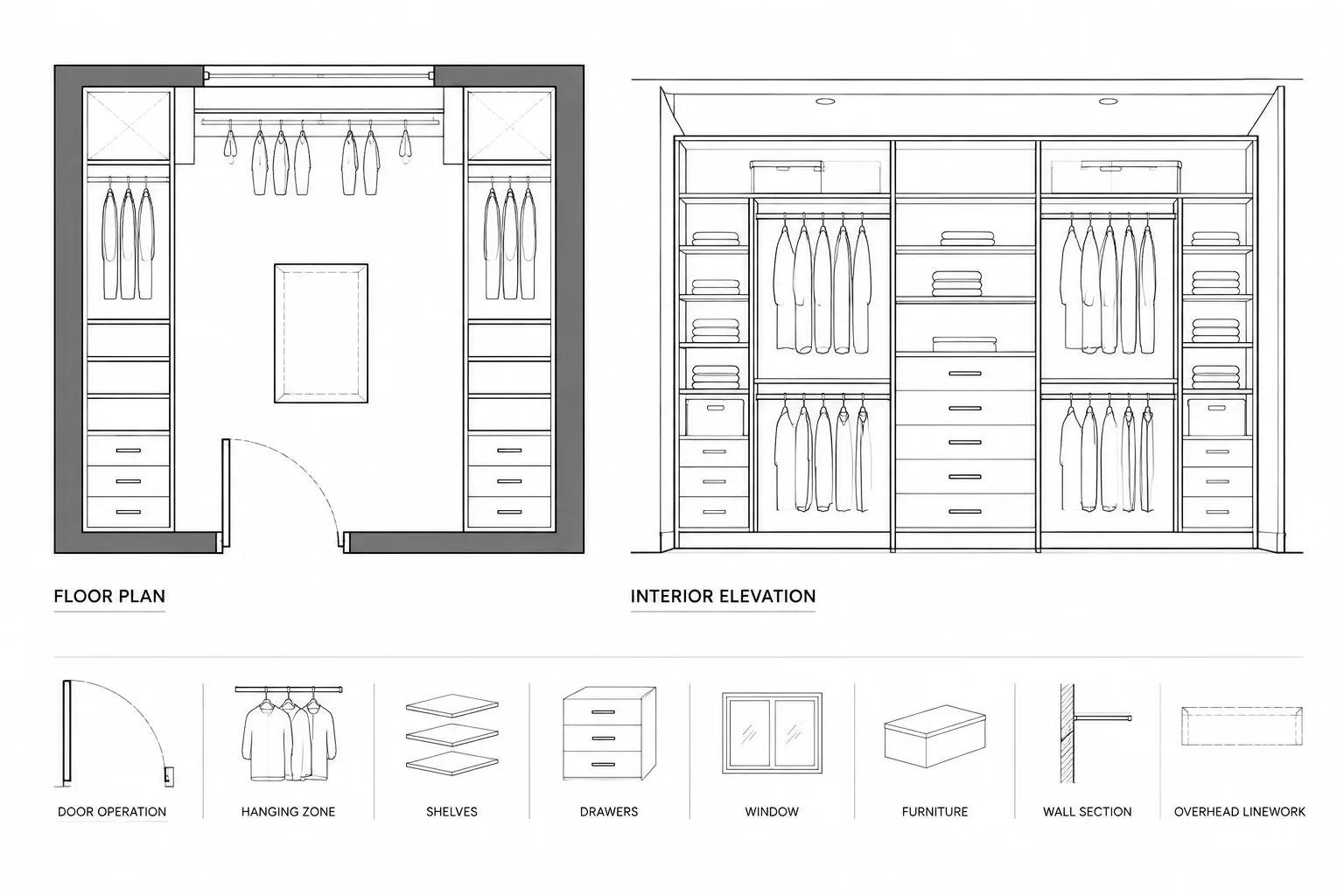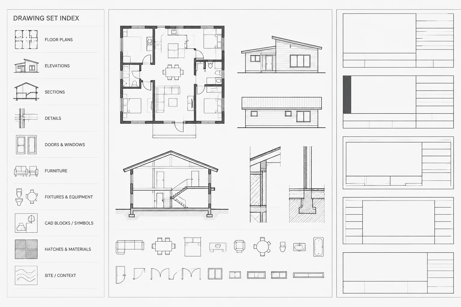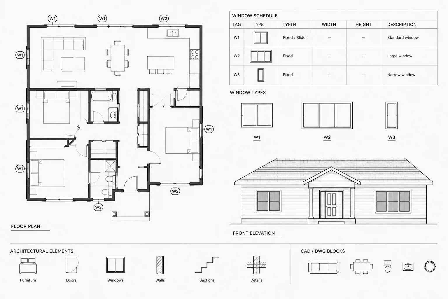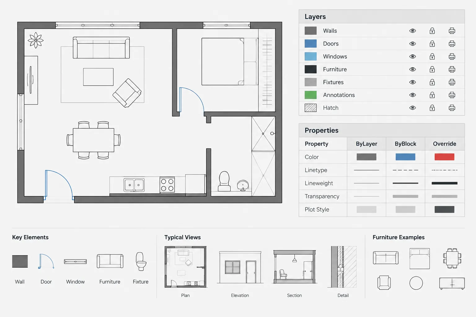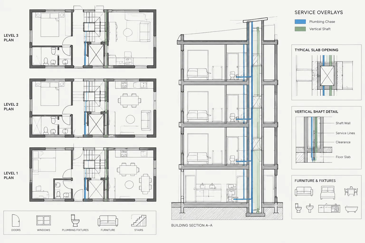
Drafting plumbing chases and vertical shafts requires more than boxing out space around service lines. The architectural CAD file must distinguish the enclosure, reserved service zone, structural opening, access location, and consultant information so that each element can be reviewed without being mistaken for another.
This guide explains a practical coordination workflow for developing chase and shaft graphics from early planning through drawing issue. It focuses on drawing organization, vertical alignment, view coordination, and responsibility boundaries rather than plumbing-system design.
Plumbing chases and vertical shafts often occupy little space on an architectural plan, but they can create major coordination problems when their boundaries, contents, and openings are not clearly documented. A chase that appears adequate during early planning may conflict later with structure, fixtures, access requirements, ceiling systems, or adjacent rooms.
The architectural drawing should not attempt to design the plumbing system. Its role is to establish coordinated enclosure geometry, reserve appropriate space, identify related openings, and communicate the design intent consistently across plans, sections, elevations, and consultant backgrounds.
Understand the Difference Between a Chase and a Shaft
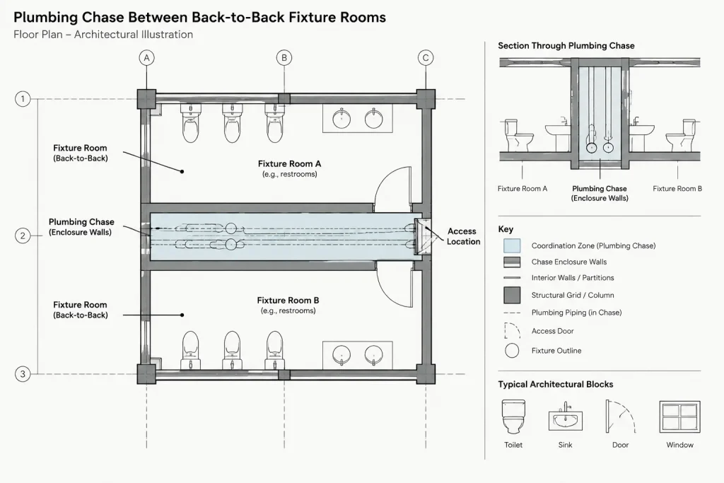
The terms are sometimes used loosely, so the project team should agree on what each label means. A plumbing chase is generally a concealed zone or framed enclosure used to route pipes and related components. It may be located behind fixtures, between rooms, or along a service wall.
A vertical shaft usually refers to a more continuous enclosure or opening extending through multiple levels. Shafts may contain plumbing, mechanical, electrical, or other building services. Their construction, access, continuity, and protection requirements depend on the project and applicable regulations.
Do not assume that every boxed-out wall area is a shaft or that every shaft requires the same construction. Confirm terminology, boundaries, ratings, access provisions, and system contents with the responsible project disciplines.
Begin with a Coordination Zone, Not a Finished Wall Detail
During early design, represent the required service area as a clear coordination zone before committing to exact partition faces. This lets the architectural and engineering teams evaluate whether the location works without creating false precision.
A useful early chase diagram may show:
- The approximate zone reserved for vertical and horizontal services
- Adjacent plumbing fixtures and equipment
- Structural grids, columns, beams, and slab edges
- Nearby doors, cabinets, and circulation paths
- Potential access locations
- The floors served by the vertical route
Keep this preliminary geometry on a clearly named working layer or in a coordination file. Do not let an unverified placeholder become indistinguishable from final wall construction.
Establish the Architectural Enclosure
Once the required service space has been reviewed, develop the enclosure as part of the architectural wall layout. Draft the wall faces according to the project’s wall-type system rather than drawing an isolated rectangle with no construction identity.
The enclosure should coordinate with surrounding finishes and room geometry. Check whether its walls align with adjacent partitions, tile surfaces, cabinets, fixture centerlines, or ceiling features. Small shifts can affect both appearance and usable space.
Separate Enclosure Geometry from Service Graphics
Architectural wall lines and consultant service graphics should remain distinguishable. Avoid tracing every pipe into the architectural model unless the project workflow specifically requires it. Instead, attach the current consultant file as an external reference and use controlled layers or display settings to show only the information needed for coordination.
If simplified riser symbols or service zones must appear in the architectural file, place them on dedicated layers. This allows them to be displayed for coordination and hidden from drawings where they would create clutter.
Coordinate the Chase on Every Affected Floor
A vertical route should be checked as a continuous stack, not as a separate shape on each floor. Overlay the relevant floor plans or compare them using a common project origin. Review the chase at every level it passes through, including roofs, intermediate floors, and levels where its contents change direction.
For each floor, verify:
- Whether the enclosure boundaries align vertically
- Whether structural framing crosses the intended route
- Whether the chase conflicts with doors, glazing, millwork, or equipment
- Whether adjacent fixtures remain correctly positioned
- Whether a slab or roof opening is required
- Whether access is shown where the design team requires it
- Whether the chase begins, ends, enlarges, or offsets at that level
An aligned stack is easier to coordinate, but alignment should not be forced when structural or planning conditions require an offset. When an offset occurs, document it in section or with a dedicated diagram rather than relying on disconnected plan graphics.
Represent Floor and Roof Openings Deliberately
The shaft enclosure and the structural opening are related but are not necessarily the same boundary. A wall may surround an opening, continue past a slab edge, or contain services that pass through smaller coordinated penetrations.
Use separate CAD objects and layers for architectural walls, opening extents, overhead or below-plane graphics, and consultant service information. This separation helps prevent a shaft wall from being mistaken for a slab opening during coordination or plotting.
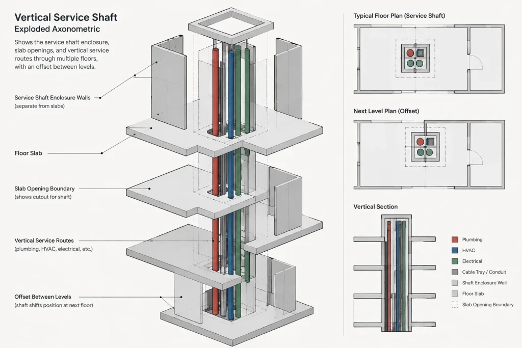
Opening geometry should be reviewed with the structural and engineering teams. Do not infer the required opening from the visible pipe layout alone. Supports, sleeves, clearances, construction tolerances, transitions, and other concealed components may affect the coordinated area.
Use Plans, Sections, and Enlarged Views Together
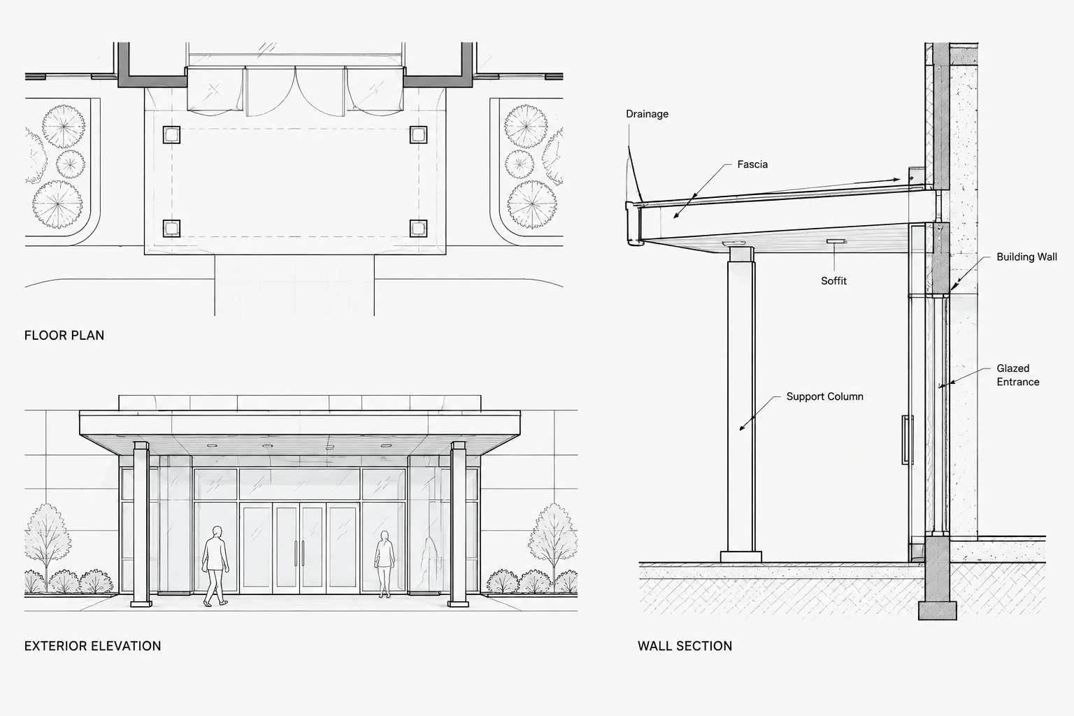
A floor plan communicates location and enclosure width, but it cannot fully explain vertical continuity. Add a section or enlarged view when the shaft changes direction, terminates, crosses complex framing, or interacts with ceilings and roofs.
A coordinated section can clarify:
- The levels served by the shaft
- Slab and roof relationships
- Offsets in the vertical route
- Changes in enclosure construction
- Access panel locations
- Connections to horizontal service zones
- Relationships with ceilings, soffits, and equipment
Keep plan and section references synchronized. If the shaft boundary moves in plan, review every related section, detail, opening diagram, and consultant background.
Label Chases and Shafts Consistently
Use a consistent identifier when multiple chases or shafts occur in a project. The identifier should connect plans, sections, enlarged views, and coordination records without implying unverified technical properties.
A simple coordination schedule can help track the design:
| Field | Purpose |
|---|---|
| Identifier | Connects the same chase or shaft across drawings |
| Levels served | Records where the vertical route begins and ends |
| Primary systems | Summarizes the intended contents for coordination |
| Enclosure reference | Points to the applicable wall type or detail |
| Opening status | Tracks whether structural opening geometry is pending or coordinated |
| Access status | Records whether access requirements have been reviewed |
This table is a project-management aid, not a substitute for engineering drawings or required construction schedules.
Control Graphics with Purpose-Built Layers
Layer names should follow the project CAD standard, but chase coordination typically benefits from separating several categories:
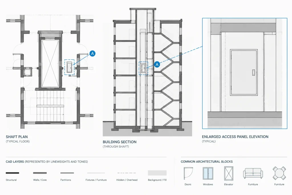
- Permanent architectural enclosure walls
- Preliminary coordination zones
- Floor and roof opening extents
- Overhead or below-cut-plane boundaries
- Chase and shaft identifiers
- Access panels and maintenance access graphics
- Consultant service overlays
Avoid placing all shaft-related objects on a generic wall layer. Separate layers make it easier to issue clean architectural plans while retaining useful coordination information in the working file.
Check Access Without Designing the Equipment
Concealed valves, cleanouts, dampers, controls, and other service components may require access. The responsible consultant should identify what must remain reachable, while the architect coordinates how that access affects partitions, finishes, cabinetry, and room appearance.
When an access panel is required, verify that it is not blocked by fixed furniture, equipment, shelving, mirrors, or doors. Coordinate its plan location with the relevant elevation because a panel that looks acceptable in plan may conflict with a finish pattern or wall-mounted item.
Review Project-Specific Construction Requirements
Shafts and penetrations may be affected by fire-resistance, smoke-control, acoustic, waterproofing, or other construction requirements. These conditions vary by building, location, system, and applicable regulations. Do not assign a rating, assembly, or penetration treatment based only on a downloaded CAD detail or a similar past project.
Use the project’s verified wall types, tested assemblies where required, consultant information, and approved specifications. CAD graphics should communicate the selected construction, not substitute for technical verification.
Run a Focused Coordination Check Before Issue
Before issuing the drawing set, isolate the chase and shaft layers and review them floor by floor. Then compare the architectural files with current structural and engineering references.
- Confirm that identifiers match across all views
- Check vertical alignment and documented offsets
- Compare enclosure faces with adjacent room layouts
- Verify that openings are shown on the correct drawings
- Review access locations in plan and elevation
- Check wall tags, section references, and detail callouts
- Remove obsolete preliminary zones and duplicate outlines
- Confirm that consultant references are current
- Plot a test sheet to verify line hierarchy and readability
The most reliable workflow treats plumbing chases and shafts as coordinated architectural spaces rather than leftover voids behind fixtures. Clear boundaries, disciplined layers, continuous vertical review, and well-managed references help the entire project team identify conflicts before they become construction problems.
Manage Changes and Coordination Status
Chase and shaft geometry often changes as fixture layouts, structural framing, service routing, and access needs are refined. A clear revision process helps prevent superseded boundaries or opening extents from remaining in the architectural drawings.
When a change is received, identify whether it affects the enclosure, the structural opening, the service route, or several related elements. Update only the information controlled by the architectural team, then flag dependent items for review by the appropriate consultant.
Distinguish Proposed, Reviewed, and Issued Information
Preliminary coordination zones should remain visually and organizationally separate from approved architectural construction. Layer controls, revision notes, drawing status records, or coordination markups can indicate whether geometry is proposed, under review, or incorporated into the current drawing set.
A useful change review should address:
- The source and date of the revised consultant background
- The affected floors, sections, elevations, and enlarged views
- Related wall types, room layouts, fixtures, and finishes
- Openings or penetrations requiring structural review
- Access locations requiring architectural coordination
- Obsolete graphics that should be removed or archived
Do not resolve conflicting backgrounds by silently selecting one version. Record the conflict, identify the responsible discipline, and keep uncertain geometry distinguishable until the team confirms the coordinated solution.
Use a Responsibility-Based Drawing Review
Good coordination depends on knowing which discipline owns each decision. The architect typically documents the enclosure and its relationship to rooms and finishes, while engineering and structural consultants provide system routing and opening requirements within their respective scopes.
Before incorporating consultant information, check that the reference uses the current project origin, floor relationship, and revision status. After incorporation, review the architectural consequences rather than merely confirming that the external reference displays correctly.
This responsibility-based approach keeps the CAD file useful without turning architectural graphics into an unverified substitute for engineering design, structural direction, specifications, or regulatory review.
Frequently Asked Questions
What should an architectural plan show for a plumbing chase?
The plan should clearly communicate the architectural enclosure, its relationship to adjacent rooms and fixtures, relevant identifiers, and any coordinated access or opening graphics. Service routing should come from the responsible consultant rather than being assumed from the enclosure shape.
Is a shaft boundary the same as a floor opening?
Not necessarily. The shaft boundary describes the enclosure, while the opening graphic represents the coordinated interruption or penetration through a floor or roof assembly. Keeping these elements separate reduces the risk of construction or coordination errors.
How should a preliminary chase be drawn?
Show it as a clearly identified coordination zone on a dedicated working layer. Avoid giving preliminary geometry the same appearance as verified wall construction, and replace or remove it when the enclosure is developed.
When is a section needed?
A section is especially useful when the route offsets, terminates, changes enclosure conditions, crosses framing, or connects with ceilings, roofs, and horizontal service zones. It should be coordinated with the corresponding plan references.
Should pipes be copied into the architectural CAD file?
Consultant service information is generally better managed through controlled references or dedicated coordination layers. Copying or tracing service graphics can create outdated duplicates unless the project workflow assigns a specific reason and responsibility for maintaining them.
Who verifies shaft ratings and penetration treatments?
Those requirements must be confirmed using the project-specific design criteria, consultant information, approved assemblies, specifications, and applicable regulations. A generic CAD detail should not be treated as verification.