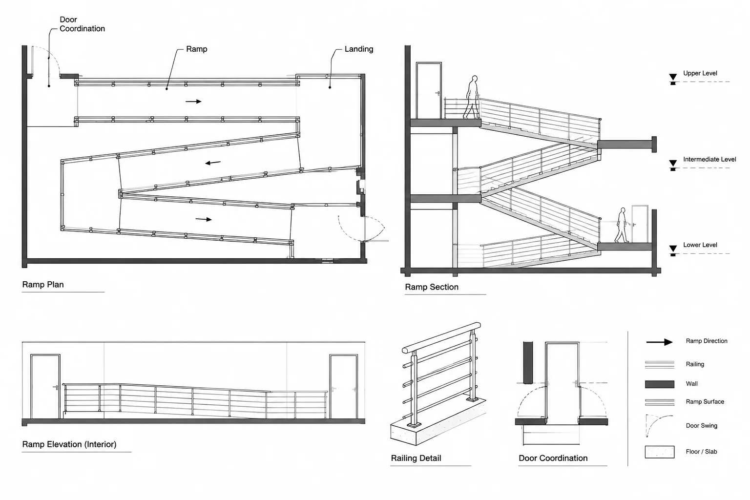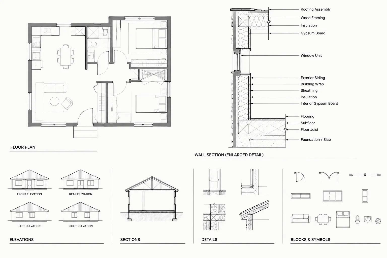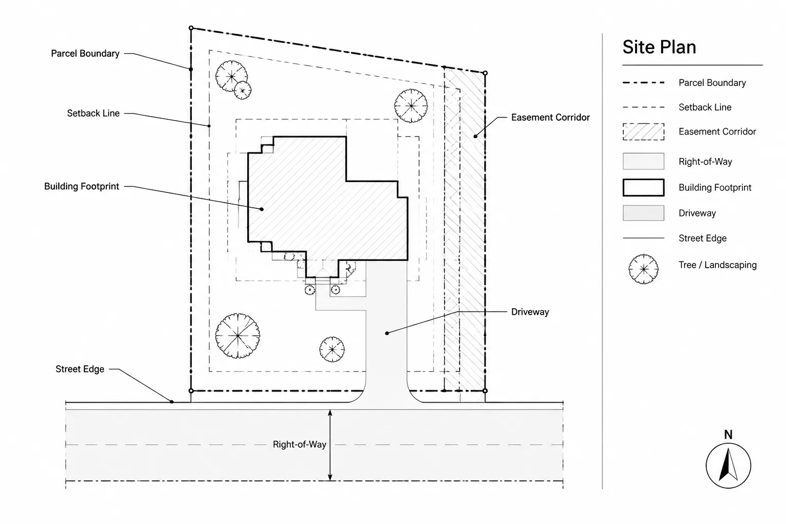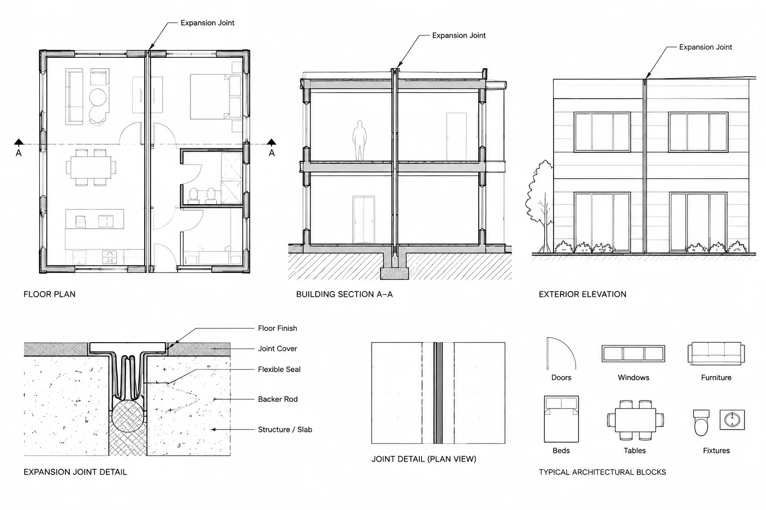
Drafting an expansion joint is not only a linework task. The joint must remain identifiable as it passes through plans, elevations, sections, finishes, ceilings, roofs, and enlarged details. A coordinated drawing set also needs to distinguish verified construction information from symbolic graphics and unresolved design criteria.
This guide explains how to draft expansion joints in architectural CAD while maintaining alignment, graphic clarity, and dependable references between sheets. It focuses on documentation workflow rather than prescribing joint dimensions, assemblies, or performance requirements, which must be established for the specific project.
Expansion joints can affect nearly every architectural drawing type, yet they are easy to document inconsistently. A joint may appear correctly on the floor plan but disappear from the reflected ceiling plan, exterior elevation, finish plan, or enlarged detail. It may also be mistaken for a simple material seam when its actual purpose is to accommodate movement between building portions.
A reliable CAD workflow treats an expansion joint as a coordinated building condition rather than a pair of parallel lines. Its location, identification, assembly, and relationship to finishes must remain traceable across the drawing set. The exact joint width, required movement, fire-resistance provisions, weather protection, and product selection should always come from the project design criteria and appropriate consultants—not from a generic CAD block.
Start by Confirming What the Joint Represents
Project teams may use several terms for intentional separations, including expansion joint, movement joint, control joint, isolation joint, and seismic joint. These terms are not automatically interchangeable. Their meaning may also vary by material, discipline, or office convention.
Before drafting, confirm the condition with the architect and relevant structural, civil, envelope, interior, or specialty consultants. At minimum, identify:
- Why the separation is required.
- Which building elements are interrupted.
- Whether the joint continues through multiple stories.
- Whether it crosses exterior walls, roofs, floors, ceilings, or occupied spaces.
- Which discipline controls its location and movement criteria.
- Whether a proprietary cover or weatherproofing assembly is expected.
- Which drawings and schedules must reference it.
Do not determine a joint width by measuring a schematic PDF or copying an unrelated detail. Use verified project information and retain a clear record of its source.
Create a Consistent Plan Representation
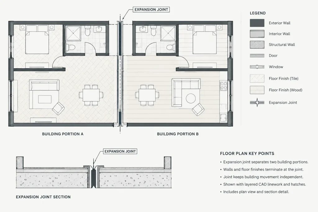
In plan, an expansion joint usually needs to communicate a continuous separation between building portions. Its graphic treatment should remain visible at the intended plot scale without overpowering walls, doors, dimensions, and room information.
Draw the physical edges accurately
Use separate linework for the actual edges of construction where they are known. Avoid representing the entire condition with one symbolic line if doing so makes wall returns, finish terminations, or floor openings ambiguous. The joint may change appearance as it passes through different wall types, but its controlling path should stay coordinated.
Add a symbolic identifier
A centerline, break symbol, tag, or other office-approved graphic can help readers follow the joint through a complex plan. Keep the symbol separate from physical construction lines so it can be controlled independently by layer, plot style, or viewport.
Check both sides of the separation
Architectural elements should not unintentionally bridge a movement joint. Review walls, floor finishes, casework, ceilings, handrails, equipment, and fixed furnishings that cross or terminate near it. A continuous CAD line is not merely a graphic issue if it implies a rigid connection that the design does not intend.
Coordinate the Joint Across Drawing Types
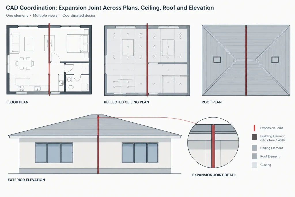
The joint should be reviewed wherever the affected construction appears. A useful method is to maintain a small coordination matrix during documentation.
| Drawing type | Items to review | Common CAD problem |
|---|---|---|
| Floor plan | Walls, openings, columns, floor edges, circulation, and dimensions | The joint stops at a wall or shifts between plan areas |
| Reflected ceiling plan | Ceiling systems, grids, soffits, lighting, and ceiling-mounted devices | The ceiling grid continues across the separation without review |
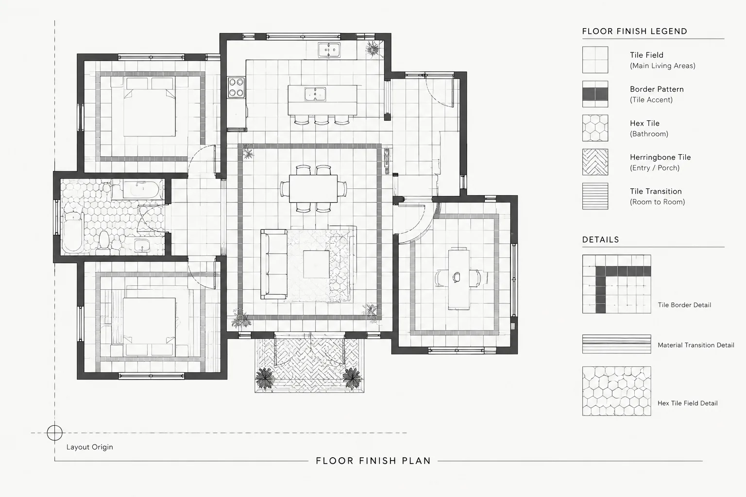
| Floor finish plan | Finish fields, patterns, transitions, and joint covers | Hatches conceal the joint or imply uninterrupted finish |
| Roof plan | Roofing zones, curbs, drainage, parapets, and cover assemblies | The plan omits the weatherproofed continuation |
| Elevation | Cladding modules, reveals, openings, and vertical continuity | The joint does not align with the plan or section |
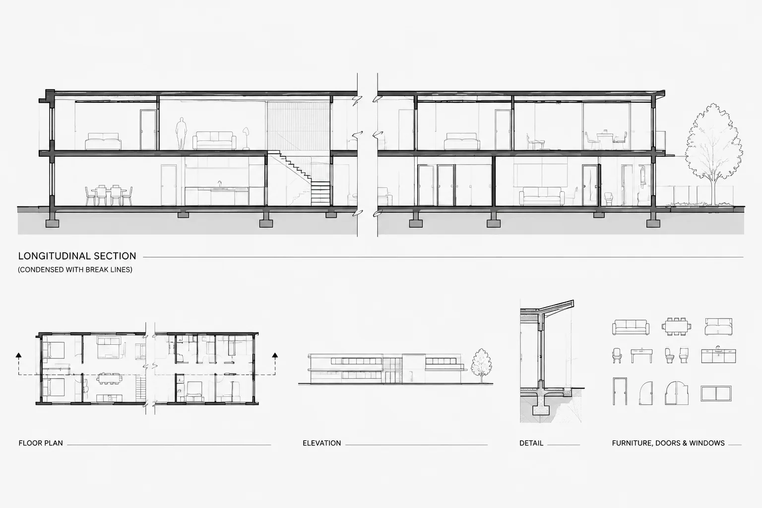
| Building section | Structure, slabs, walls, roof, ceilings, and foundations | One or more systems appear to bridge the separation |
| Enlarged detail | Substrates, covers, seals, membranes, and finish terminations | A generic assembly conflicts with project movement criteria |
This matrix does not replace technical design. It is a drafting check that reveals where information is missing or contradictory.
Use a Clear Layer Strategy
Keep joint graphics organized so physical edges, symbolic lines, tags, and hatches can be adjusted without editing unrelated building geometry. The exact layer names should follow the project CAD standard, but it is useful to distinguish among:
- Visible joint or opening edges.
- Overhead or below-cut joint conditions.
- Joint symbols and break graphics.
- Joint tags and reference notes.
- Detail components and sealant graphics.
- Temporary coordination or review marks.
Avoid placing the complete joint on a general wall layer. That makes it difficult to manage graphic hierarchy and increases the risk that a layer state will hide necessary information. Temporary review geometry should also remain non-plotting and should not be confused with issued construction linework.
Reference Rather Than Overload the Plan
The overall plan should show the joint location and provide a dependable route to additional information. It generally should not attempt to depict every cover plate, membrane turn, fastener, or substrate condition at a small scale.
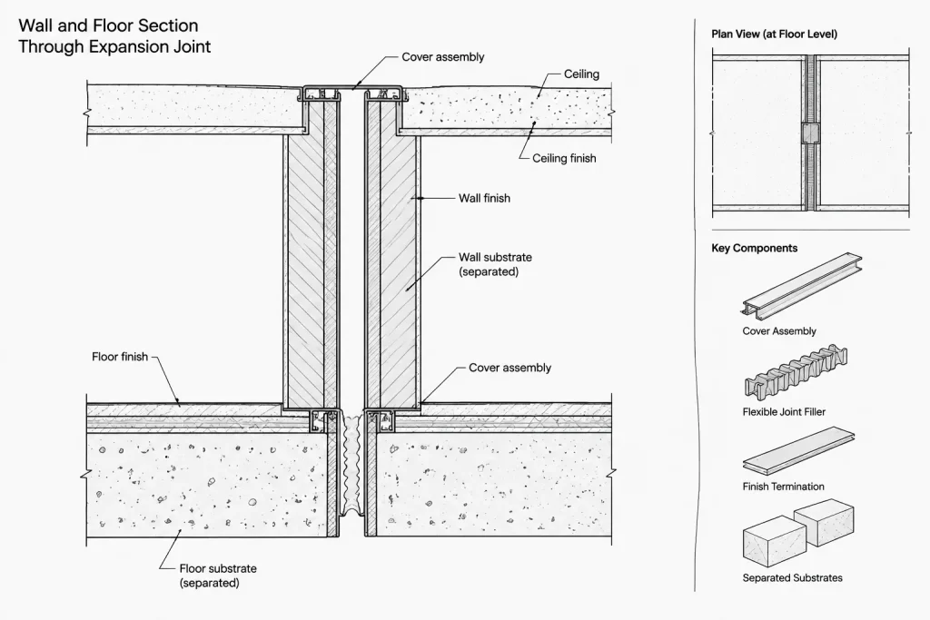
Use a consistent joint identifier where multiple joint types or assemblies occur. That identifier can point to a detail, schedule, keyed note, or specification reference according to the office documentation system. Keep the terminology identical across plans and details. A tag labeled as an expansion joint on one sheet should not become an unnamed reveal or miscellaneous break on another.
Place callouts where they can be read without masking the joint. Leaders should terminate clearly at the intended condition, especially where several finish joints and construction joints occur close together.
Draft Sections Through the Full Assembly
A section should explain what separates, what continues, and how adjacent finishes terminate. Begin with the main substrates and building elements rather than the decorative cover. Then add the project-specific components needed to resolve the condition.
Depending on location and design, coordination may involve:
- Structural edges on each side of the joint.
- Wall framing and sheathing terminations.
- Exterior cladding returns or cover assemblies.
- Air, water, vapor, or roofing control layers.
- Interior floor, wall, and ceiling finishes.
- Fire or smoke-related components where required by the project design.
- Transitions at parapets, curbs, corners, and changes in plane.
Do not add performance labels simply because they appeared in a library detail. Confirm every rated, waterproof, or movement-related requirement for the actual project. Generic details are useful starting references, but they are not substitutes for coordinated design.
Manage Repetition Without Hiding Variation
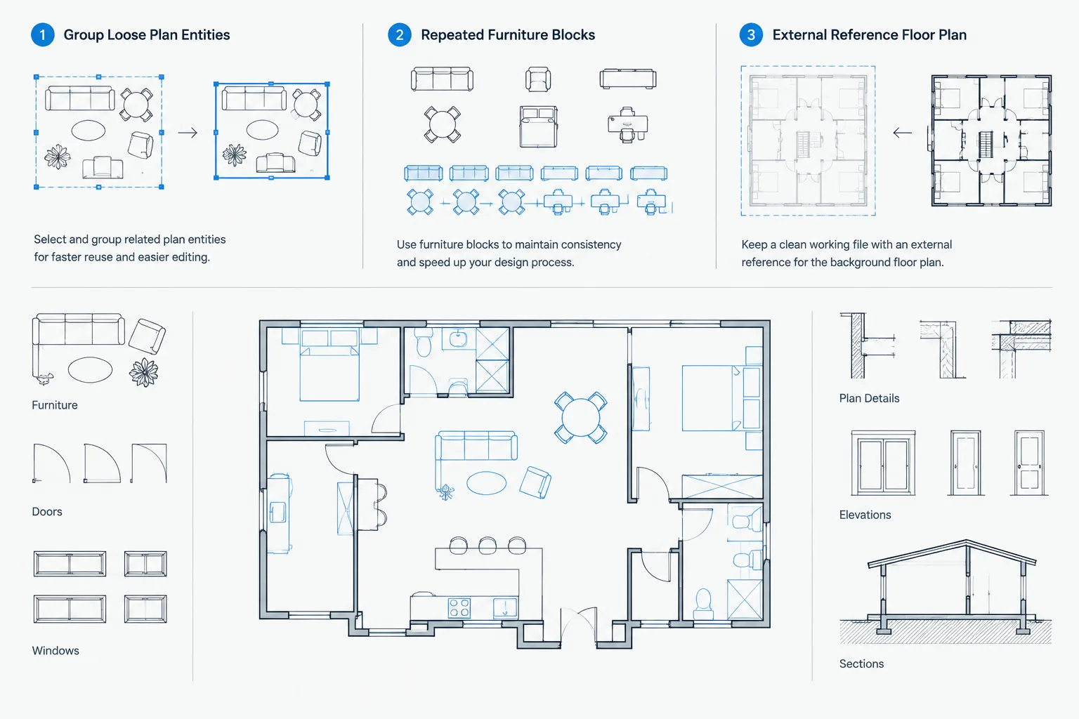
Reusable blocks can help standardize tags, break symbols, and detail-reference markers. However, the physical construction should usually remain editable enough to match each location. A single rigid block may conceal important differences between floor, wall, roof, and exterior conditions.
If a joint repeats through several levels, use externally referenced backgrounds or a shared control file to help maintain alignment. Check each level rather than assuming that stacked plans are identical. Building offsets, terraces, transfer conditions, and changes in envelope systems can alter the joint path.
Dimension the Location Carefully
Dimensions should allow the joint to be located without creating conflicting control points. Coordinate with the discipline responsible for establishing its position. Depending on the project, the location may relate to grids, structural edges, building geometry, or another verified datum.
Avoid dimension chains that make both sides appear fixed if movement must occur between them. Also avoid redundant dimensions that conflict when one drawing is revised. The joint opening itself should only be dimensioned where the project team has confirmed the value and the drawing is an appropriate place to communicate it.
Run a Focused Quality-Control Check
Before issue, isolate the relevant layers or use a temporary review color to trace the joint through the set. A practical review should ask:
- Does the joint follow the same location on every affected floor?
- Do plan, elevation, and section references agree?
- Are wall, floor, roof, and ceiling systems visibly terminated or coordinated?
- Do finish hatches stop or transition correctly?
- Are joint tags unique, readable, and linked to the correct details?
- Have doors, glazing, casework, fixtures, and equipment near the joint been reviewed?
- Do consultant backgrounds show a compatible location?
- Are generic notes or copied performance claims still present?
- Does the joint remain legible in the final plotted output?
Finally, inspect the plotted sheet rather than relying only on model-space display. Closely spaced lines may merge, dense hatches may obscure the separation, and a symbol that looks prominent on screen may become unclear at sheet scale.
Treat the Joint as a Set-Wide Coordination Element
The most effective CAD workflow begins with verified control information, separates physical and symbolic graphics, and traces the joint across every affected view. Plans establish location, elevations show visual continuity, sections explain assembly relationships, and details resolve local construction.
When information is incomplete, identify the condition for coordination instead of filling the gap with an assumed dimension or generic product detail. That approach produces cleaner DWG files and, more importantly, a drawing set that communicates where design decisions are still required.
Record Coordination Status Without Turning Assumptions Into Details
Expansion-joint documentation often develops while structural, envelope, interior, and specialty information is still being coordinated. CAD files should make that status understandable without presenting unverified information as final construction.
Use the project’s review process to distinguish confirmed geometry from open questions. Temporary marks, review clouds, or coordination notes should remain separate from issued linework and should identify the decision needed rather than propose an unsupported technical solution.
Maintain a clear source of control
For each joint condition, the team should be able to identify who controls its location, where the current criteria came from, and which views are affected by a revision. This is especially important when architectural backgrounds are shared with structural, envelope, ceiling, or interior drawings.
Review changes by condition, not only by sheet
When a joint moves or its assembly changes, search for every representation of that condition. Review tags, callouts, dimensions, finish boundaries, ceiling grids, elevation joints, section cuts, roof transitions, and detail references. Updating only the view where a revision began can leave the drawing set internally inconsistent.
Separate geometry from annotation
The physical opening, finish termination, symbolic path, identifier, and detail reference serve different purposes. Keeping them independently manageable makes it easier to adjust visibility and graphic hierarchy without shifting the controlling geometry.
Prepare the CAD File for Handoff
Before sharing or issuing the file, remove obsolete review graphics, check externally referenced backgrounds, and confirm that joint-related layers display correctly in the intended sheet views. Tags should remain readable, reference the correct condition, and use the same terminology throughout the set.
A clean handoff should allow another drafter or reviewer to trace the joint without reverse-engineering hidden linework or relying on unexplained CAD conventions. Any unresolved assembly, performance, or movement requirement should remain clearly identified for project-team resolution.
Expansion Joint CAD FAQ
Is an expansion joint the same as a control joint?
Not necessarily. Joint terminology can refer to different purposes and construction conditions depending on the material, discipline, and project convention. Confirm the intended function before assigning a tag or reusing a detail.
Should an expansion joint be drawn as a single line?
A symbolic line may help readers trace the joint, but it should not replace known physical edges when that would make openings, wall returns, or finish terminations unclear. Symbolic and physical graphics should be managed separately.
Which architectural drawings should show the joint?
Show or reference it wherever the affected construction must be understood. This may include floor plans, ceiling plans, finish plans, roof plans, elevations, sections, and enlarged details. The required views depend on the actual building condition.
Can a generic expansion-joint CAD block define the assembly?
No. A generic block can help standardize a symbol, tag, or reference marker, but it cannot establish project-specific movement, weather, fire, structural, or product requirements.
How should finishes be handled at the joint?
Finish boundaries, patterns, transitions, and cover conditions should reflect the coordinated design. Hatches should not conceal the joint or imply that a rigid finish continues across a separation without review.
Who determines the expansion-joint location?
Responsibility depends on the project and the reason for the separation. The architect should coordinate with the relevant structural, civil, envelope, interior, and specialty consultants rather than infer the location from an unverified background.
What is the best way to check joint coordination before issue?
Trace the condition through every affected view, compare consultant backgrounds, verify tags and references, and inspect the plotted sheets. This helps reveal shifts, missing continuations, obscured graphics, and copied notes that have not been confirmed.