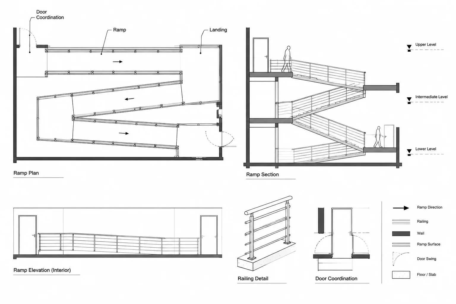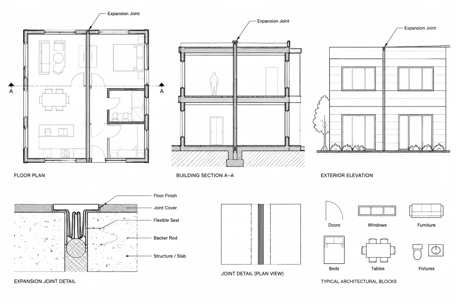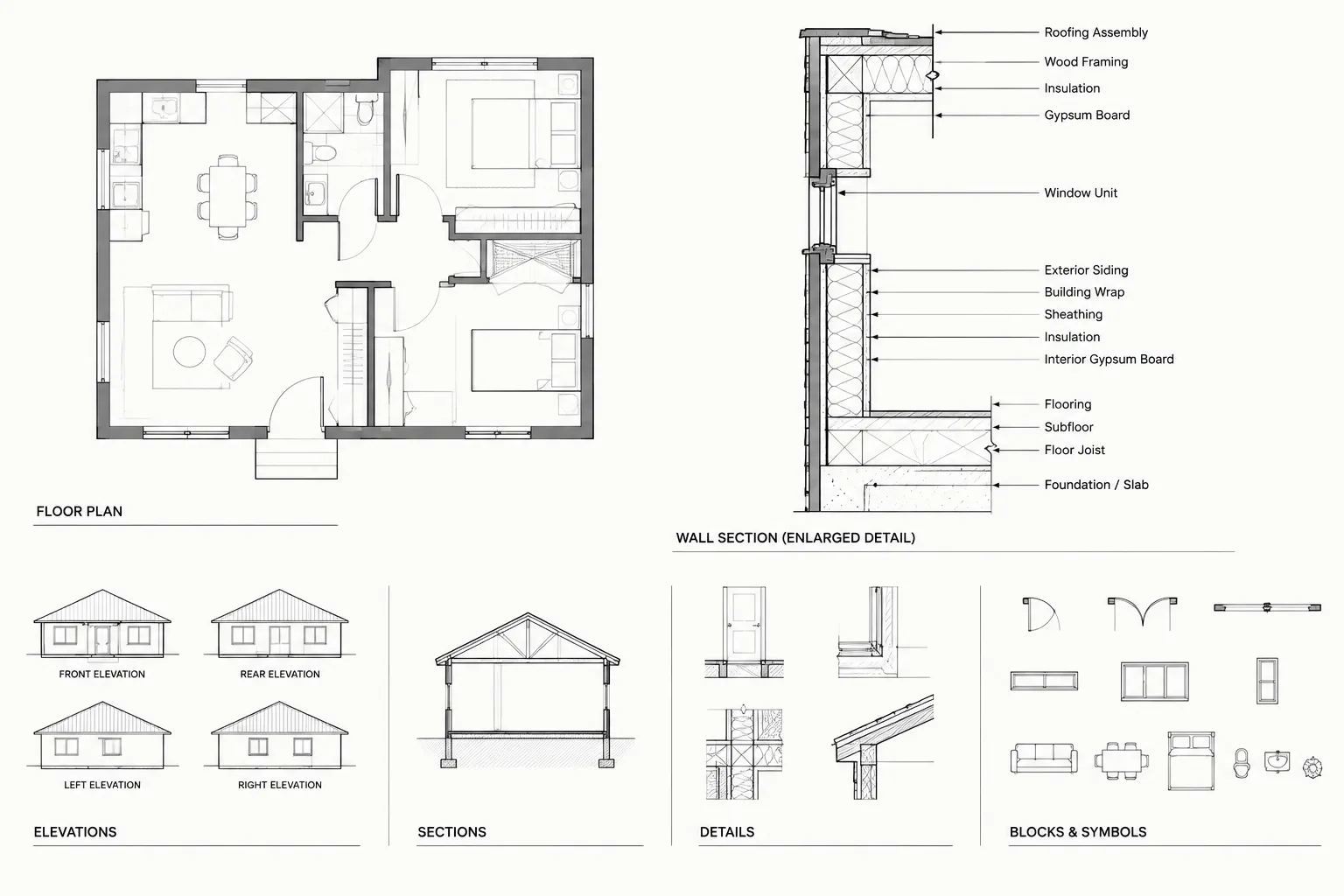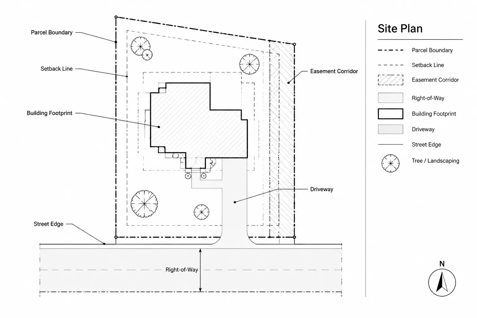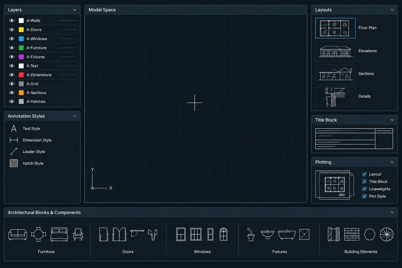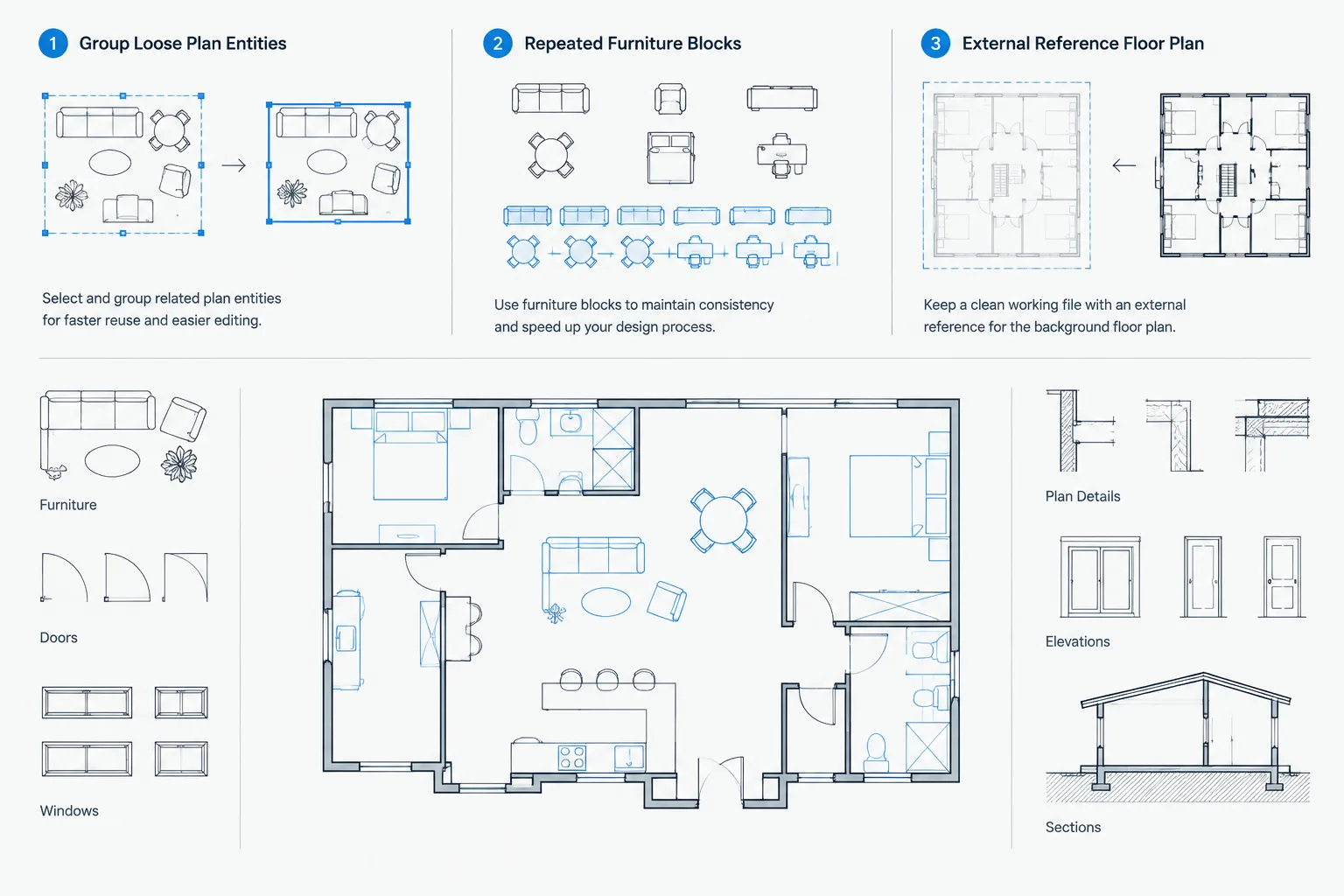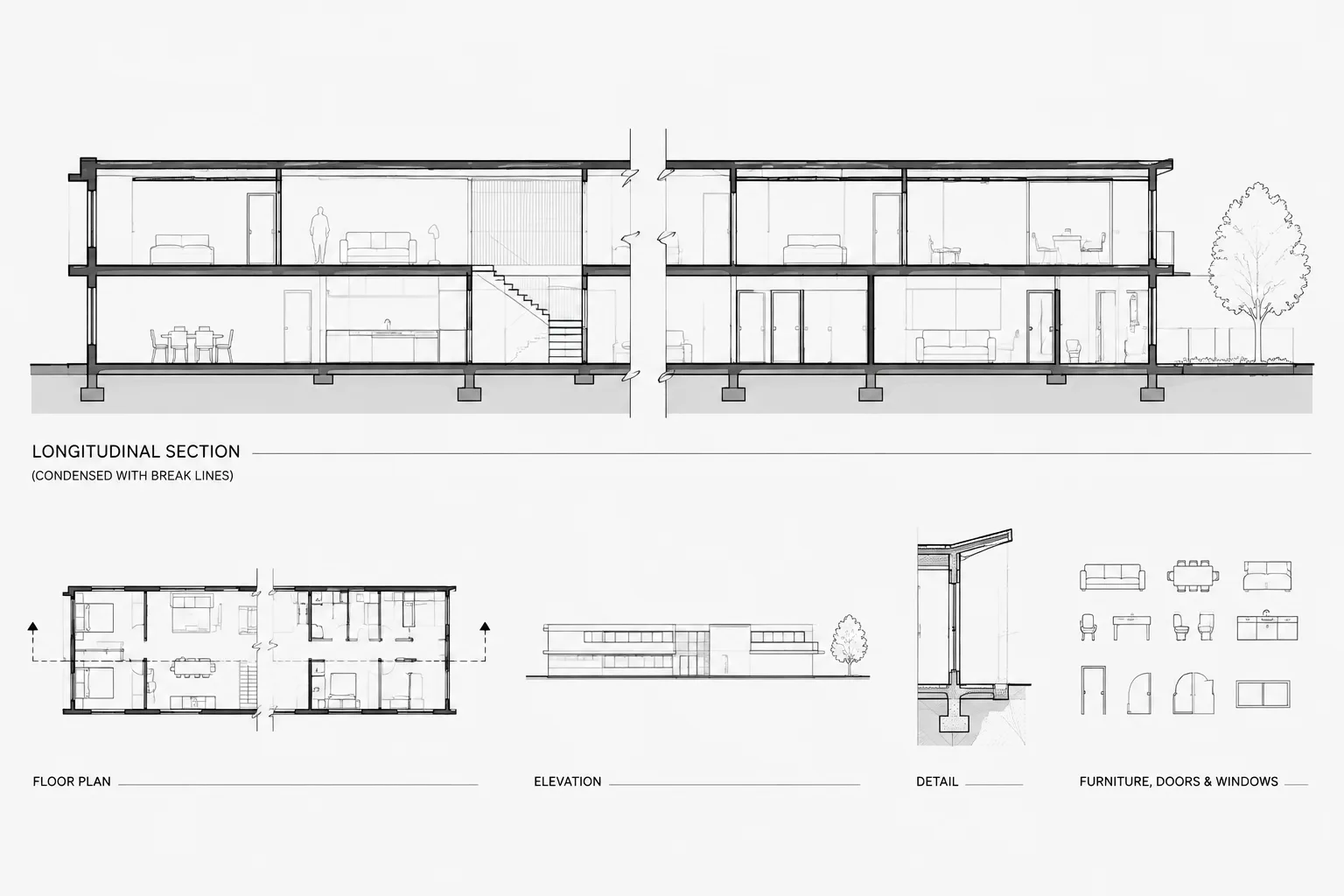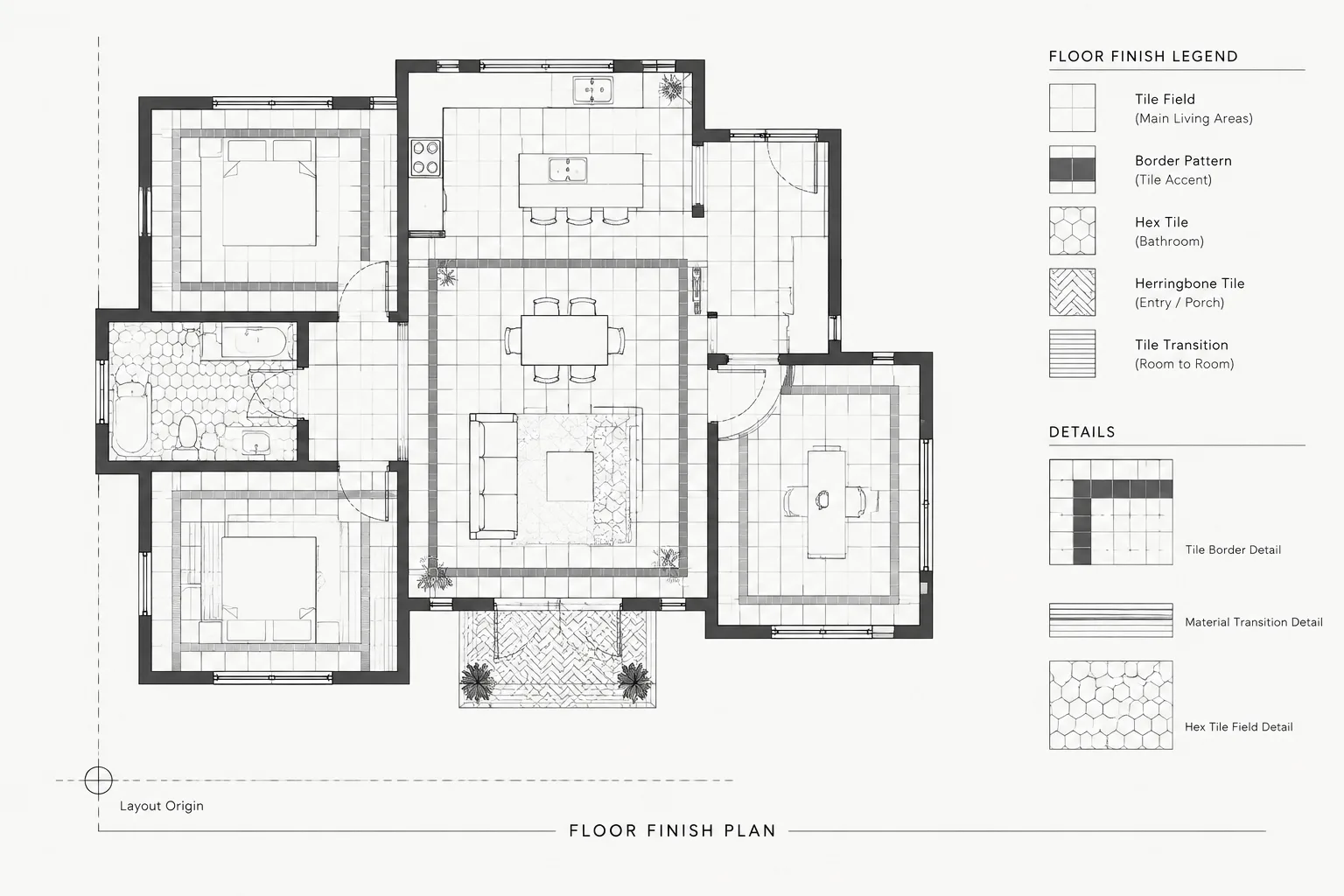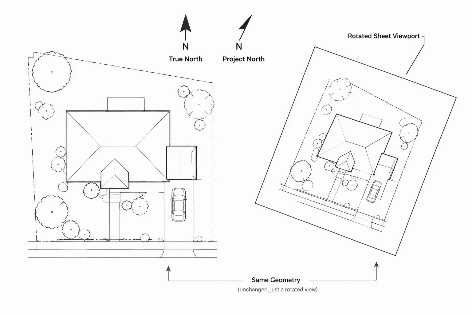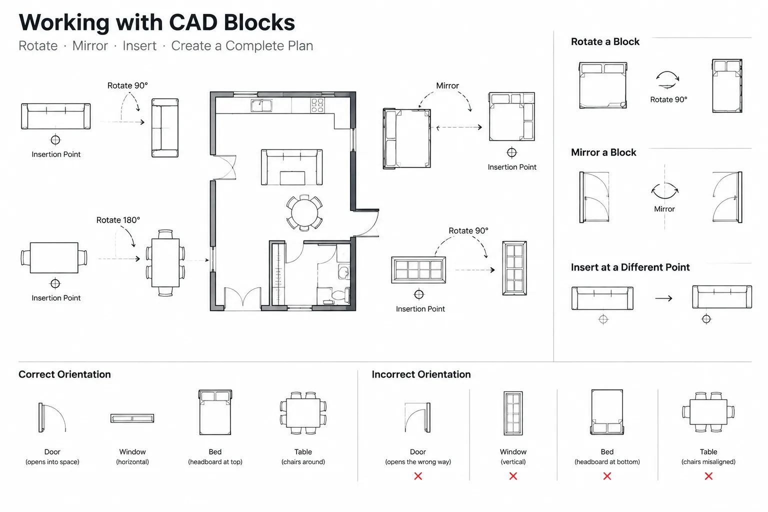
CAD block rotation and mirroring affect more than graphic appearance. A transformed block may also change handing, movement, viewing direction, access orientation, or the readability of its annotation.
This guide explains how to evaluate a block before transforming it, select an appropriate editing method, and review the result within an architectural drawing set. The goal is to preserve both visual clarity and the intended meaning of the block.
Rotating or mirroring a CAD block seems simple until the block contains text, attributes, asymmetric geometry, or information tied to a real-world orientation. A chair may mirror without consequence, while a door, plumbing fixture, directional symbol, or equipment block can become misleading when flipped carelessly.
A reliable workflow treats orientation as part of the block’s meaning, not merely its appearance. Before changing a block, determine which elements may rotate, which may mirror, and which must remain readable or coordinated with other drawings. This approach prevents reversed labels, incorrect handing, inconsistent symbols, and unnecessary duplicate blocks.
Why block orientation matters in architectural drawings
Architectural blocks represent several different types of information. Some are generic graphic objects, while others communicate direction, operation, or identity. The appropriate editing method depends on the type of block being placed.
- Symmetrical objects: Round tables, centered light fixtures, and similar objects may look unchanged after rotation or mirroring.
- Asymmetrical objects: Desks with returns, sectional sofas, sinks with offset bowls, and equipment with service sides require deliberate orientation.
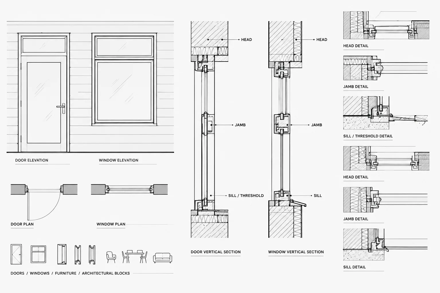
- Operational objects: Doors, gates, operable partitions, and access panels may use graphics that indicate movement or handing.
- Annotated symbols: North indicators, section marks, room-related symbols, and equipment tags may contain text or attributes that must remain readable.
- Manufacturer-specific objects: Product geometry may show controls, connections, access zones, or installation direction. Mirroring such a block does not necessarily create a valid opposite-hand product.
The visual result is therefore only one part of the review. A block can look plausible while communicating the wrong condition.
Inspect the block before transforming it
Start by selecting the block and identifying its insertion point, scale, rotation, layer, and attribute content. If it came from an external library, inspect it in an isolated working area before using it throughout the project.
Look for nested blocks, hidden layers, wipeouts, hatches, construction geometry, and text embedded inside the definition. Confirm whether the block is uniformly scaled and whether it was created in the same drawing units as the project. A transformation can expose problems that were not apparent in the original orientation, especially when nested content uses different base points or text settings.
Questions to ask during inspection
- Does the block represent a generic object or a specific product?
- Is its insertion point located at a useful placement reference?
- Does it include text, attributes, leaders, or directional symbols?
- Is any geometry intended to show operation, clearance, access, or connection?
- Will the object appear in schedules, quantity checks, or coordinated backgrounds?
- Are plan, elevation, and section representations related?
If the answers are unclear, avoid distributing transformed copies across the drawing until the block definition has been reviewed.
Use rotation for direction, not for correction
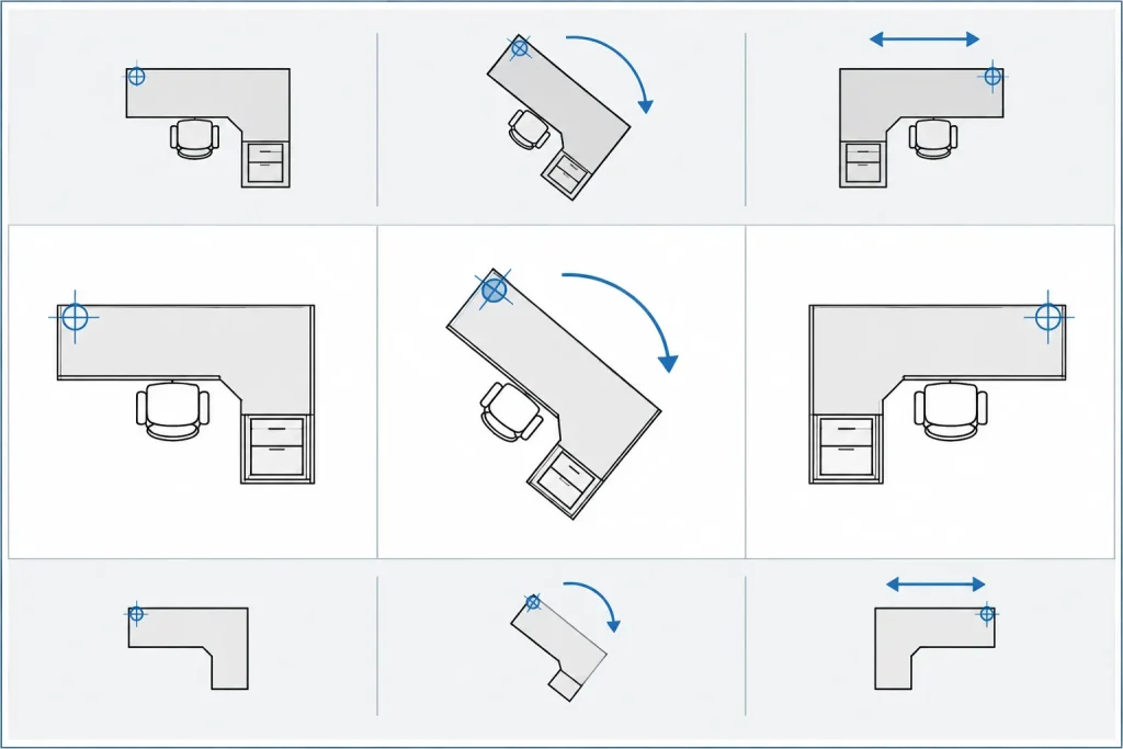
Rotation is generally the safest transformation because it preserves the relationship between the parts of a block. It is appropriate for furniture placement, fixture alignment, equipment orientation, and symbols designed to point toward a view or location.
Choose a meaningful base point when rotating. For furniture, this may be a corner, center, or wall-contact point. For a door, it is commonly the hinge-side reference represented by the block. For a directional symbol, the useful pivot may be the center of the marker rather than the edge of its text.
Avoid rotating a poorly constructed block merely to make it appear correct. If the base orientation is inconsistent with the rest of the library, correct the definition or establish a documented placement convention. Repeated corrective rotations make future replacement and quality control more difficult.
Keep annotation readable
Text inside a block may rotate with the geometry. That may be desirable for a directional label, but undesirable for an identifier that should read consistently on the sheet. Decide whether the annotation belongs inside the block at all.
When labels must remain horizontal or follow a project-wide reading convention, consider separating annotation from the graphic block. Another option is to create a carefully managed block definition in which the graphic and annotation components can be controlled independently. Test the result in both model space and plotted sheet views.
Understand what mirroring changes
Mirroring creates a reversed geometric condition. It is useful for layout studies and for genuinely opposite-handed generic objects, but it should not be treated as a universal shortcut.
A mirrored door symbol may describe the intended swing in a plan, yet the project team still needs consistent terminology for communicating that condition. A mirrored appliance or piece of equipment may show an arrangement that is not manufactured. A mirrored section symbol may reverse its directional meaning if its marker and view reference are not checked together.
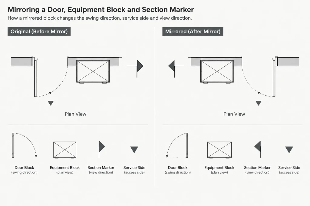
After mirroring, review more than the outline. Check arcs, swing indicators, leaders, text, attributes, hatch patterns, nested blocks, and any side identified for access or service.
| Block content | Typical concern after mirroring | Recommended check |
|---|---|---|
| Plain furniture outline | Incorrect functional orientation | Confirm use, circulation, and adjacent clearances |
| Door or gate | Changed swing or handing | Compare with room use, hardware information, and schedule references |
| Text or attributes | Reversed or awkward reading | Verify displayed values and plotted readability |
| Equipment | Invalid access, control, or connection side | Confirm against verified project information |
| Section or elevation marker | Direction no longer matches the referenced view | Trace the callout to its destination drawing |
| Nested block | Internal elements respond inconsistently | Open and inspect the complete block hierarchy |
Do not rely on display settings alone
CAD applications include controls that influence whether text appears reversed after mirroring. Such controls can improve readability, but they do not determine whether the resulting architectural condition is correct. A readable label does not validate a mirrored product, door handing, or directional marker.
Project templates should use a consistent approach to mirrored text. Changing a drawing-wide setting to solve one imported block may affect other content. Test the behavior in a temporary area, document the preferred setting, and inspect existing symbols before applying broad changes.
Choose between one flexible block and separate definitions
Not every orientation requires a separate block definition. Generic furniture and simple fixtures can often use one clean definition with rotation and mirroring applied to block references. This keeps the library compact and makes global updates easier.
Separate definitions are more appropriate when the variants represent meaningfully different conditions. Examples may include opposite operational arrangements, distinct product configurations, or symbols with different annotation. Naming should describe the condition rather than an arbitrary editing history. Names such as “copy,” “flipped,” or “new block” provide little value to another drafter.
Where adjustable block behavior is used, limit the available options to tested conditions. A block with many unverified states can be harder to coordinate than a small set of clearly named definitions.
Establish orientation conventions for the block library
A shared library works best when blocks have a predictable default orientation. Select a convention appropriate to each category and document it in the library notes.
- Place wall-mounted objects against a consistent reference edge.
- Orient door and gate graphics according to a documented base condition.
- Keep text in the library’s intended reading direction.
- Use insertion points related to placement rather than arbitrary drawing origins.
- Define whether equipment blocks show a front, service side, connection side, or control side.
- Provide plan and elevation blocks with compatible naming and orientation.
Preview images or small reference diagrams can help users understand the default condition before insertion. This reduces trial-and-error placement and discourages unnecessary block redefinition.
A practical placement and review workflow
- Insert a clean reference. Use the approved project or office library source rather than copying an unknown instance from another drawing.
- Confirm units and scale. Correct size problems before evaluating orientation.
- Place from the intended insertion point. Snap to the architectural reference that controls the object’s location.
- Rotate to the required direction. Use known drawing geometry such as a wall face or layout axis as the alignment reference.
- Mirror only when the reversed condition is valid. Do not assume that geometric reversibility means functional reversibility.
- Review internal content. Check text, attributes, swing graphics, controls, access zones, and nested symbols.
- Compare related documents. Review elevations, sections, schedules, equipment information, and consultant backgrounds where relevant.
- Plot a test view. Confirm lineweights, readability, and orientation at the intended sheet scale.
Quality-control checks before issue
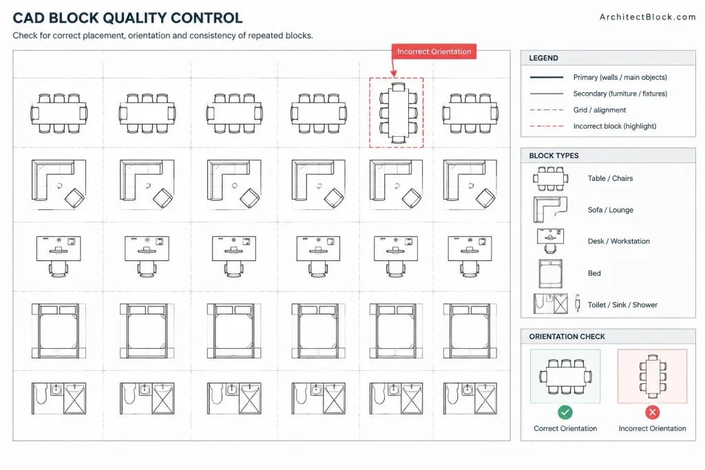
Use a focused review to find orientation errors that are easy to miss during drafting. Search for repeated blocks with unusual rotation or scale values, and compare similar rooms or layout modules for inconsistent placement. Inspect attributes for reversed alignment, duplicated identifiers, or labels detached from the object they describe.
Door and gate graphics deserve a dedicated review because their orientation affects plan communication. Directional callouts should be traced to the corresponding elevation or section. Equipment and fixture blocks should be checked against verified project information rather than accepted solely because they fit the available space.
Finally, distinguish drafting convenience from project verification. Rotating or mirroring a CAD block can create a useful graphic representation, but it does not establish product availability, code compliance, accessibility, structural suitability, or installation feasibility. Those matters require confirmation using the applicable project documents and qualified sources.
Build orientation into the drafting standard
Consistent block orientation reduces cleanup and improves coordination across an architectural drawing set. The most effective standard combines sensible insertion points, predictable default directions, readable annotation, clear naming, and a defined review process.
When a block carries operational or directional meaning, transform it deliberately and verify the result. When it is simply a generic graphic, keep the workflow efficient without creating unnecessary variants. This distinction produces cleaner DWG files and drawings that communicate more reliably.
A simple decision framework for transformed blocks
Before approving a rotated or mirrored block, separate its content into geometry, annotation, and project information. Geometry determines whether the object still depicts the intended arrangement. Annotation determines whether labels and attributes remain readable. Project information determines whether the transformed condition agrees with schedules, callouts, product data, and related views.
Rotation is usually appropriate when the entire object needs to face or align in another direction without reversing its internal relationships. Mirroring requires a more deliberate review because it creates an opposite geometric condition. If that opposite condition has a different operational meaning, product identity, or annotation requirement, a separately named and verified block definition may communicate the design more reliably.
Record intent instead of relying on appearance
A block library should make orientation choices understandable to someone who did not create the original definition. Clear default directions, meaningful insertion points, descriptive names, and consistent annotation behavior reduce the chance that another drafter will reinterpret a block incorrectly.
For project quality control, review transformed blocks in context rather than as isolated symbols. Check adjacent walls and clearances, related elevations or sections, schedule references, and plotted readability. A block that looks correct in plan can still conflict with another drawing or represent an unverified condition.
Frequently asked questions
Is rotating a CAD block safer than mirroring it?
Rotation generally preserves the internal relationship between the block’s components. Mirroring reverses that relationship, so it requires additional checks for handing, operation, annotation, access sides, connections, and directional meaning.
Why does text behave differently from block geometry?
Text may be embedded directly in the block, stored as an attribute, or nested inside another definition. Its response can also depend on drawing settings and how the block was constructed. Always inspect displayed values and plotted readability after a transformation.
Should annotation remain inside the block?
Keep annotation inside when it is an essential and consistently managed part of the symbol. Consider separate annotation when labels must follow a sheet-wide reading convention or need to move independently from the object geometry.
Can a mirrored block represent an opposite-hand product?
Not automatically. Mirroring proves only that the geometry can be reversed in the drawing. Product availability, controls, connections, access requirements, and installation orientation must be confirmed using verified project information.
When should separate block definitions be used?
Separate definitions are useful when orientations represent genuinely different operational, product, or annotation conditions. Use descriptive names that identify the condition rather than names based on editing history.
What should be checked after mirroring a door or directional symbol?
Review the swing or viewing direction, readable text, attributes, referenced destination, adjacent room conditions, and coordination with schedules or related drawings. Do not approve the result based only on its outline.