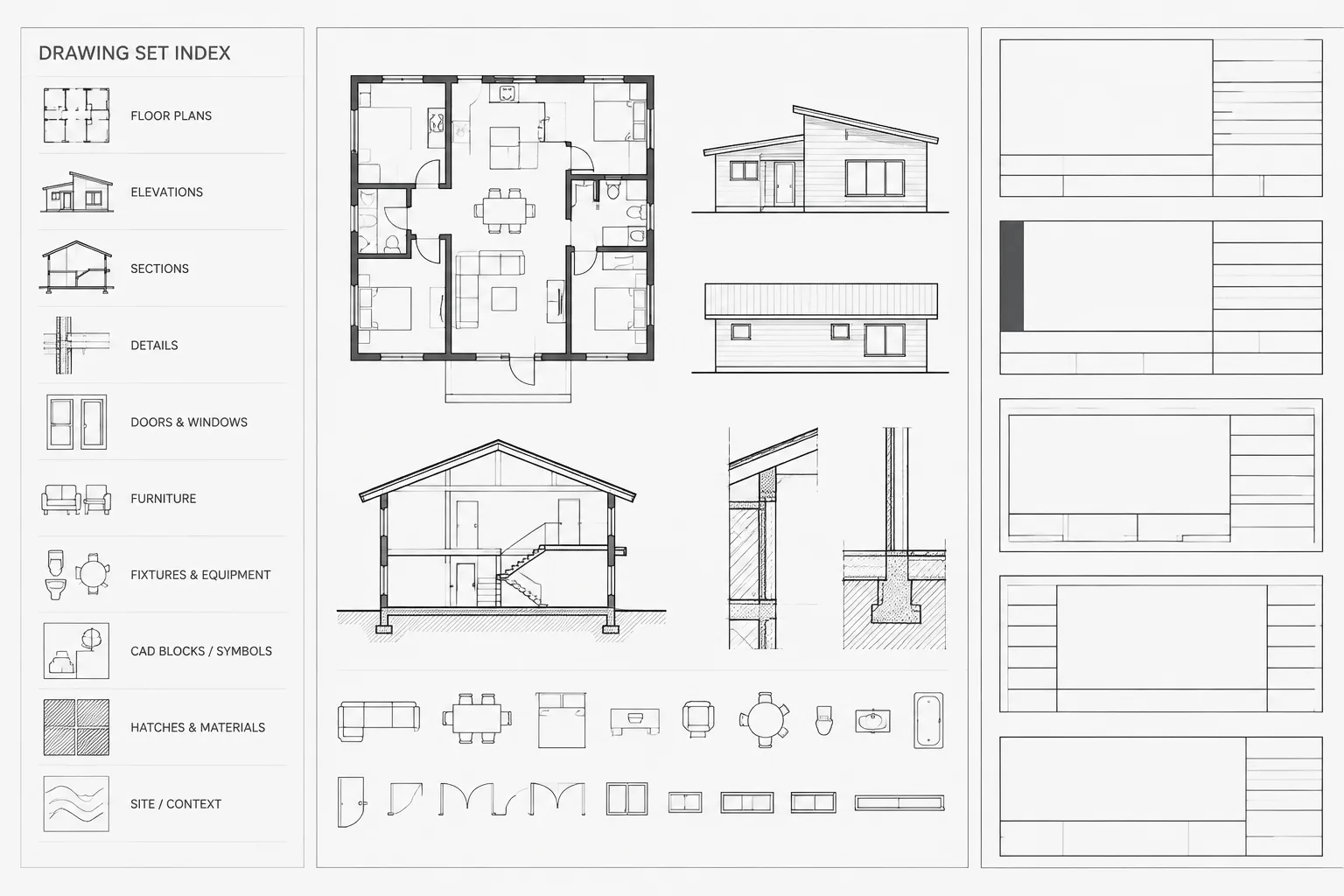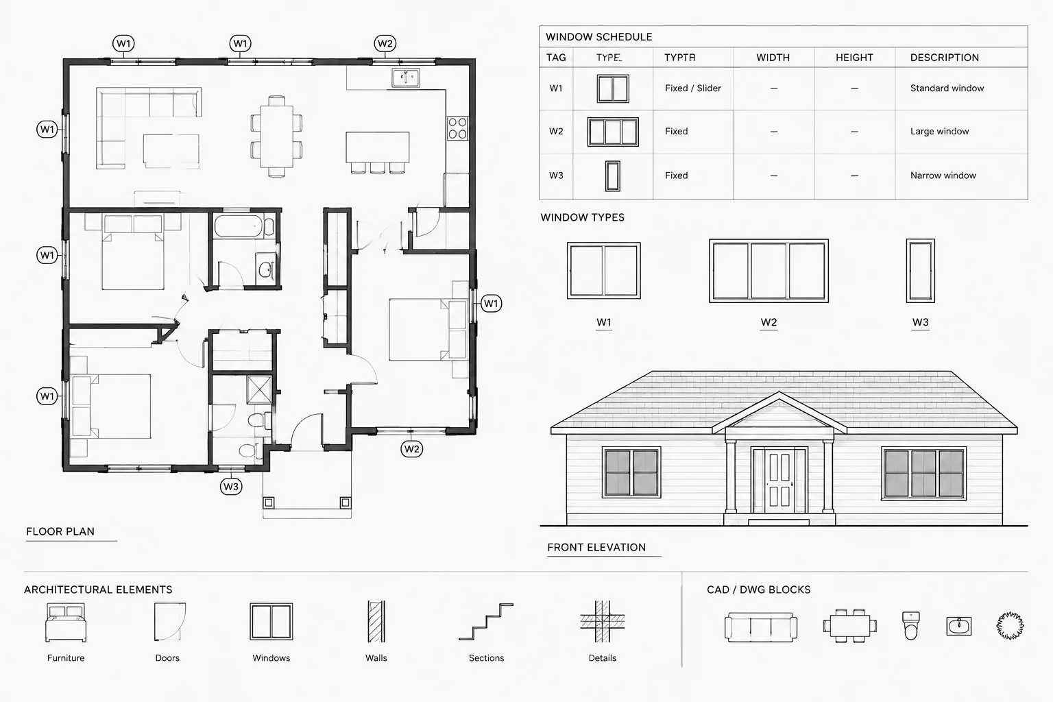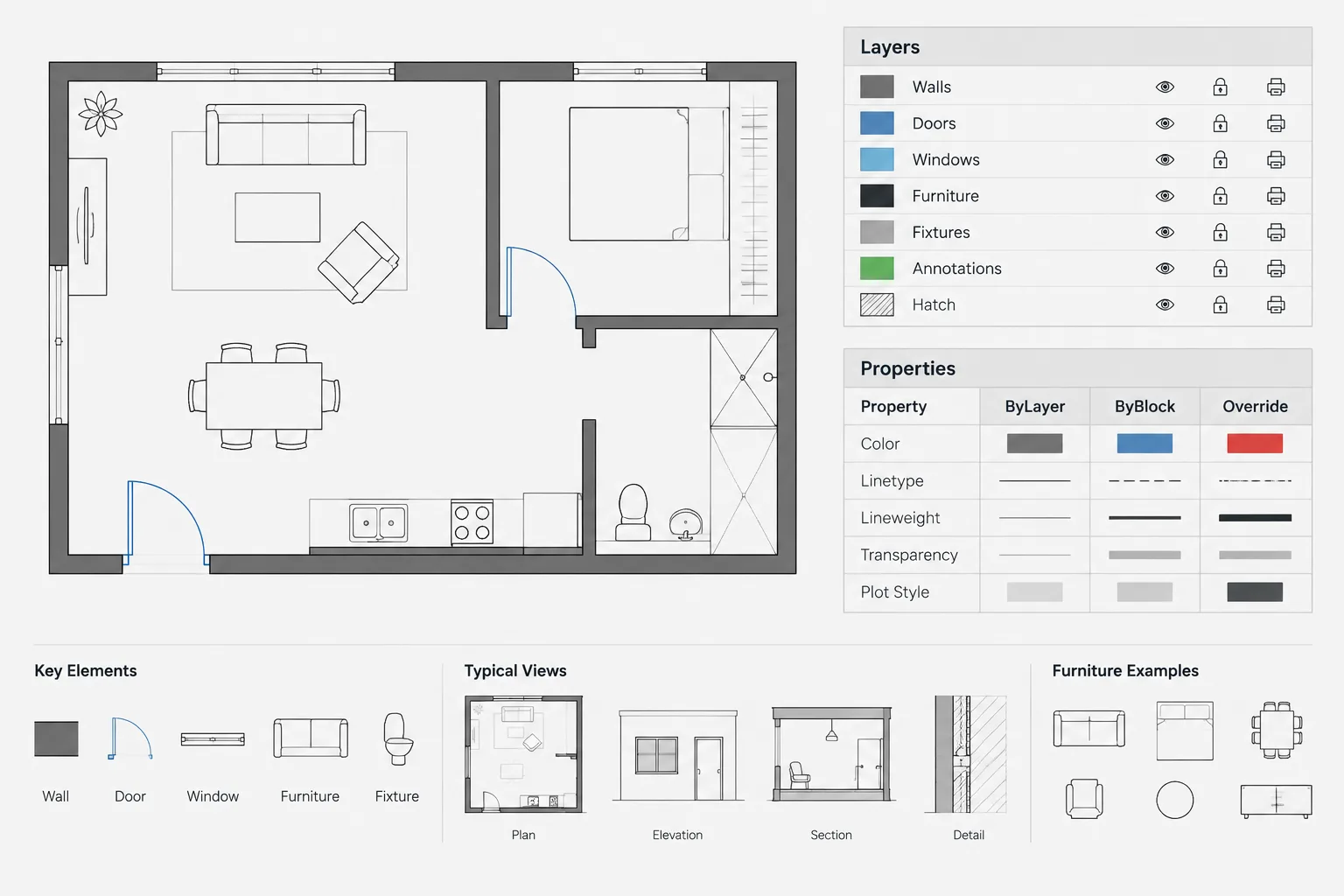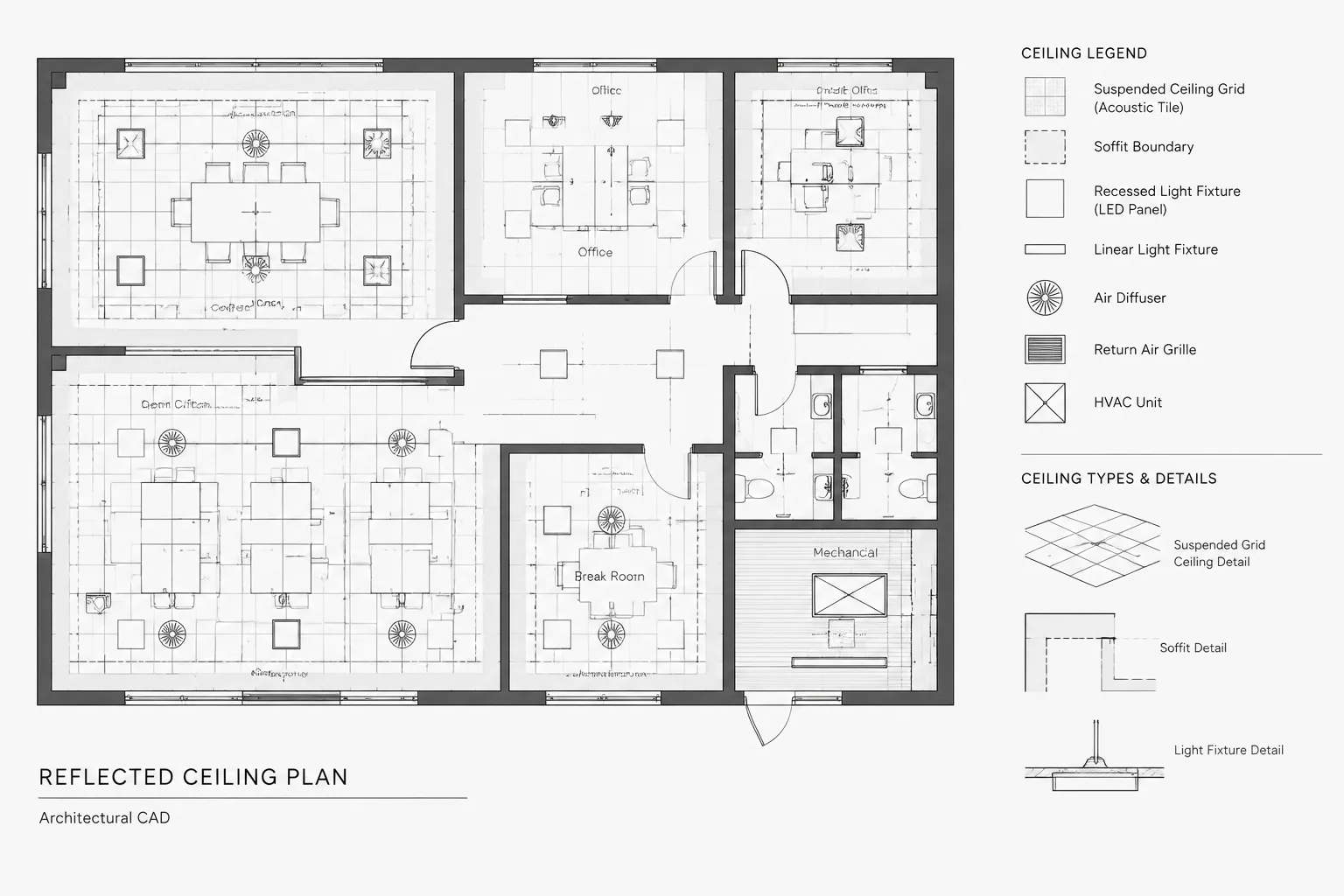
A suspended ceiling grid layout in CAD is both a drawing system and a coordination framework. Its repeated lines establish relationships among ceiling regions, perimeter conditions, light fixtures, air devices, access points, soffits, partitions, and adjoining spaces. Those relationships must remain understandable as architectural and consultant backgrounds change.
The workflow below focuses on reflected ceiling plan organization rather than product-specific installation detailing. It helps CAD users decide where a grid begins, where it stops, which alignments govern, and how to document unresolved conflicts without confusing architectural intent with consultant responsibility.
A suspended ceiling grid may look like a simple field of repeating lines, but a reliable reflected ceiling plan requires more than drawing a pattern across each room. The grid must respond to wall geometry, soffits, ceiling transitions, lighting, air devices, partitions, access panels, and other overhead elements. It must also remain legible when plotted and practical to revise as the design develops.
This workflow explains how to create a suspended ceiling grid layout in CAD without treating it as decorative hatching. The goal is to produce coordinated design intent that can be reviewed across architectural and consultant drawings. Actual grid components, module sizes, support conditions, perimeter details, and installation tolerances must be verified against the project requirements and selected ceiling system.
Start with the correct reflected ceiling plan background
Begin with a current architectural background rather than copying geometry from an outdated floor plan. The ceiling drawing should reference or derive from coordinated walls, columns, shafts, openings, and fixed casework that affects the overhead layout.
Before drawing the grid, confirm which elements define the visible ceiling boundary. A partition shown on the floor plan may stop below the ceiling, while a soffit or ceiling-height change may create a boundary that is not obvious in plan. Use the ceiling design, sections, and interior elevations to resolve these conditions.
- Verify room boundaries and partition locations.
- Identify soffits, bulkheads, ceiling pockets, and open-to-structure areas.
- Locate ceiling transitions and changes in material or elevation.
- Confirm which consultant backgrounds are current.
- Separate existing construction from new ceiling work where applicable.
Define ceiling regions before drawing modules
Divide the plan into logical ceiling regions. A region is an area that shares a ceiling type, elevation, orientation, and grid origin. One room may contain several regions when a central ceiling field is surrounded by a perimeter soffit, or when a corridor crosses an open office area with a different grid direction.
Defining regions first prevents a common drafting error: extending one continuous grid through walls, transitions, and unrelated spaces. Even where adjacent rooms use the same ceiling system, their layouts may require different starting points because of room geometry or design alignment.
Choose a meaningful grid origin
The grid origin controls where the repeating module begins. Select it intentionally rather than placing the first line at an arbitrary coordinate. Useful references can include a room centerline, a corridor axis, a major partition, a structural bay, a prominent opening, or an architectural feature.
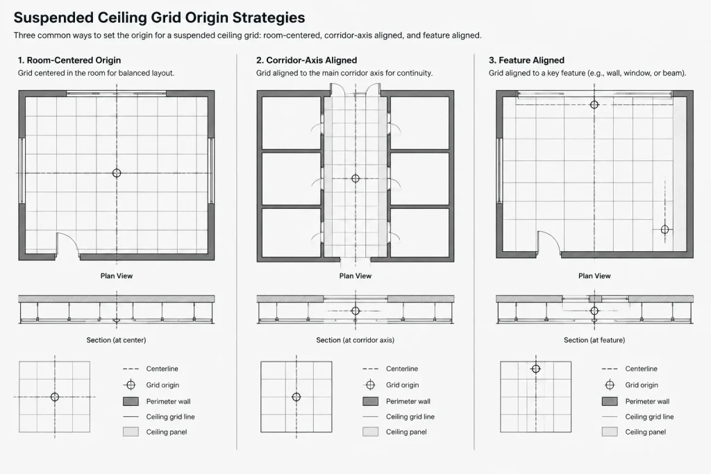
Record the logic behind the origin when it is not visually obvious. A construction note or clear dimension may be more useful than leaving installers to infer whether the grid is centered, aligned with a wall, or coordinated with another element. Do not assume that geometric centering is always the design goal; some spaces prioritize alignment with lighting, circulation, casework, or adjoining ceiling fields.
Build the grid as editable CAD geometry
Draw ceiling grids with geometry that can be revised efficiently. Lines or polylines copied in a controlled pattern are generally easier to edit than an exploded collection of unrelated segments. Arrays can be useful during layout, but the final organization should suit the office workflow and expected revisions.
Trim or clip the grid to the actual ceiling boundary. Avoid leaving grid lines hidden beneath walls or soffits simply because they do not plot. Excess geometry makes selection difficult, creates misleading intersections, and can reappear when backgrounds change.
For irregular rooms, establish the main field first and then resolve recesses, angled walls, and small offsets. This preserves the overall alignment instead of allowing minor perimeter geometry to control the entire layout.
Use blocks for repeated ceiling components
Use consistent blocks for lights, diffusers, return devices, access panels, speakers, detectors, and other repeated symbols when those elements are part of the architectural coordination background. Give each block a logical insertion point, such as its geometric center or a defined mounting reference.
Do not convert consultant symbols into architectural design commitments without review. The architectural reflected ceiling plan should communicate coordinated intent while preserving clear responsibility for engineering selection, performance, and final device requirements.
Evaluate perimeter conditions instead of forcing equal borders
Balanced borders can improve appearance, but equal-looking edge pieces are not automatically the correct solution. Room shape, ceiling openings, fixture groups, corridor continuity, and feature alignments may justify an offset layout.
Review perimeter conditions on all sides of each region. Very narrow fragments may be difficult to read and may signal that the grid origin needs adjustment. However, moving the entire grid to correct one edge can create worse conditions elsewhere. Compare the complete room rather than evaluating a single wall in isolation.
| Condition | CAD review | Coordination question |
|---|---|---|
| Rectangular room | Compare opposite perimeter fields | Is centering intended, or does another alignment govern? |
| Corridor | Check continuity through intersections and doors | Should the grid follow the corridor axis or align with adjacent rooms? |
| Irregular perimeter | Protect the primary grid field from minor offsets | Which wall or feature establishes the dominant direction? |
| Soffit edge | Stop the grid cleanly at the ceiling transition | Does the transition align with fixtures or partitions below? |
| Multiple connected rooms | Compare origins before extending the pattern | Is continuity important, or should each room be laid out independently? |
Coordinate fixtures and devices with the grid
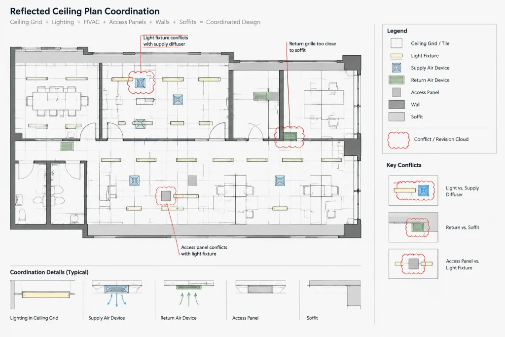
Once the basic grid is established, overlay the current lighting and mechanical backgrounds. Review each ceiling device in relation to modules, support lines, walls, and neighboring devices. A symbol that appears centered in a room may still conflict with the grid or with another discipline’s component.
Check these relationships systematically:
- Light fixtures relative to grid modules and architectural centerlines.
- Supply and return air devices relative to lights and ceiling boundaries.
- Access panels relative to equipment requiring service access.
- Speakers, sensors, and other devices relative to the intended visual pattern.
- Full-height partitions and rated assemblies that may affect ceiling continuity.
- Ceiling-mounted items near doors, tall casework, operable partitions, or overhead equipment.
Use a coordination markup or issue list for unresolved conflicts. Moving an architectural symbol without notifying the responsible consultant can create differences between drawing sets. Where consultant files are externally referenced, retain their original geometry and document requested changes separately.
Organize ceiling information with clear layers
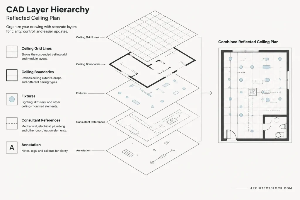
Place the grid, ceiling boundaries, fixtures, devices, annotations, and consultant references on distinct layers appropriate to the project template. This allows the drafter to isolate the grid for editing, reduce consultant backgrounds during plotting, and create different reflected ceiling plan views without duplicating geometry.
A practical organization separates at least the following information:
- Ceiling grid lines.
- Ceiling boundaries and transitions.
- Overhead features such as soffits and ceiling pockets.
- Architectural lighting or fixture symbols.
- Mechanical and electrical reference information.
- Ceiling tags, elevation markers, notes, and dimensions.
Layer names and plot properties should follow the established project standard. Avoid importing a downloaded ceiling pattern or consultant layer structure directly into the production file without review.
Annotate the layout without obscuring it
The grid should remain readable behind tags and notes. Place ceiling type tags in open areas and use leaders only when the tagged region could be misunderstood. Show ceiling elevations where changes occur, but coordinate them with the project’s level and datum conventions.
Dimension only the information needed to establish design intent. Useful dimensions may locate a grid origin, ceiling transition, soffit edge, or significant fixture alignment. Repetitive dimensions across every module usually add clutter without improving coordination.
If a ceiling region cannot be explained clearly in the overall reflected ceiling plan, create an enlarged view or a dedicated detail. Complex intersections often need sections or interior elevations to explain vertical relationships that a plan cannot show.
Run a focused quality-control review
Review the suspended ceiling grid at both model scale and intended sheet scale. A technically accurate layout may still fail if lineweights merge, symbols cover intersections, or referenced backgrounds plot too strongly.
- Confirm that each ceiling region has an intentional origin and direction.
- Check that grids stop at actual boundaries and transitions.
- Look for narrow or accidental perimeter fragments.
- Verify that ceiling symbols do not overlap walls, soffits, or one another.
- Compare architectural and consultant backgrounds for shifted devices.
- Check ceiling tags and elevations against sections and interior elevations.
- Inspect corridors and connected spaces for unexplained grid breaks.
- Plot a test sheet to review hierarchy, lineweight, and annotation density.
Treat the grid as coordinated design information
A well-drafted suspended ceiling grid is not merely a repeated pattern. It records how the ceiling relates to room geometry, fixtures, devices, transitions, and adjoining spaces. By defining regions, selecting deliberate origins, using editable geometry, and reviewing consultant overlays, CAD users can create reflected ceiling plans that are easier to understand and revise.
Before issuing the drawing, verify the layout against the selected ceiling system, project specifications, consultant requirements, and applicable project criteria. The CAD drawing communicates intent, but it does not replace product-specific detailing or professional review.
Manage ceiling-grid decisions through design changes
Ceiling coordination should continue after the first layout is drawn. A shifted partition, revised soffit, relocated fixture, or updated consultant reference can change the logic of an entire ceiling region. Review the governing origin and boundary before correcting individual grid lines or symbols.
Distinguish governing geometry from dependent geometry
Governing geometry establishes the layout. It may include a room axis, primary wall, ceiling transition, corridor alignment, or another deliberate architectural reference. Dependent geometry includes repeated grid lines and ceiling-mounted symbols positioned in response to that reference. Keeping this distinction clear makes revisions more controlled.
- When a boundary changes: confirm whether the original grid origin still produces the intended perimeter condition.
- When a device moves: determine whether the device should follow the grid or whether the ceiling layout requires broader review.
- When a consultant reference updates: compare revisions before replacing or repositioning architectural coordination symbols.
- When connected spaces change: review continuity across openings, corridors, and ceiling transitions rather than editing each room in isolation.
Prepare the reflected ceiling plan for handoff
Before sharing or issuing the CAD file, remove abandoned layout studies from production layers, confirm that references are current, and make unresolved coordination items easy to identify. The drawing should show the selected design direction without concealing open questions.
Where vertical conditions control the ceiling, coordinate the plan with sections, interior elevations, and ceiling details. A plan can locate a boundary or device, but it may not adequately explain the relationship among structure, soffits, partitions, suspension components, and service access.
Use a repeatable revision check
- Identify the ceiling region affected by the change.
- Confirm its boundary, direction, and governing origin.
- Review perimeter conditions around the complete region.
- Compare architectural symbols with current consultant information.
- Check related tags, notes, dimensions, sections, and elevations.
- Review the result at the intended plotted presentation.
This sequence helps prevent local edits from breaking the larger reflected ceiling plan. Final construction information must still be checked against the selected system, project documentation, consultant requirements, and professional review.
Frequently asked questions
Should a suspended ceiling grid always be centered in the room?
No. Centering may create a balanced appearance, but another relationship may govern the design. The grid might instead align with a corridor, fixture group, partition, opening, structural reference, casework, or adjoining ceiling field. The important step is to make the selected origin deliberate and document it clearly.
Why should the grid be divided into separate ceiling regions?
Separate regions allow each ceiling area to have its own boundary, direction, elevation, type, and origin. This prevents a repeating pattern from incorrectly passing through walls, soffits, transitions, or unrelated rooms.
Should consultant ceiling symbols be edited in the architectural file?
Consultant reference geometry should generally remain distinguishable from architectural coordination information. Requested relocations can be documented through markups or an issue list so differences between drawing sets are visible and can be reviewed by the responsible parties.
How should an irregular room be approached?
Establish the dominant ceiling field from the primary room geometry or design reference, then resolve recesses, angled walls, and minor offsets at the perimeter. Allowing every small offset to control the grid can weaken the overall alignment.
When is an enlarged ceiling view useful?
An enlarged view is helpful when tags, dimensions, fixtures, devices, and transitions cannot be shown clearly in the overall reflected ceiling plan. Sections or interior elevations may also be needed when the key issue is vertical rather than planar.
What should be checked after a partition or soffit moves?
Recheck the ceiling-region boundary, grid origin, perimeter conditions, nearby devices, annotations, and related views. Avoid trimming only the visible lines without confirming whether the layout logic remains valid.