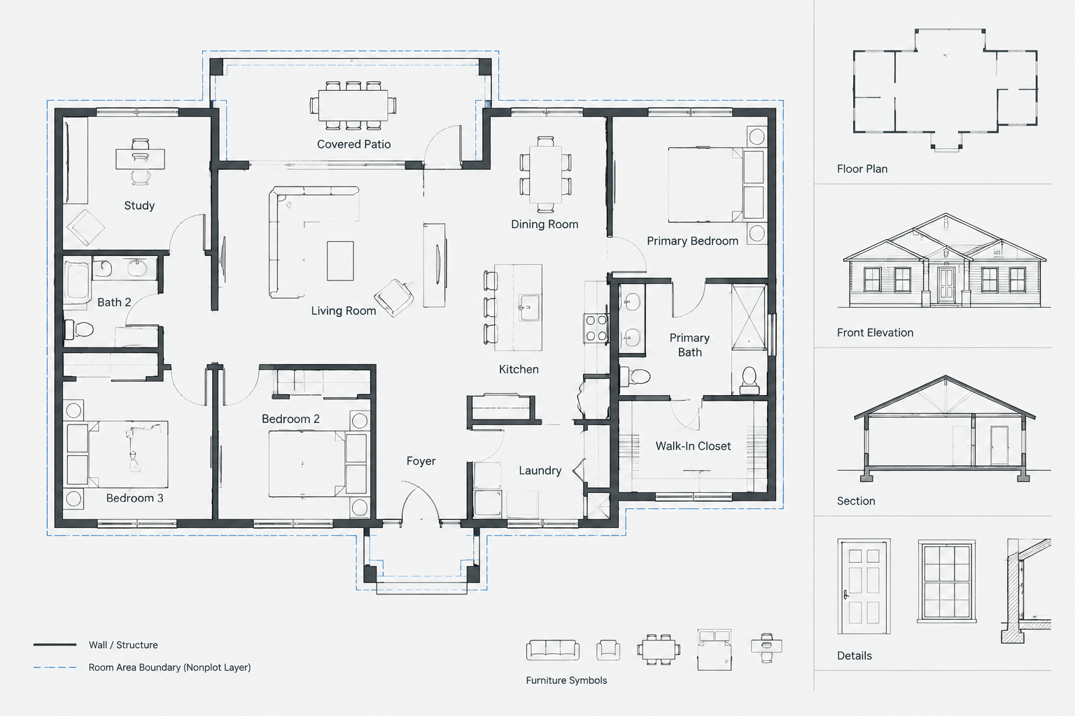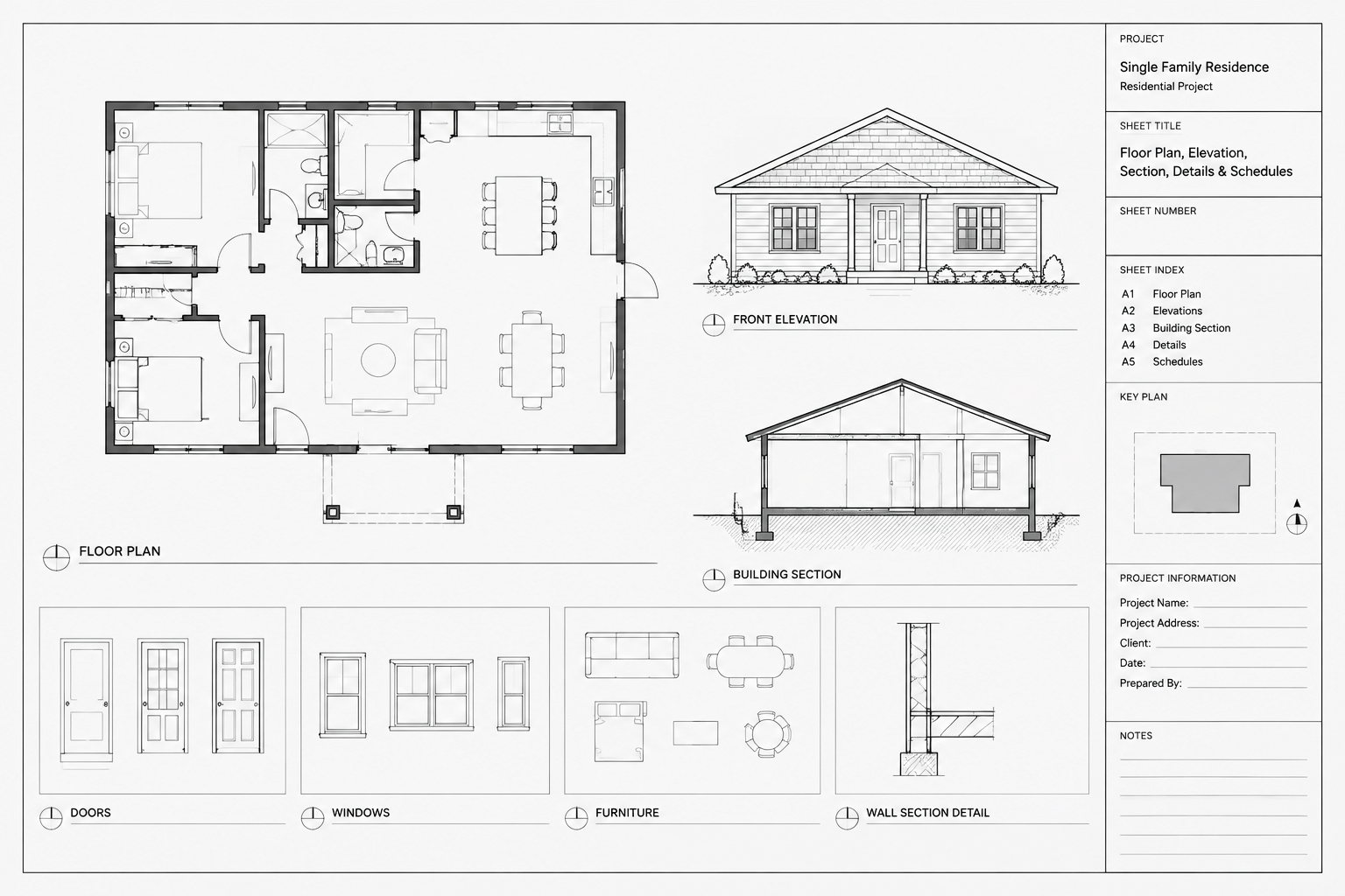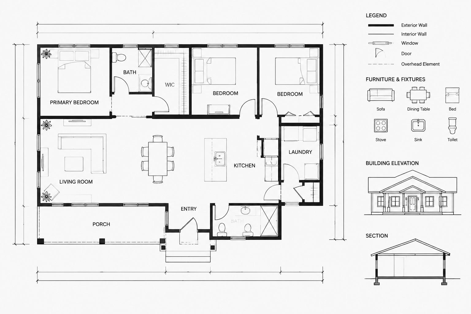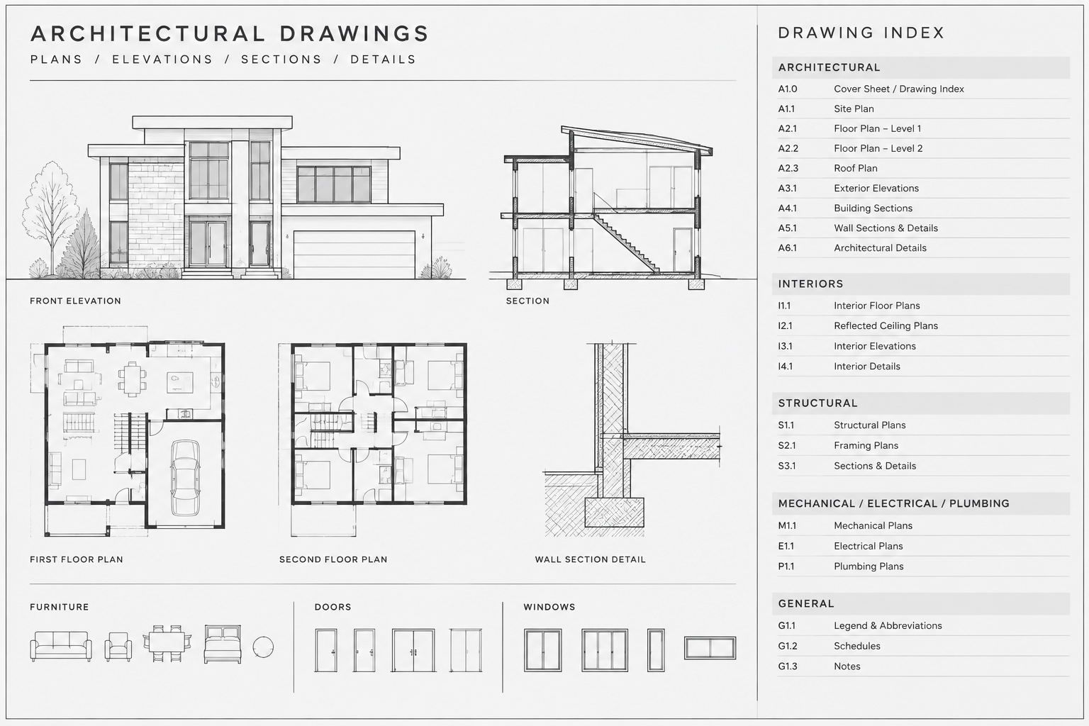
Architectural grid lines provide a shared reference system for locating major building elements across a drawing set. They help designers, consultants, builders, and reviewers relate positions shown in plans to corresponding elevations, sections, and details. A well-organized grid can make a complex project easier to navigate, while an inconsistent grid can create ambiguity even when the underlying geometry is accurate.
Grid drafting is not simply a matter of drawing centerlines through columns. The grid must be established deliberately, labeled consistently, coordinated between files, and presented clearly at each sheet scale. The following workflow explains how to create and manage architectural grid lines in CAD without treating them as isolated annotation.
What an Architectural Grid Represents
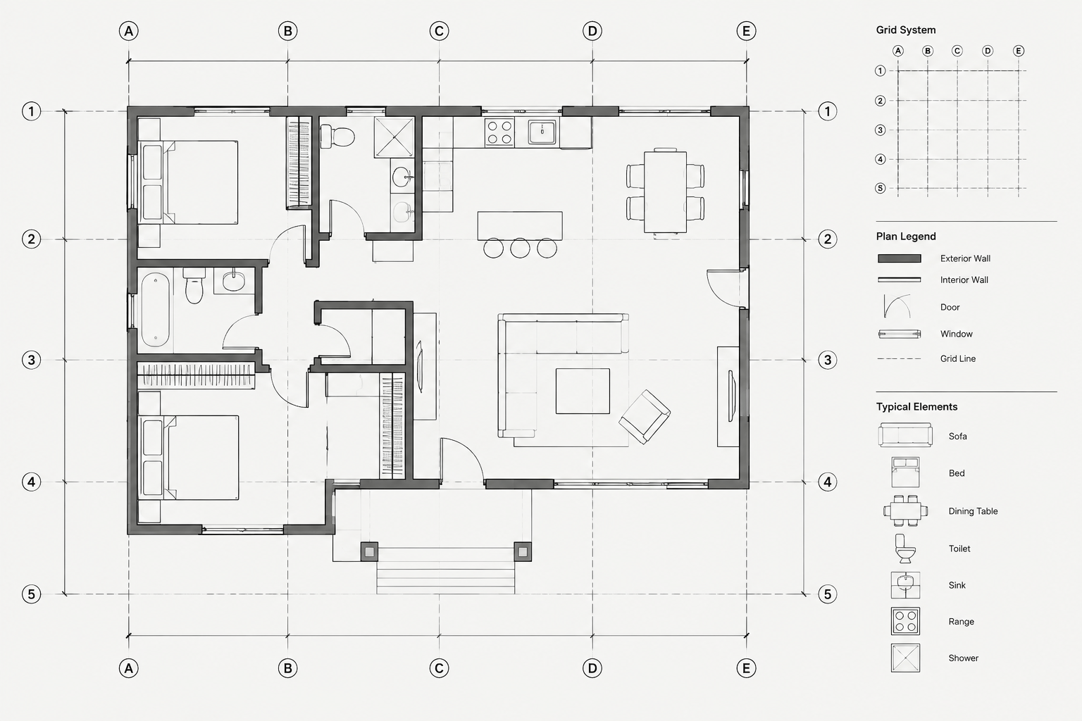
A grid is a set of identifiable reference axes used to describe location. In a regular building, one grid direction may run along the building length while the other runs across it. Each axis receives a unique identifier, allowing a point or element to be located by the intersection of two references.
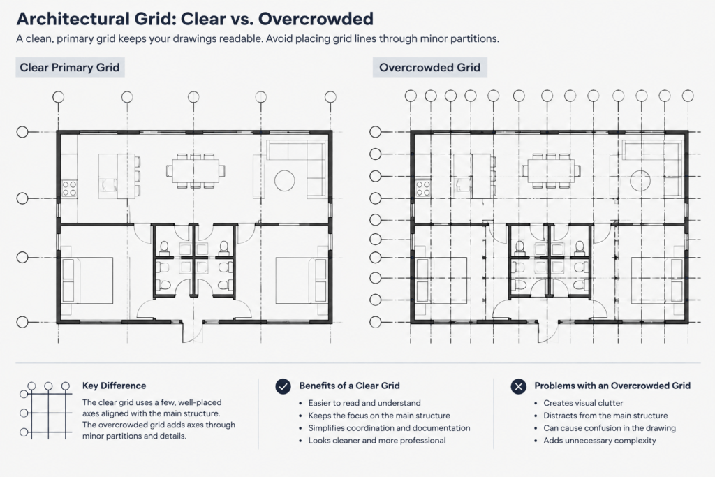
Grids commonly align with structural framing, column centerlines, major wall systems, planning modules, or other stable project geometry. However, a grid should not be added for every partition or minor alignment. Too many axes weaken the hierarchy and make references harder to communicate.
The project team should determine what the grid controls. An architectural drafter should not assume that a wall face, column edge, or component centerline is the correct basis without checking the design and consultant information.
Establish the Grid Before Developing Detailed Plans
Set up the primary grid early enough that it can guide the base drawing. Moving a grid after plans, dimensions, sections, and consultant backgrounds have been developed can produce widespread coordination problems.
Before drawing the axes, review:
- The intended building orientation and major organizing geometry
- Available structural or consultant backgrounds
- Column, bearing-wall, core, and facade alignments
- Changes in direction, offsets, or separate building wings
- Existing conditions that may not follow a regular pattern
- The project origin and coordinate strategy
Grid spacing should come from verified project geometry rather than a generic template. When imported or downloaded plans are used as a starting point, confirm their scale, units, rotation, and alignment before adopting any grid positions.
Create the Primary Axes in Model Space
Draw grids as full-scale model-space objects. Keep them independent from walls, columns, and other building geometry so their display can be controlled without affecting the design.
A practical setup normally includes a dedicated grid layer with an assigned linetype, color, and plotted lineweight. The exact layer name should follow the office or project CAD standard. Avoid placing grids on a general annotation layer if that makes them difficult to isolate, lock, or coordinate.
Use a Stable Geometric Basis
Choose a verified base axis and build the remaining grid from known project relationships. CAD offset and copy tools can help preserve parallel alignment, but the resulting locations still need to be checked against the design.
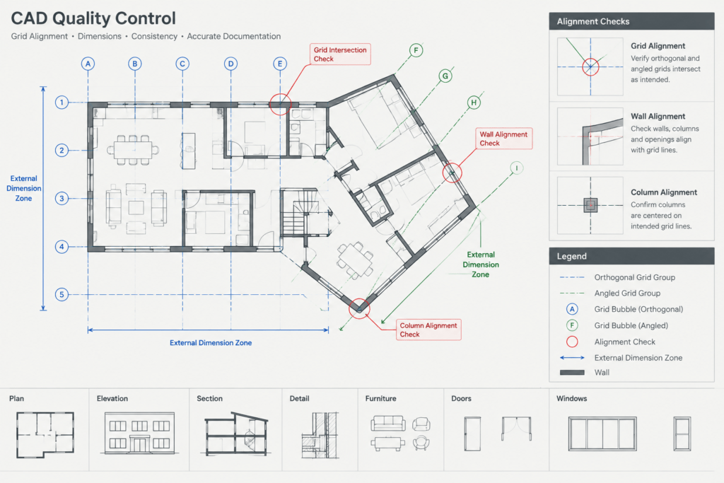
For orthogonal buildings, confirm that the two main grid directions are perpendicular when that is the design intent. For angled, radial, or segmented buildings, define the center, rotation point, or controlling geometry before expanding the grid system. Do not correct a visibly irregular existing building into a perfect grid unless the project documentation clearly establishes that intent.
Keep Grid Lines Continuous and Predictable
A primary grid axis should remain geometrically continuous even when portions are not displayed on a particular sheet. Avoid drawing several unrelated line segments that only appear to be one axis. Continuous source geometry is easier to coordinate, extend, and verify.
Where a plan contains separate wings or a significant change in orientation, it may be clearer to use distinct grid groups. Their naming must remain unambiguous across the complete drawing set.
Develop a Clear Grid Labeling System
Grid identifiers should be unique, legible, and arranged in an understandable sequence. One direction is often identified with letters and the other with numbers, but the project team may adopt a different convention. The important requirement is that the same identifier always refers to the same axis.
Some characters can be confused with numbers or with one another, particularly at small plotted sizes. Review the chosen sequence visually rather than relying only on automatic ordering.
When an additional axis is inserted between established grids, use a supplementary identifier that preserves the surrounding sequence. Renaming every later grid can break existing references in sections, details, consultant files, and field communication.
Build Consistent Grid Bubbles
Create grid heads as reusable CAD blocks rather than redrawing the circle or other enclosure each time. A well-built block keeps the text position, enclosure, and line connection consistent. If editable identifiers are required, the block can use an attribute or another office-approved text method.
Check that the bubble remains readable at the intended plotted scale. The model-space representation may need to vary by drawing type or annotation workflow, but its printed appearance should stay consistent with the rest of the set.
Coordinate Grids Across Plans, Elevations, and Sections
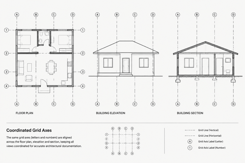
A grid becomes useful only when it is carried through related views. Plan axes should correspond to the same building locations shown in elevations and sections. Copying grid graphics by eye into each drawing is risky because later revisions may not be transferred consistently.
Where the project uses external references, keep the controlling grid in an appropriate shared base file or another coordinated source defined by the CAD management plan. Referenced grids should not be casually moved in individual sheet files. If a sheet needs different visibility or graphic treatment, manage the display rather than creating a competing grid system.
| Drawing type | Grid purpose | Coordination check |
|---|---|---|
| Floor plan | Locates major elements in two directions | Verify intersections against the coordinated base plan |
| Elevation | Relates facade elements to plan locations | Confirm each vertical axis matches the plan position |
| Building section | Connects cut geometry to the project reference system | Check grids against columns, walls, and section extents |
| Enlarged plan | Maintains orientation within a partial building view | Show only relevant axes while retaining original labels |
| Consultant background | Provides a common location reference | Compare origin, rotation, identifiers, and revision status |
Dimension the Grid Instead of Repeating Every Element
Grid dimensions communicate the spacing between controlling axes. They can reduce the need to dimension the same major relationship repeatedly to individual columns or walls. This does not eliminate element-specific dimensions where those are needed; it creates a stable dimensional framework.
Arrange grid dimensions outside the main plan geometry whenever practical. A clear hierarchy may include individual spacing between axes and a broader overall relationship. Avoid dimension strings that cross room labels, door swings, keynotes, or other essential information.
Dimensions must agree with the actual axis geometry. Editing dimension text to display a preferred value without correcting the model creates a hidden discrepancy. If a dimension is unexpected, investigate the grid and project geometry rather than masking the issue.
Handle Irregular and Existing Buildings Carefully
Not every project fits a uniform rectangular grid. Renovations may contain skewed walls, undocumented shifts, additions from different periods, or incomplete survey information. In these cases, use only as much grid structure as the project can reliably support.
A primary grid can describe the main building while secondary references locate irregular portions. Offset, angled, or radial axes should be graphically distinct enough to understand, but they must remain part of one coordinated naming system.
Do not imply a level of surveyed accuracy that has not been verified. If grid positions depend on field measurements, consultant data, or existing documents, follow the project team’s method for recording and confirming those sources.
Common Grid Drafting Problems
- Duplicate identifiers: Two axes use the same label in different locations.
- Uncoordinated backgrounds: Architectural and consultant grids have different origins, rotations, or spacing.
- Broken axes: Separate line segments drift out of alignment after editing.
- Excessive grids: Minor walls and components receive unnecessary identifiers.
- Bubble conflicts: Grid heads overlap dimensions, view titles, crop boundaries, or other bubbles.
- Sheet-only corrections: A grid is moved in one drawing without updating the controlling model.
- Inconsistent labels: Plans, elevations, and sections refer to the same axis by different names.
- Unverified imported geometry: A grid is adopted from a DWG before its units and coordinates are checked.
Grid Quality-Control Checklist
Before issuing or sharing the drawing set, perform a dedicated grid review rather than treating grids as ordinary background graphics.
- Confirm that every identifier is unique and follows the agreed sequence.
- Check that the axes align with the intended controlling elements.
- Compare architectural grids with current consultant references.
- Verify that plan grids correspond to elevations and sections.
- Inspect bubble size, text position, and plotted legibility.
- Check grid dimensions against the actual model geometry.
- Remove obsolete axes and unexplained duplicate linework.
- Confirm that partial plans retain enough grids to establish location.
- Review layer, linetype, lineweight, and visibility settings.
- Record and communicate any grid revision that affects other files.
Treat the Grid as Shared Project Data
An architectural grid is both graphic information and a coordination tool. Its value comes from stability, consistency, and clear relationships to the building. By establishing a reliable source, using disciplined labels, coordinating related views, and checking each revision, CAD users can create drawing sets that are easier to navigate and less vulnerable to location errors.
The final grid should reflect verified project information and the team’s agreed drafting method. It should never be assumed to establish structural layout, construction tolerances, or field conditions without appropriate professional coordination.