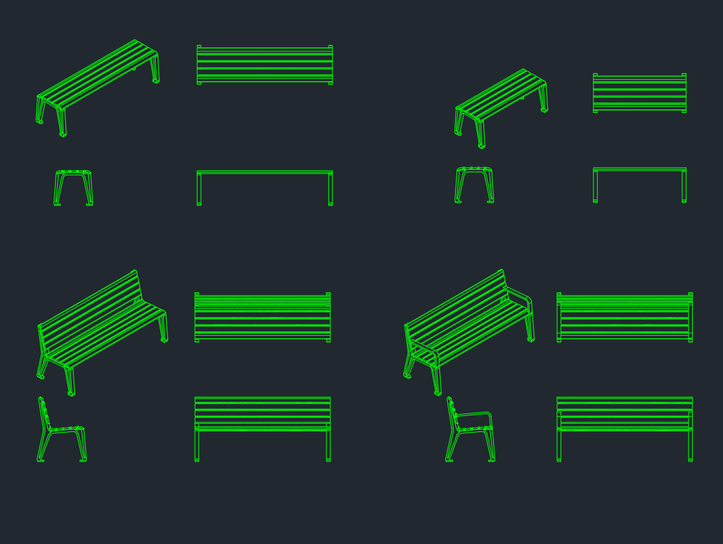
To organize architectural detail sheets in CAD effectively, treat each sheet as part of a coordinated information system rather than a collection of available drawings. Detail identity, source-file control, sheet placement, callout references, annotation, and revision status all need to remain connected as the drawing set develops.
The following workflow explains how to establish that structure, arrange related construction conditions, manage reusable details, and review the published sheet. It applies broadly to architectural drafting environments, but each project should also follow the responsible design professional’s documentation requirements and the office’s approved CAD standards.
Architectural detail sheets bring together enlarged drawings that explain assemblies, interfaces, and construction conditions that cannot be communicated clearly in plans, elevations, or building sections. A well-organized detail sheet helps readers locate information quickly and understand how each detail relates to the rest of the drawing set. A poorly organized sheet can contain technically correct drawings yet still create confusion through inconsistent titles, duplicate identifiers, unclear references, or unrelated details placed together.
Organizing architectural detail sheets in CAD is therefore more than arranging viewports on a layout. It requires a controlled system for classifying details, assigning references, managing source files, coordinating callouts, and distinguishing reusable information from project-specific design decisions.
Start with the purpose of the detail sheet
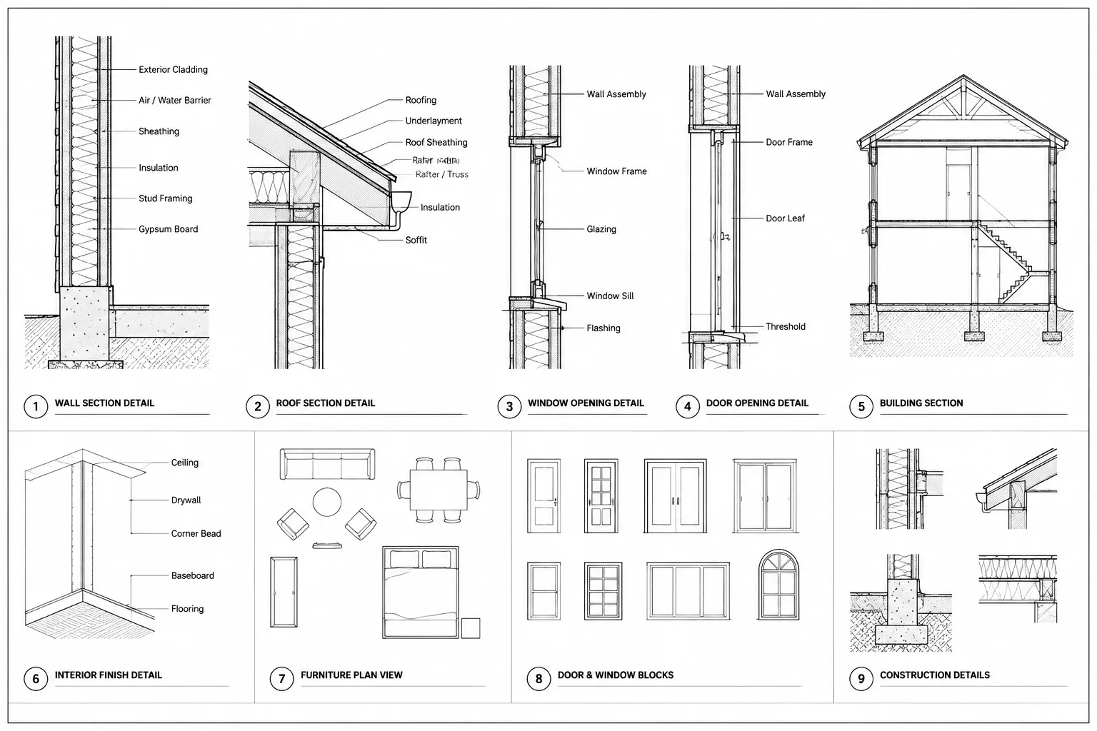
Before placing details, identify what the sheet is intended to communicate. Some sheets focus on a building system, while others collect details associated with a particular area or drawing discipline. Common organizational approaches include:
- Exterior wall and building-envelope details
- Roof edge, parapet, and roof transition details
- Door, window, and storefront interface details
- Interior partition and finish details
- Stair, railing, and guard details
- Millwork and casework details
- Floor, slab edge, and foundation interface details
- Typical accessibility-related mounting or clearance details, subject to project verification
A sheet should have a recognizable subject rather than becoming a holding area for unrelated drawings. When a project has only a few details in one category, combining categories may be reasonable, but the sheet title and internal arrangement should still make the content easy to scan.
Develop a consistent detail identification system
Every placed detail needs a unique identifier that works with its sheet reference. The same identifier should appear in the detail title, the originating callout, and any drawing index or coordination record that tracks the view.
Do not assign identifiers solely according to the detail’s temporary position during early drafting. Details frequently move as sheets develop. A controlled workflow separates the identity of the detail from the drafting team’s informal descriptions, then updates references whenever sheet placement changes.
Use descriptive working names
In addition to the published detail title, give each CAD source view a useful working name. A label such as “parapet at masonry wall” is easier to manage than a generic name such as “detail” or “section.” Descriptive names help when searching folders, reviewing xrefs, comparing similar conditions, and assembling later drawing issues.
Published titles should state the condition being shown. Avoid titles that are so broad that they could apply to several different details. Location qualifiers, assembly types, and interface descriptions can help distinguish related conditions without embedding unverified product or code claims.
Choose a reliable CAD source structure
Detail drawings can be stored in several ways. The right method depends on project size, team structure, and office standards, but the approach should remain consistent throughout the set.
| Source method | Useful application | Main coordination concern |
|---|---|---|
| Details drawn directly in a sheet file | Small projects or limited one-off details | Geometry can become difficult to reuse or review separately |
| Separate model files referenced into sheets | Larger sets and multi-user production | Paths, layers, clipping, and reference status must be controlled |
| Multiple related details in one model file | Details sharing common geometry or subject matter | Changes to shared content must not unintentionally affect other views |
| Copied details from an office library | Starting points for recurring assemblies | Every note, component, and condition must be verified for the current project |
Whichever structure is selected, avoid unexplained duplicate geometry. If several sheets contain independent copies of the same detail, later revisions may be applied to one copy and missed in another. When repetition is necessary, establish which file is the controlled source.
Arrange details for reading, not merely for filling space
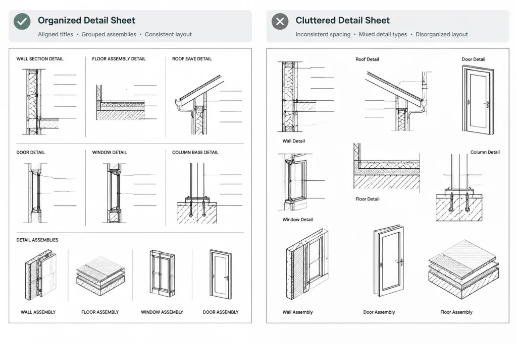
A detail sheet should have a visible hierarchy. Readers typically look for the detail identifier, title, drawing, dimensions, notes, and references in a predictable sequence. Aligning these elements across the sheet makes comparison easier and reduces visual noise.
Use a consistent title location and reserve enough white space around each drawing. Dense packing can make leaders, dimensions, and adjacent details appear connected when they are not. At the same time, excessive gaps may hide the relationship between details that describe the same assembly.
Group related conditions
Place related details near each other when practical. For example, a vertical assembly detail can be positioned near enlarged head, jamb, sill, base, or transition conditions associated with it. This arrangement allows readers to understand the larger assembly before examining individual interfaces.
Sequence can also follow the building logically, such as moving from lower conditions to upper conditions or from exterior interfaces to interior interfaces. The exact reading order is less important than applying a deliberate and repeatable structure.
Keep orientation intentional
Similar details should use consistent orientation where possible. Reversing or rotating a copied detail simply to fit an open area can make comparison more difficult. If orientation differs from the related plan or section, provide enough context to prevent misinterpretation.
Control scale and annotation carefully
Each detail should be drawn at full size in model space when that matches the office workflow, then displayed through a correctly scaled and locked viewport. Annotation may be model-based, paper-based, or managed through an annotative workflow, but the team should not mix methods casually within the same sheet.
The selected scale must provide enough room for legible dimensions, leaders, material indications, and component relationships. Enlarging a drawing does not automatically make it more informative. The amount of modeled or drafted information should suit the intended view.
Before issue, confirm that every published scale label matches the actual viewport or output. If a detail is intentionally not scaled, its title should communicate that condition according to the project’s drafting conventions. Users should not rely on measuring a printed detail to determine a construction requirement.
Coordinate detail callouts with source views
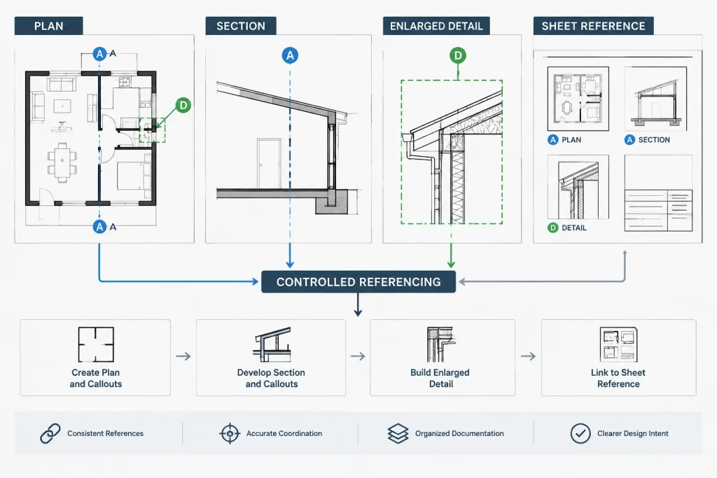
A detail is useful only when readers can find where it applies. Plan, elevation, section, and enlarged-view callouts should point to the correct detail and sheet. Conversely, the detail should contain enough context to show what condition the callout represents.
Use a callout register or another controlled review list when automatic referencing is not available. At minimum, track:
- The detail identifier and title
- The sheet on which the detail appears
- The drawings that reference it
- The source CAD file or model location
- Whether the detail is typical or location-specific
- The review status and latest coordinated revision
When a detail moves between sheets, search for every associated callout rather than updating only the most obvious plan reference. References may also appear in sections, elevations, schedules, general notes, or other details.
Distinguish typical details from project-specific details
Reusable details can improve efficiency, but they should be treated as starting information rather than automatically valid solutions. A library detail may contain assumptions about wall construction, structure, waterproofing, finishes, tolerances, or products that do not match the current project.
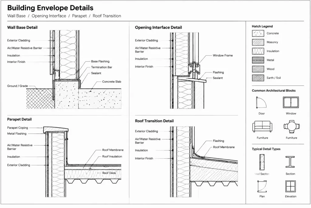
Marking a detail as typical should mean that the team has identified multiple applicable locations and verified the relevant conditions. It should not be used to avoid documenting meaningful differences. If adjacent locations vary, create separate details or clearly identify the limits of the typical condition.
Review imported details before placing them
- Remove obsolete project names, references, and revision marks.
- Check layers, lineweights, text styles, dimension styles, and units.
- Verify that material labels match the current assemblies.
- Confirm that referenced products or proprietary notes are appropriate.
- Review connections with structural and building-system information.
- Replace vague notes with coordinated project language where needed.
- Confirm that every shown condition exists in the current design.
Use layers and graphics to clarify assembly hierarchy
Detail layers should support both editing and plotted communication. Separate major element categories, annotations, dimensions, hatches, overhead or concealed items, and reference geometry according to the project layer system. Avoid placing an entire imported detail on a single layer unless it is being retained only as a temporary reference.
Lineweight should distinguish cut elements, visible edges, secondary components, and background information. Hatches should clarify materials or assemblies without overpowering notes and dimensions. If a hatch becomes visually dense or causes unstable output, simplify it while preserving the intended material distinction.
Run a sheet-level quality-control review
Review details individually and as a complete sheet. A drawing may be correct in isolation but inconsistent with neighboring details or the larger set.
- Confirm that every identifier is unique on the sheet.
- Match each title and reference to the intended condition.
- Check viewport scale, lock status, clipping, and layer visibility.
- Look for duplicate notes, conflicting dimensions, and overlapping leaders.
- Compare repeated materials and assemblies across related details.
- Verify that section cuts and continuation references lead somewhere valid.
- Check that revision changes were applied to every affected view.
- Plot or publish the sheet and review the final output rather than relying only on model-space display.
A final visual scan should also check balance and readability. Crowded regions, isolated titles, inconsistent spacing, and abrupt changes in annotation size often reveal coordination problems that command-based checks will not find.
Maintain the sheet as the project changes
Detail organization is not a one-time setup task. Design development, consultant input, substitutions, and field clarification can change which details are required and where they apply. Remove superseded views deliberately, update all references, and retain revision records according to the project’s document-control process.
The strongest architectural detail sheets function as coordinated navigation tools as well as technical drawings. Clear grouping, stable identifiers, controlled sources, readable graphics, and verified callouts make the information easier to use and reduce the chance that an outdated or unrelated detail will be mistaken for the intended condition.
A practical decision sequence for detail-sheet planning
Begin with a list of conditions that require enlarged documentation. For each condition, identify where it originates, what other views refer to it, whether it shares an assembly with another detail, and whether an existing office detail is being used as a reference. This creates a coordination record before sheet composition begins.
Next, sort the details by subject and drawing relationship. Closely related interfaces can be placed in a common visual group, while unrelated assemblies should remain separated even when combining them would fill empty sheet space. Establish descriptive working names and stable identities before assigning final sheet locations.
After placement, coordinate viewport behavior, annotation, titles, and callouts as a connected task. A change to sheet location may affect references elsewhere in the set, while a scale or clipping change may alter the clarity of notes and dimensions. Review those dependencies together rather than treating layout as a final cosmetic step.
Use status information to prevent premature publication
Drafting teams benefit from distinguishing details that are being developed, details awaiting coordination, details approved for placement, and details superseded by later work. The exact status terminology should follow the project’s document-control process, but its meaning should be clear to everyone editing the files.
Temporary graphics, unresolved notes, and copied library content should not look indistinguishable from reviewed project information. Keep working content visibly controlled and remove it from the published view when it is not intended for issue.
Check relationships, not only individual drawings
Many detail-sheet errors occur between views rather than within a single detail. Compare related head, jamb, sill, base, edge, and transition conditions to confirm that materials, terminology, orientation, and continuation logic agree. Also compare details with the plans, elevations, sections, schedules, and consultant information that establish the surrounding condition.
When conflicts appear, determine which drawing is the controlled source before editing repeated information. Correcting isolated copies without resolving the source can leave the set internally inconsistent.
Review the published artifact
CAD display alone does not reveal every sheet problem. Review the actual plotted or published output for lineweight hierarchy, hatch density, clipped annotation, title alignment, reference clarity, and unintended layer visibility. The final sheet should make both the subject of each detail and its relationship to the project easy to understand.
Frequently asked questions
Should architectural details be organized by building area or assembly type?
Either approach can work. Assembly-based grouping is useful when readers need to compare related interfaces, while area-based grouping can help when a distinct project location contains several coordinated conditions. Choose the method that makes application clear, then use it consistently across related sheets.
Should detail identifiers change when drawings move?
The team’s identification method should remain controlled when details are relocated. If sheet placement forms part of the published reference, every callout, title, index entry, and coordination record affected by the move must be updated and checked.
Is it acceptable to copy a detail from an office library?
A library detail can be a drafting starting point, but it must be reviewed against the current design. Notes, materials, interfaces, references, products, layers, and graphic conventions may carry assumptions that do not apply to the project.
Why should related details use a consistent orientation?
Consistent orientation helps readers compare components and trace assembly continuity. Rotation or mirroring solely to occupy open sheet space can obscure relationships and increase the risk of misreading a condition.
How should a team handle repeated details?
Identify a controlled source whenever the same information appears in more than one location. If independent copies are unavoidable, include them in revision review so that a change is not applied to one copy while the others remain outdated.
What should be checked after a detail sheet is rearranged?
Review identifiers, titles, callouts, indexes, viewport settings, clipping, layer visibility, continuation references, and revision information. Then inspect the published output to confirm that the revised arrangement remains legible and easy to navigate.