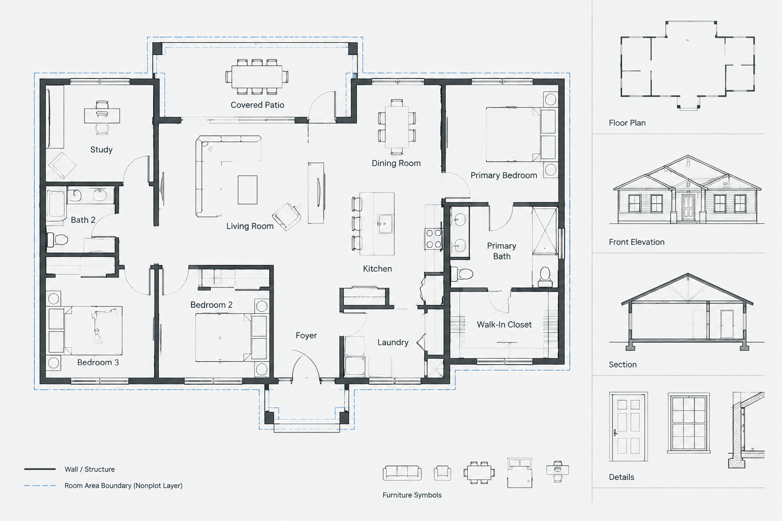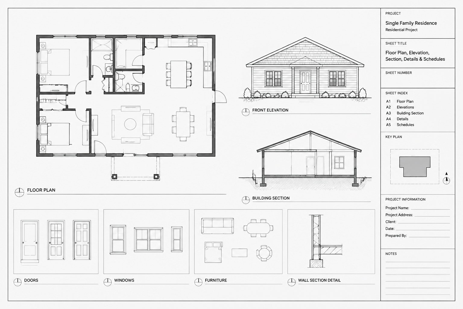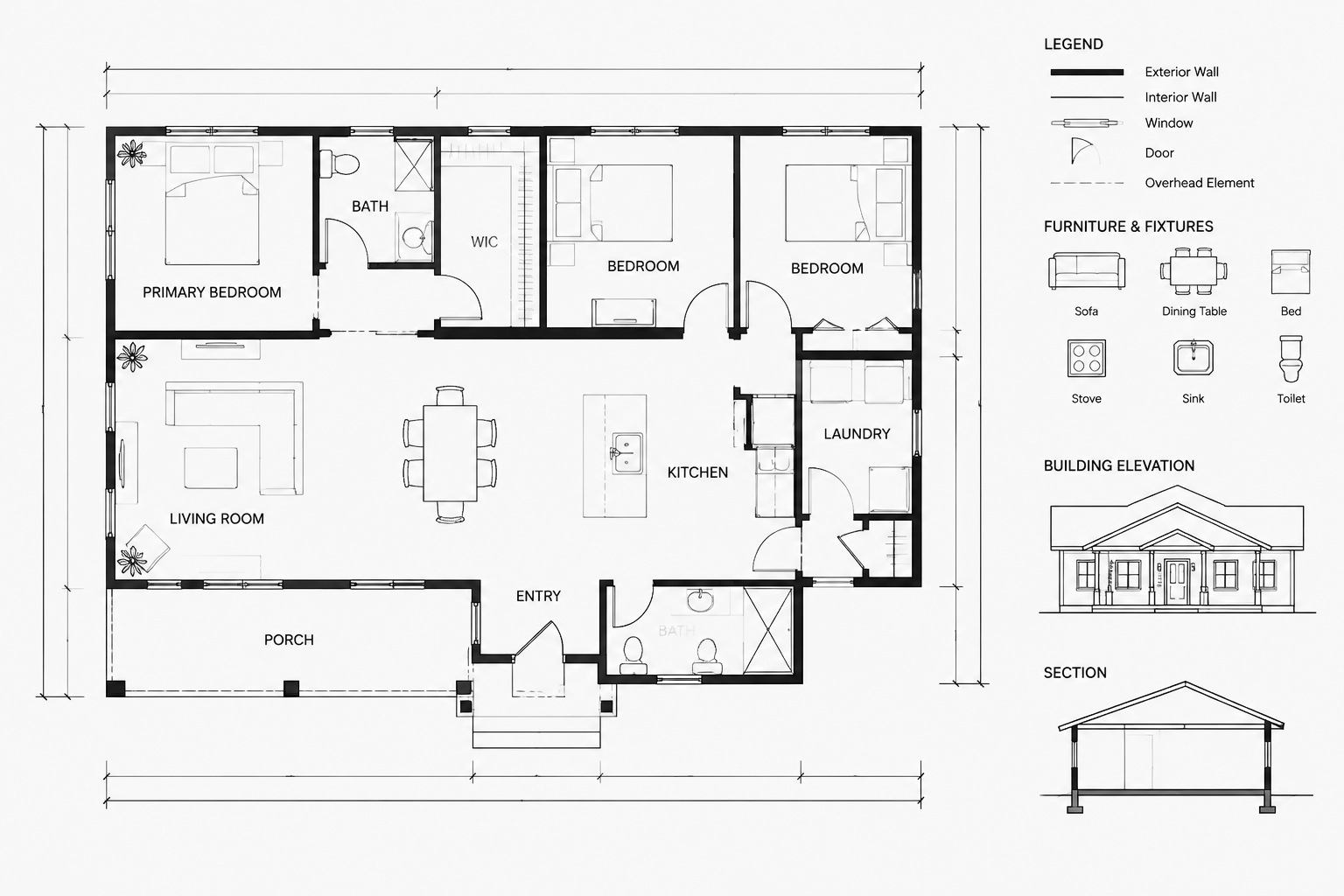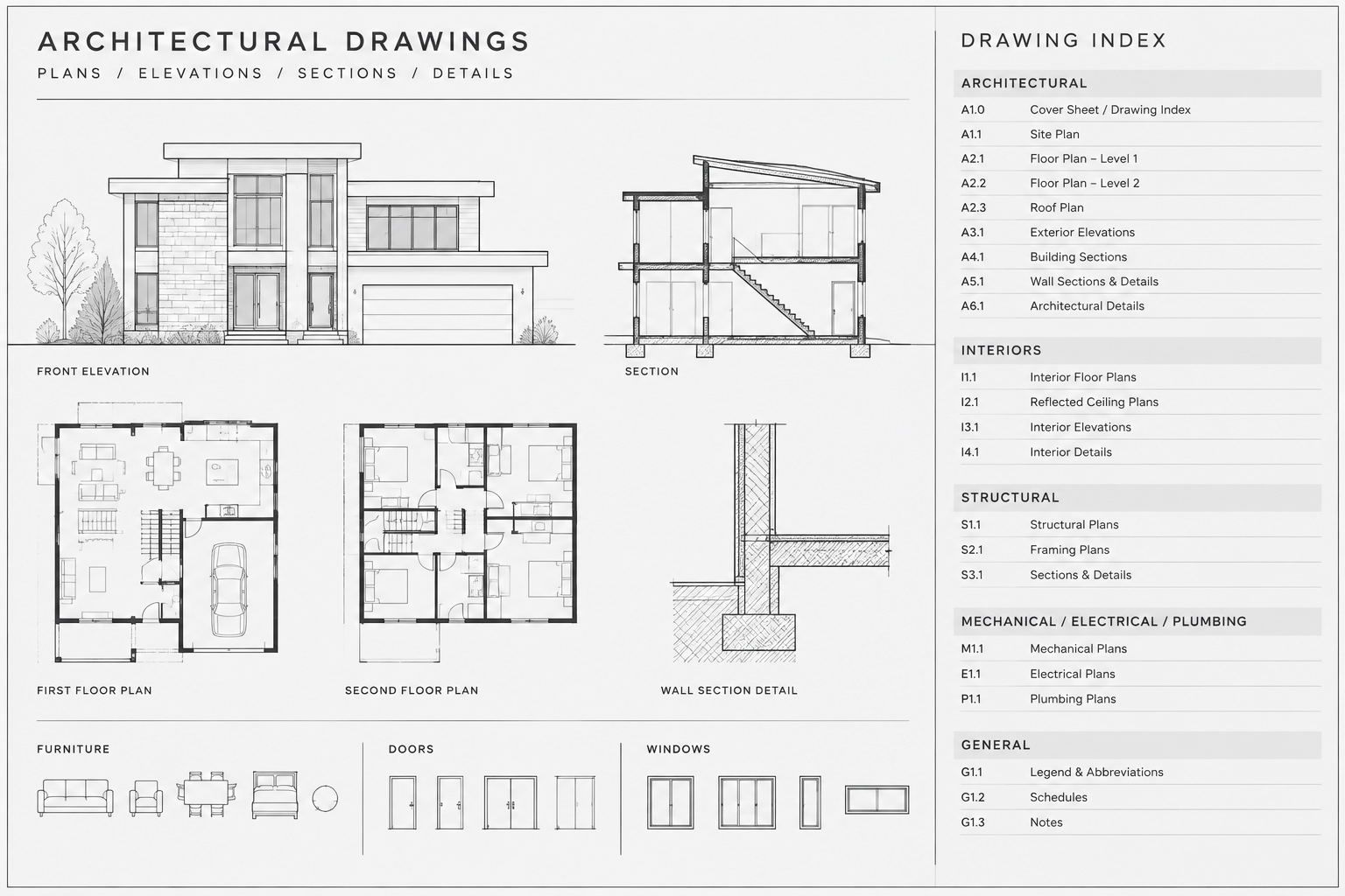
Doors appear simple in a floor plan, but they carry several layers of information. A well-drafted door symbol communicates the wall opening, frame location, leaf position, direction of travel, and relationship to nearby construction. It may also connect to a door tag, schedule, elevation, hardware information, and accessibility review.
Because door symbols are repeated throughout a project, small drafting inconsistencies can quickly become coordination problems. An inaccurate pivot point, an oversized swing arc, or a mirrored block with an unchanged identifier may create conflicts that are easy to miss on a crowded plan. The following workflow explains how to draft door openings and swings clearly without treating a generic CAD block as verified project information.
What a door symbol needs to communicate
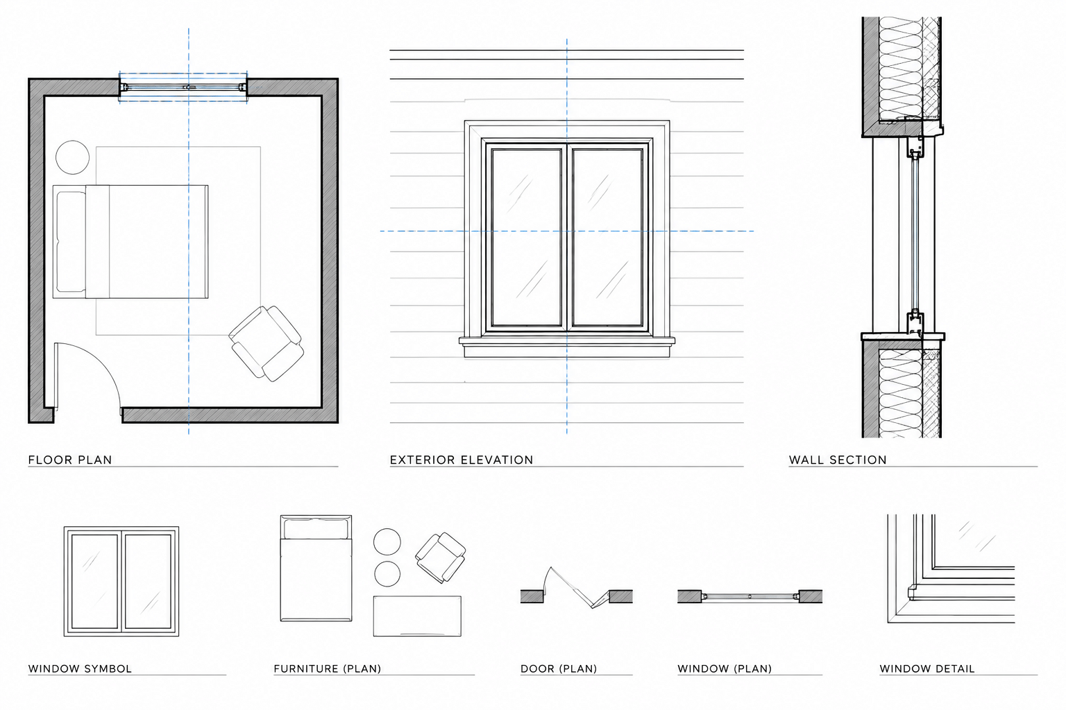
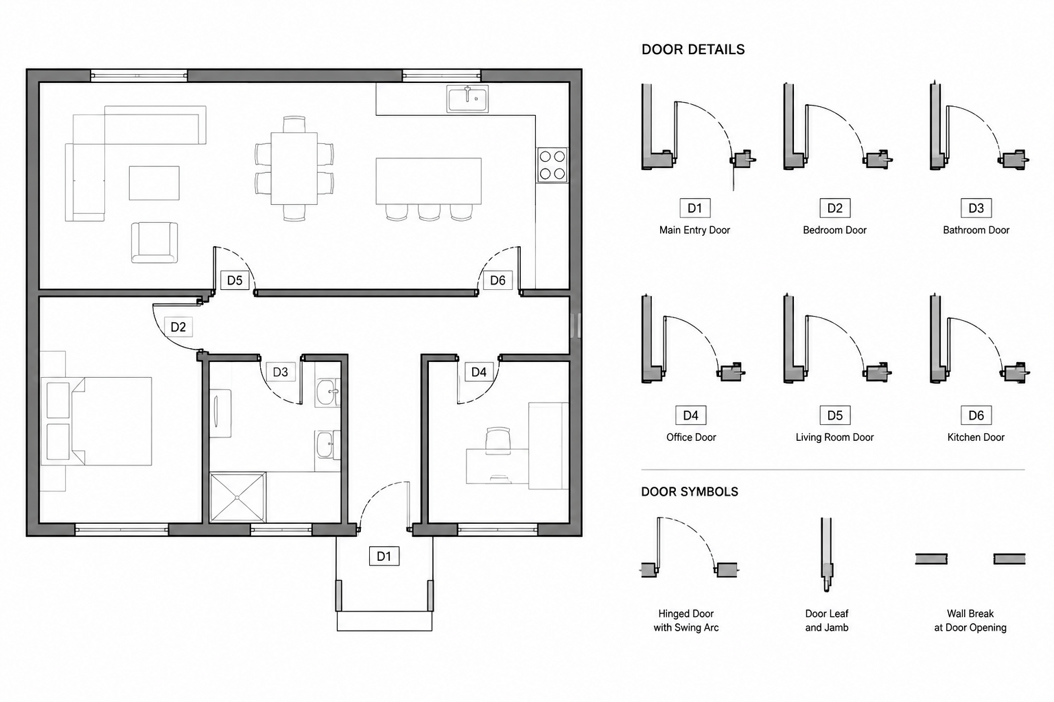
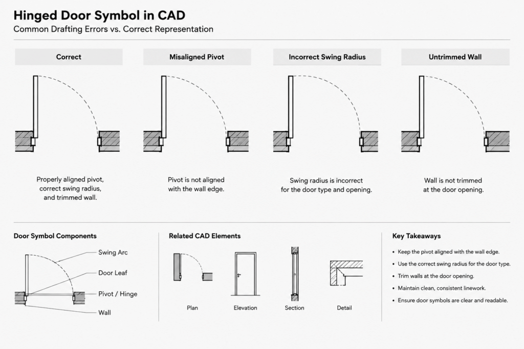
In a typical architectural plan, a hinged door is represented by a leaf shown in an open position and an arc indicating its movement. The surrounding geometry may include the wall interruption, jambs, frame, threshold, and adjacent finishes. The amount of detail shown should suit the drawing scale and purpose.
A general floor plan usually needs a clean, readable symbol rather than a fabrication-level frame profile. Enlarged plans and details can show additional information where it is useful. Trying to place every frame component into the main plan often produces dense geometry that does not plot clearly.
Core graphic components
- Wall opening: The wall geometry should stop or be trimmed at the intended opening.
- Jamb or frame: The frame should align consistently with the selected wall condition and project drafting convention.
- Door leaf: The leaf line should begin at the hinge-side pivot and extend to the latch edge.
- Swing arc: The arc should share the same hinge point and describe the path of the latch edge.
- Door tag: The identifier should remain readable and coordinate with the door schedule or other project data.
Begin with coordinated wall geometry
Draft the wall before inserting the door. Confirm that the wall lines represent the intended construction faces, finish faces, or another documented reference. This matters because a door frame placed against an ambiguous wall can appear aligned in plan while conflicting with dimensions or details elsewhere.
Establish the rough or finished opening according to the project information available to the drawing team. Do not derive a construction opening by guessing from the nominal door leaf. Frame types, installation conditions, clearances, and manufacturer requirements vary. If those details have not been selected, keep the CAD representation appropriately generic and flag the condition for coordination.
Trim or break wall lines cleanly at the opening. Avoid hiding an unbroken wall behind a filled door block. Hidden duplicate geometry makes later revisions difficult and can produce unexpected lines when objects are moved, isolated, or exported.
Place the hinge point deliberately
The hinge point controls both the door leaf and swing arc. It should be located at the intended pivot side of the opening, not merely at the nearest visible wall corner. Depending on the level of detail, the pivot may be represented schematically at the jamb or more precisely relative to the frame.
Use one consistent convention across comparable plans. If some doors pivot from the rough opening corner while others pivot from the face of a detailed frame, swing graphics will look uneven and may imply different opening widths.
Once the pivot is established, draw the leaf in its open position. The leaf length should represent the documented door condition used by the project, rather than an arbitrary scaled line. Keep the closed position implicit unless the office convention or drawing purpose requires it to be shown.
Construct a clean swing arc
The swing arc should be centered on the hinge point and terminate at the latch edge of the open leaf. Its purpose is to communicate movement and spatial conflict, not to imitate a physical object. A simple arc is usually clearer than a thick band or decorative symbol.
Check the following when reviewing the arc:
- Its center matches the leaf pivot.
- Its radius matches the represented leaf length.
- It curves in the correct direction.
- It ends cleanly at the open leaf.
- It does not contain unnecessary duplicate segments.
- Its layer and lineweight remain subordinate to cut walls and major building elements.
Where two door swings overlap, do not automatically alter the arcs merely to make the plan look cleaner. The overlap may reveal a real circulation or operational conflict. Review the design first, then adjust the graphics only if the apparent conflict is caused by schematic representation rather than the proposed condition.
Understand swing direction without relying on visual guesswork
A plan symbol shows which side contains the hinge and the direction in which the leaf opens. Handing terminology, however, can depend on the project convention, viewpoint, door type, and hardware documentation method. Terms that appear obvious to one team may be interpreted differently by another.
For that reason, avoid assigning a handing label based only on a mirrored plan symbol. Determine which side of the door is used as the reference, whether the opening is inward or outward relative to that viewpoint, and how the project hardware information defines the condition. Confirm terminology with the responsible project documentation rather than embedding an assumption into the CAD block.
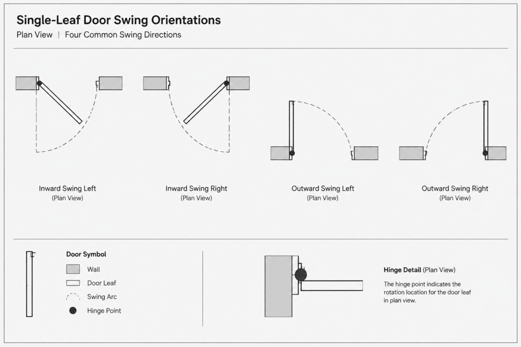
This distinction is especially important for paired leaves, communicating doors, double-acting doors, sliding systems, and openings with specialized hardware. A generic single-leaf swing block may be useful as a drafting starting point, but it does not establish the correct hardware function or code compliance.
Use blocks that support revision
A reusable door block can improve consistency, provided it is built around a logical insertion point. For a hinged door, the hinge pivot is often the most useful base point because it makes rotation and placement predictable. The leaf and arc can then remain geometrically related.
Keep the block content simple. Include only the objects that belong to the repeated symbol. Wall lines, room-specific notes, dimensions, and unrelated tags should normally remain outside the block so they can be edited independently.
Before using a downloaded door block, inspect its units, scale, layers, insertion point, object types, and internal geometry. Confirm that the swing is constructed correctly and that mirrored copies do not contain backward text or misleading attributes. A downloaded DWG symbol is reference geometry, not proof that an opening is suitable for a project.
Mirroring and rotation checks
Mirroring is efficient for creating opposite swing configurations, but it requires review. After mirroring, verify the hinge location, arc direction, frame relationship, tag position, and any text or attributes. Rotation can create similar issues if annotations are nested inside the block.
If a block contains an identifier, do not assume the identifier should be duplicated with every copy. Door numbers typically need to remain unique and coordinated with the schedule. Separating the tag from the geometry can reduce accidental duplication.
Organize door graphics by function
Door geometry should follow the project layer strategy. A useful setup distinguishes permanent building geometry, overhead or beyond information, annotations, and non-plotting construction aids. The exact layer names should match the office or project standard rather than an improvised naming system.
| Graphic element | Drafting consideration |
|---|---|
| Leaf and swing | Keep readable but visually lighter than cut walls. |
| Frame or jamb | Coordinate with the wall and selected level of detail. |
| Door tag | Place on an annotation layer and keep clear of the swing. |
| Threshold | Show only when relevant to the plan or detail. |
| Clearance or review zones | Place on a dedicated layer so they can be managed separately. |
Use layer properties to control plotted appearance instead of assigning arbitrary colors and lineweights to individual objects. This makes global updates easier and helps door graphics remain consistent across referenced files and sheets.
Coordinate tags, dimensions, and schedules
Place the door tag where it is easy to associate with the correct opening. Avoid placing it inside a swing arc if another nearby location is available. On dense plans, a leader or a carefully arranged tag position may be clearer than forcing every identifier into the same relative location.
Dimension openings according to the project’s dimensioning convention. The intended reference might be an opening edge, frame location, wall face, or centerline. Do not mix references without explanation. A visually tidy dimension string can still be misleading if its witness points do not correspond to the construction information.
Review every tagged door against the schedule. Check that identifiers are unique, deleted doors have been removed from both locations, new openings have been added, and paired or unusual configurations are described consistently. Plans, schedules, elevations, and details should tell the same story.
Review nearby conflicts in context
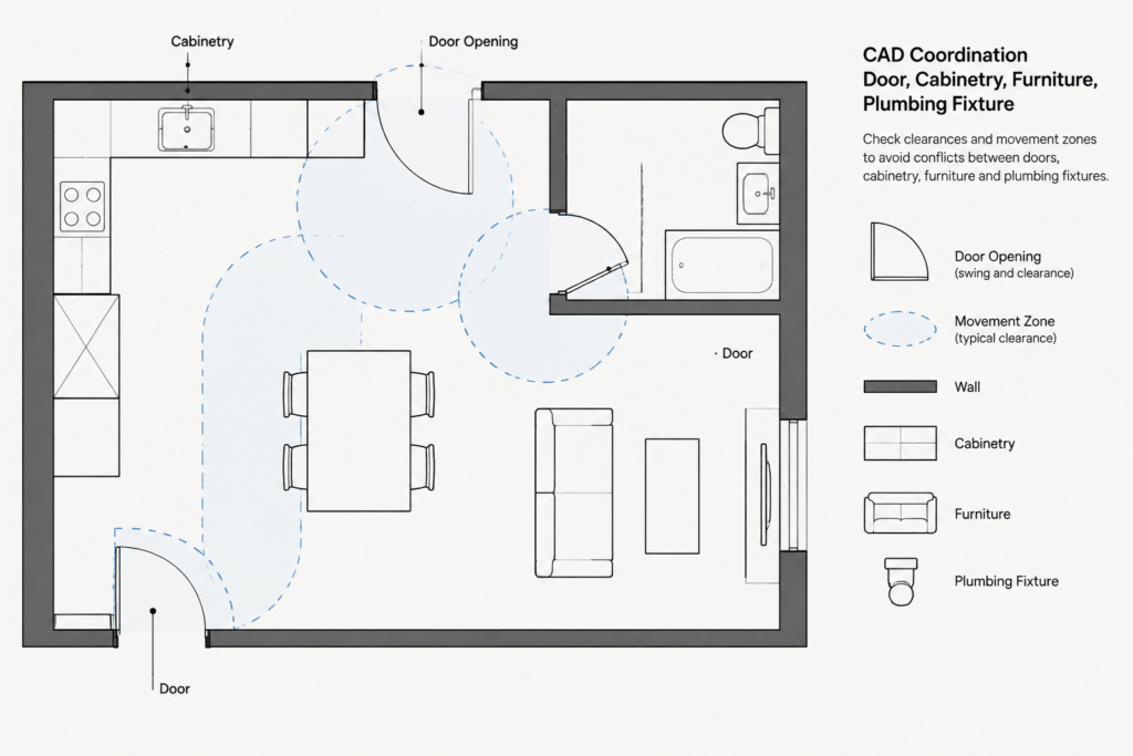
Door swings should be checked against more than walls. Review their relationship to cabinetry, plumbing fixtures, furniture, equipment, controls, railings, level changes, and other doors. Also consider whether a fully open leaf blocks circulation or obscures an important feature.
These checks are design coordination tasks, not automatic proof of compliance. Applicable accessibility, egress, fire-protection, and hardware requirements depend on the project and jurisdiction. Confirm them using current project criteria and qualified review.
Final CAD quality-control checklist
- The wall is genuinely opened rather than concealed behind the block.
- The frame aligns with the intended wall reference.
- The leaf begins at a consistent hinge point.
- The swing arc uses the same pivot and reaches the latch edge.
- The swing direction matches the proposed operation.
- Mirrored blocks contain no reversed annotation.
- Tags are legible, unique, and coordinated with the schedule.
- Door graphics use the correct layers and plot hierarchy.
- Nearby fixtures, furniture, and other leaves have been reviewed for conflicts.
- Unverified block geometry has not been treated as project approval.
A reliable door plan is built from coordinated geometry rather than symbols placed for appearance alone. By controlling the opening, pivot, swing arc, layers, and identifiers as related information, CAD users can produce door drawings that are easier to read, revise, and coordinate throughout the project.