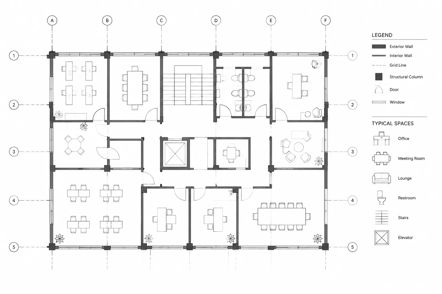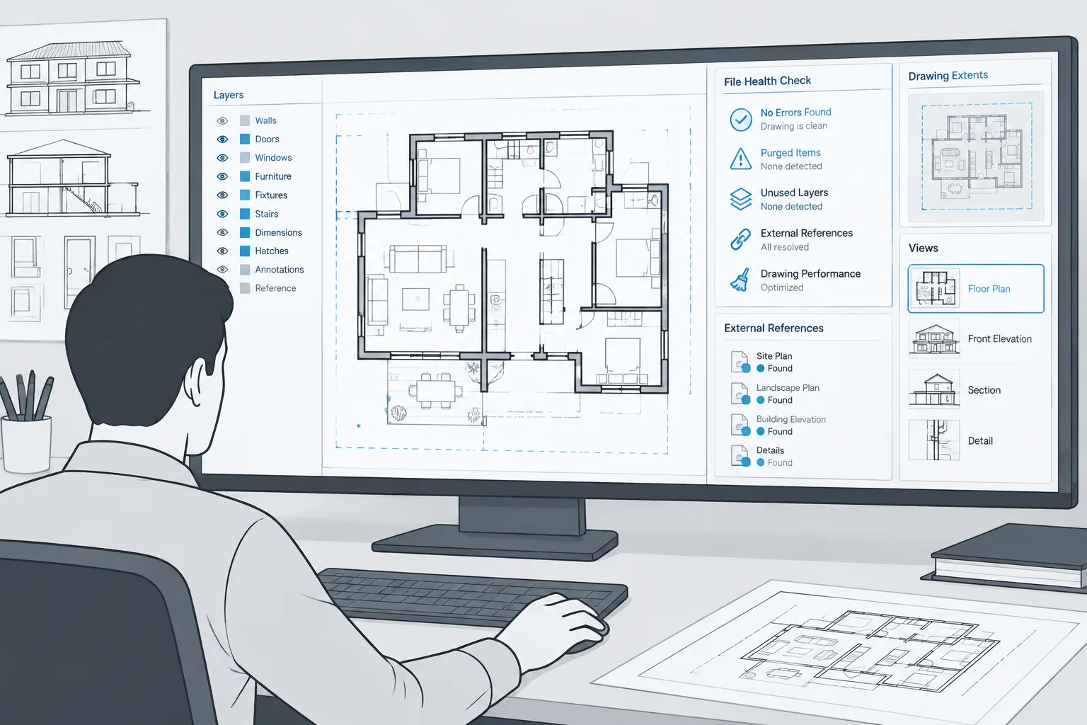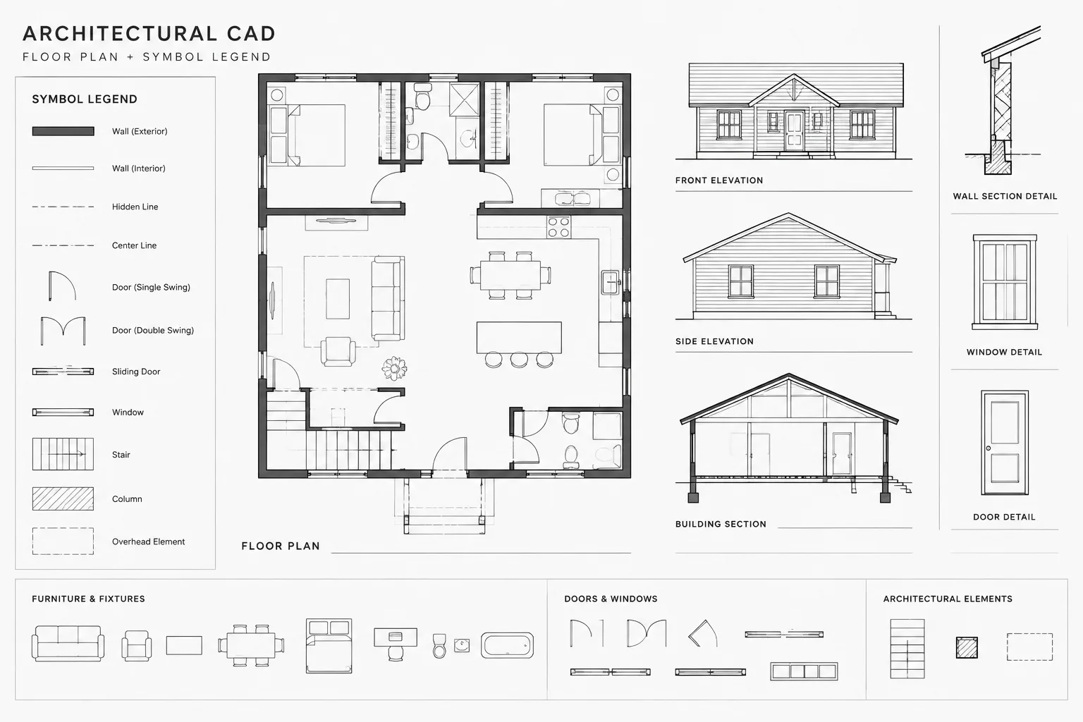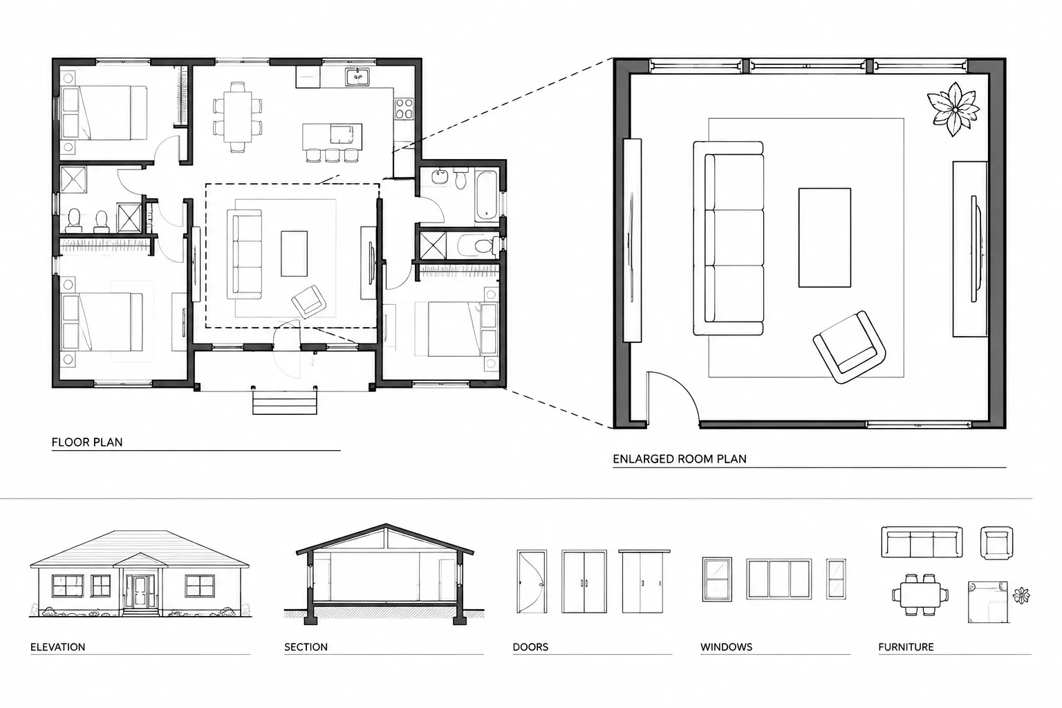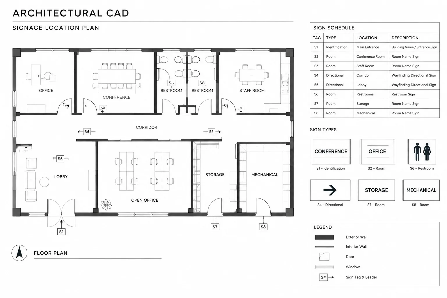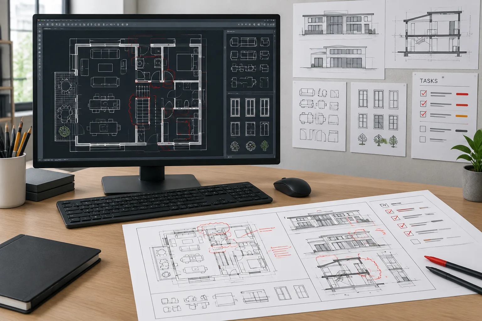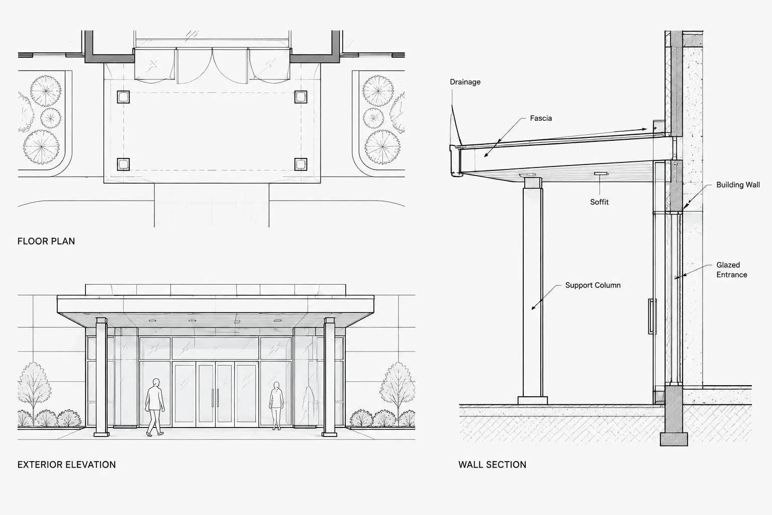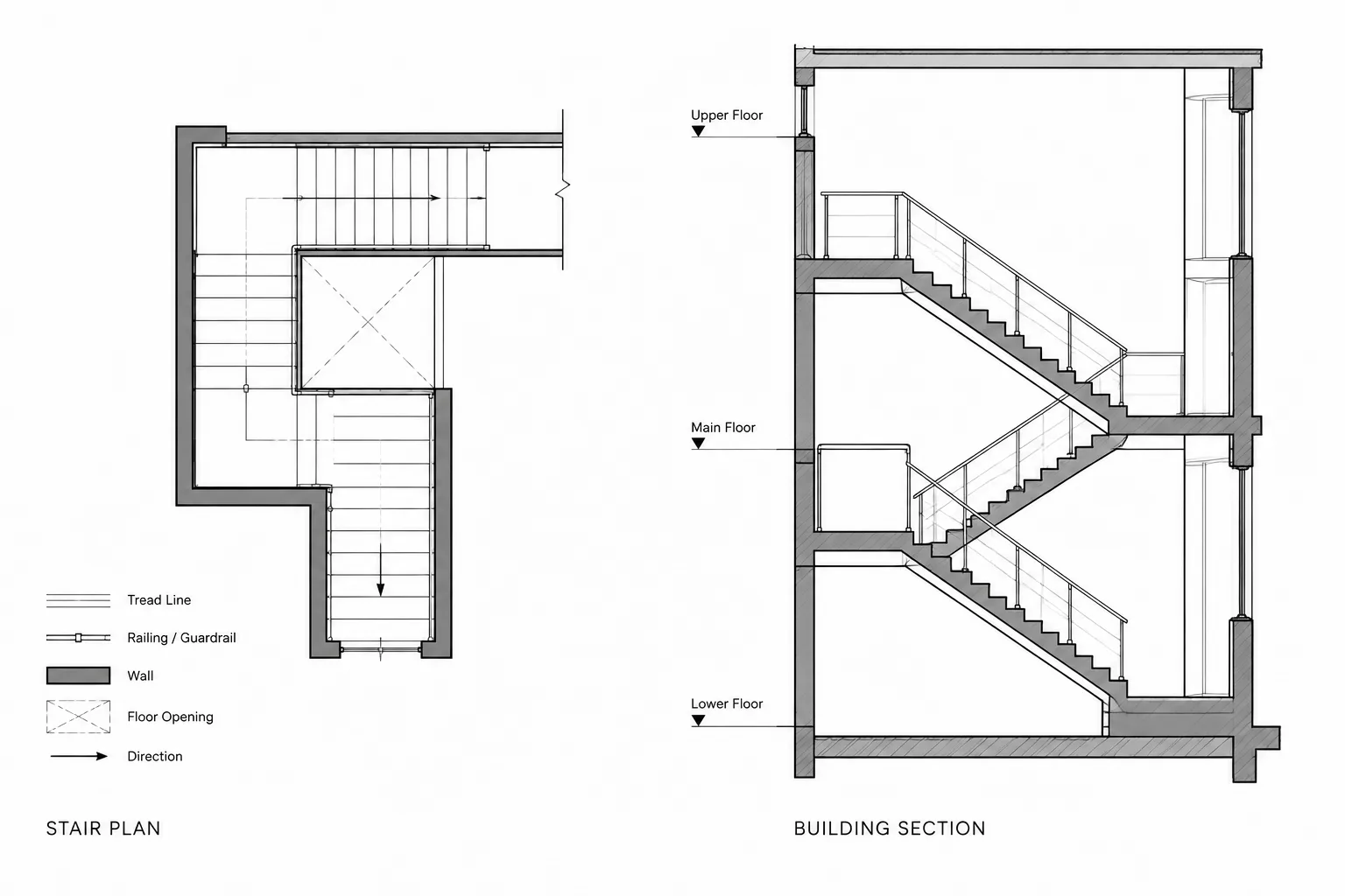
Coordinated stair drawings depend on more than accurately spaced tread lines. Floor levels, landings, openings, structural edges, overhead conditions, and railing geometry must describe the same stair in every view. A change to any controlling element can affect the plan, section, details, and consultant backgrounds.
The workflow below treats stair drafting as a connected CAD process. It explains how to establish control geometry, develop plans and sections from shared information, organize linework, and review the completed views without substituting generic assumptions for project-specific requirements.
Stairs are among the most coordination-intensive elements in an architectural drawing set. A stair must connect known floor levels, fit within its enclosure, align with landings and floor openings, and remain consistent across plans, sections, details, and structural backgrounds. Even when the design is still developing, the CAD geometry should make these relationships easy to check.
This guide presents a practical workflow for drafting and coordinating stair plans and sections in architectural CAD. It focuses on drawing organization and geometric consistency rather than prescribing dimensions. Applicable building codes, accessibility criteria, structural requirements, and project-specific standards must be verified for every real project.
Begin with the vertical relationship
Before drawing individual treads, establish what the stair must connect. Identify the finished floor elevations at the bottom and top, along with any intermediate landing elevations. If the building uses structural levels and finish elevations separately, show or record both relationships clearly.
The total vertical rise is the primary control value. Divide that rise into a practical number of equal risers based on the project criteria, then verify the resulting geometry against applicable requirements. Avoid adjusting one riser independently to force the stair to meet a floor. Unequal risers are difficult to communicate and may create serious construction and safety problems.
Record the design assumptions in a working note or calculation area that does not plot. A simple stair calculation can identify:
- Lower and upper reference levels
- Total vertical rise
- Proposed number of risers
- Resulting uniform riser height
- Number of treads in each run
- Landing elevations
- Direction of travel between levels
These values should be treated as coordinated design information, not merely labels added after the stair has been drawn.
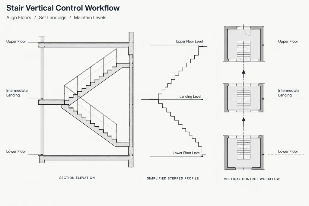
Build a simple stair control diagram
A small control diagram can prevent repeated plan and section errors. Draw a simplified side profile using floor lines, landing lines, and the sloped stair runs. This diagram does not need finish details, nosings, railings, or structural depth. Its purpose is to prove that the stair reaches every required level with consistent risers.
Keep this control geometry on a nonplotting layer or in a designated working area. Use it to generate or check the detailed section. If a floor elevation changes, revise the control diagram first and then update the affected views.
Draft the stair plan from fixed boundaries
Start the plan with the elements that constrain the stair: surrounding walls, shaft boundaries, columns, floor openings, doors, and required landing extents. If these items come from other drawings or consultant files, reference them rather than recreating disconnected copies whenever the project workflow allows.
Lay out the stair centerline or run edges before adding tread lines. This makes it easier to evaluate alignment, clear width, turns, and landing relationships. After the overall arrangement works, divide each run into the required number of equal tread intervals.
Organize repeated tread geometry
Tread lines are repetitive and easy to miscount. Use a controlled array, repeated block, or evenly divided construction geometry according to office practice. Do not rely only on visual spacing. Count the risers from level to level and compare the plan against the stair control diagram.
Keep the tread representation simple at general plan scales. Detailed profiles, nosing shapes, support connections, and finish build-ups usually belong in enlarged sections or details rather than the overall floor plan.
Represent the plan cut clearly
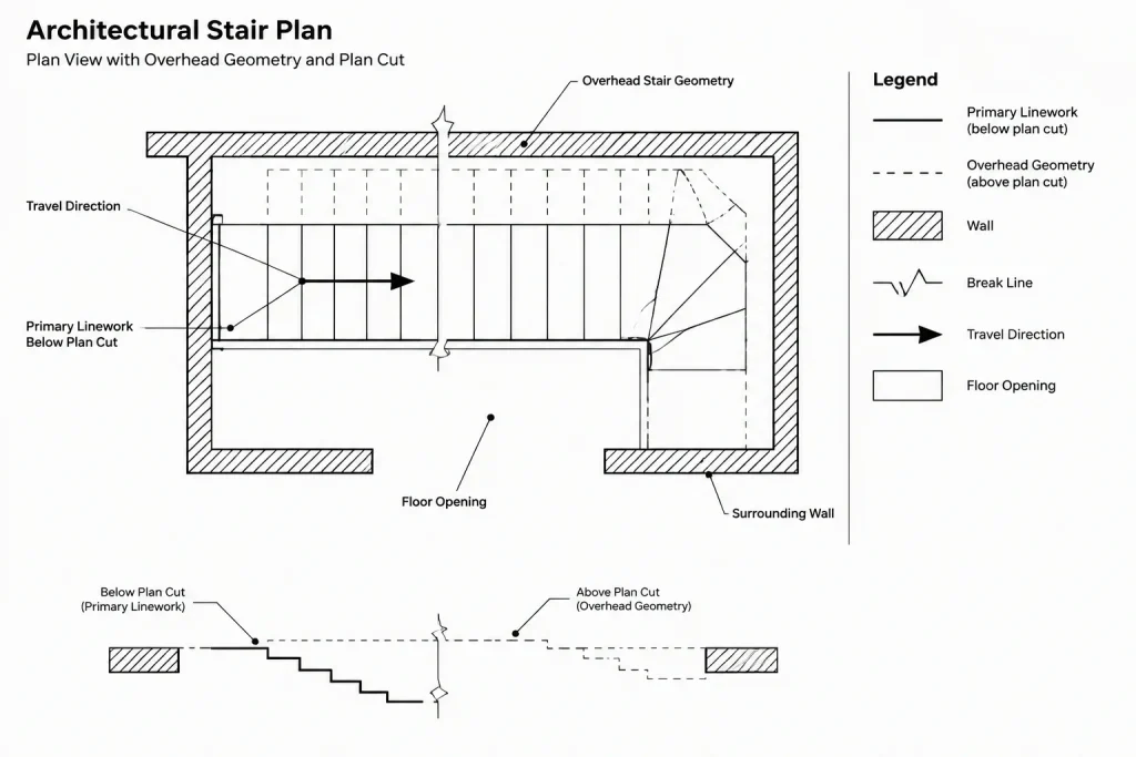
A floor plan does not show the entire stair in the same way. The portion below the plan cut may be shown with primary linework, while elements above the cut are commonly differentiated with overhead or dashed graphics. Exact conventions vary, so follow the project drawing standards and maintain the same logic throughout the set.
Use a break line or other established graphic device where the stair continues beyond the visible portion. Add a direction arrow and an appropriate travel label if required by the office standard. The arrow should communicate movement unambiguously without covering tread lines, dimensions, or room information.
Develop the stair section from the same geometry
The stair section should not be an independently estimated sketch. Project the key locations from the coordinated plan and use the same level data that controlled the riser calculation. Include the lower floor, upper floor, intermediate landings, stair runs, adjacent walls, and the floor opening.
Construct the riser-and-tread profile carefully. Count each riser in the section and compare the count with the plan. A frequent drafting error occurs when the plan counts tread lines while the section is based on risers; those quantities are related but are not automatically identical for every run condition.
Show assembly depth without obscuring the geometry
After the walking line is correct, add the stair assembly beneath it. The assembly may represent a concrete stair, framed construction, a metal stair, or another project-specific system. Its depth and support conditions must come from the selected construction and structural coordination, not from a generic CAD block.
Where finishes occur above the structural stair, distinguish the finished walking surface from the supporting construction. Check that the finished floor and finished landing elevations remain coordinated when material thicknesses change.
Use the section to test vertical clearance
Stair sections are essential for evaluating clearance below floors, landings, beams, soffits, and sloping runs. Show the controlling overhead construction accurately and identify the area where clearance is most limited. Do not assume that checking a single point is sufficient when a beam edge, sloped underside, or changing finish thickness affects the available space.
Any required clearance must be evaluated against the governing project criteria. The CAD drawing should make the controlling geometry visible so that the design team can verify it.
Coordinate the floor opening and structure
The stair opening is shared information between architectural and structural drawings. Compare its edges with stair runs, landing supports, wall framing, beams, slab edges, and required finish zones. A plan that shows only the stair without the actual opening can conceal conflicts.
Coordinate at least the following items:
- Opening length, width, and location relative to grids or walls
- Landing support and connection zones
- Beams or slab edges near the upper run
- Structural thickness beneath landings and flights
- Wall construction around the enclosure
- Finish build-ups at floors and landings
- Potential conflicts with ducts, piping, lighting, or ceiling construction
When consultant geometry changes, review both the plan opening and the stair section. Updating only one view can leave a hidden discrepancy.
Add railings after the primary stair geometry is stable
Handrails and guards should follow the coordinated stair and landing edges. Place them only after the runs, landings, walls, and openings are sufficiently established. This reduces the risk of carefully drafting railing geometry around a stair that later changes.
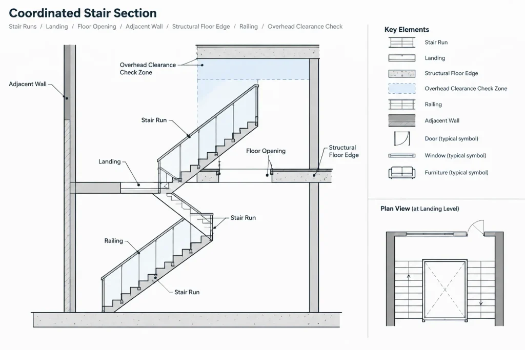
In plan, distinguish wall-mounted handrails from guards or open-side railings where that distinction matters. In section or elevation, show continuity at landings, transitions, returns, extensions, and interruptions as required by the design. Avoid using a generic railing block as proof that the assembly satisfies project requirements.
Use layers that support view control
Stair drawings benefit from separating primary geometry from annotation and overhead information. The exact names should follow the project CAD standard, but useful functional categories include:
| Drawing content | Reason to separate it |
|---|---|
| Stair outlines and tread lines | Controls the main plan and section representation |
| Overhead or beyond-cut geometry | Allows a distinct linetype and visibility setting |
| Handrails and guards | Supports independent coordination and graphic control |
| Floor openings and slab edges | Clarifies architectural and structural coordination |
| Levels, dimensions, and notes | Keeps annotation separate from model geometry |
| Nonplotting construction lines | Preserves control geometry without printing it |
Assign object properties consistently through the project layer system. Excessive object-level overrides make it harder to understand why lines appear differently across viewports and sheets.
Annotate information where it is best understood
Plan dimensions should locate the stair, landings, opening, and surrounding walls. The section should communicate vertical levels, run relationships, assembly depths, and critical overhead conditions. Avoid repeating every dimension in both views unless the repetition serves a clear coordination purpose.
Stair tags or notes may identify the stair, direction of travel, connected levels, and references to enlarged views or details. Keep identifiers consistent across plans, sections, schedules, and detail callouts. If one stair serves several levels, make the limits of each referenced view clear.
Run a cross-view quality-control check
Complete the stair review by comparing all related drawings side by side rather than checking each sheet independently.
- Confirm that plan and section contain the same number of risers.
- Verify that every landing elevation agrees with the level information.
- Check that stair and opening boundaries align in plan.
- Compare wall, slab, beam, and soffit positions with the section.
- Verify that overhead linework follows the project convention.
- Check railing continuity and open-edge conditions.
- Review door swings and circulation at landings.
- Confirm that detail and section callouts point to current views.
- Inspect the plotted sheet for crowded notes, hidden tread lines, and weak lineweight hierarchy.
A reliable stair drawing begins with vertical control, not decorative detail. When plans and sections share the same levels, riser count, opening geometry, and reference information, revisions become easier to manage and coordination problems are more likely to be found before issue.
Manage stair revisions in a controlled order
Stair coordination becomes more reliable when revisions follow a consistent hierarchy. Begin with the source information that caused the change, such as a floor level, landing position, wall boundary, structural opening, or assembly depth. Update the control geometry before editing presentation linework or annotations.
A practical revision sequence is:
- Confirm the controlling information. Identify whether the change originates in the architectural design, structural background, finish build-up, or another coordinated system.
- Revise the vertical control. Recheck connected levels, landing relationships, and uniform riser logic.
- Update primary plan geometry. Adjust runs, landings, openings, walls, and circulation relationships.
- Update the section. Project the revised locations and verify the stair profile against the same control information.
- Revise dependent elements. Review railings, overhead graphics, break lines, dimensions, notes, and callouts.
- Compare the plotted views. Confirm that lineweights, linetypes, labels, and references remain readable after the geometry changes.
This order helps prevent a common CAD problem: correcting the visible stair while leaving outdated construction lines, opening boundaries, annotations, or referenced details elsewhere in the drawing set.
Separate design proof from drawing presentation
Working geometry proves that the stair connects correctly. Presentation graphics communicate that solution on the issued sheet. Keeping these purposes distinct allows the drafter to retain useful control lines and calculation notes without crowding the plotted view.
Before issue, verify that nonplotting information is properly controlled and that required information has not accidentally been placed on a hidden or nonplotting layer. A clean sheet should result from deliberate layer and viewport management, not from deleting the geometry used to coordinate the stair.
Treat consultant backgrounds as coordinated references
Referenced structural or building-services information should be checked whenever it is updated. Do not assume that a revised background preserves the previous opening, beam, slab, soffit, or routing conditions. Overlay or compare the current files, identify what changed, and review the effect in both plan and section.
The architectural drawing remains a communication document rather than proof of structural adequacy or code compliance. Final stair geometry, construction, clearances, guards, handrails, and related requirements must be verified by the responsible project professionals against the applicable criteria.
Frequently Asked Questions
Why should a stair plan and section use the same control geometry?
Shared control geometry reduces discrepancies between views. Levels, landing positions, run limits, and opening edges can be checked from one coordinated basis instead of being estimated independently in each drawing.
Why can tread-line counts cause confusion?
A tread line in plan is not automatically equivalent to the complete riser count between connected levels. Run conditions and landings affect how the stair is represented, so the risers should be counted and checked directly in the section and control diagram.
What should be updated first when a floor elevation changes?
Revise the vertical control information first. Then recheck the riser calculation, landing elevations, plan geometry, section profile, floor opening, overhead conditions, railings, and annotations affected by the change.
Should railing blocks be inserted before the stair is finalized?
Railings are better developed after the primary runs, landings, walls, and openings are stable. A generic block may help with graphic development, but it does not verify continuity, transitions, support conditions, or compliance with project requirements.
What information belongs in the plan rather than the section?
The plan is generally best for locating the stair, landings, opening, walls, direction of travel, and circulation relationships. The section is better suited to levels, vertical relationships, assembly depth, overhead construction, and clearance evaluation.
How should structural changes near a stair be reviewed?
Compare the current structural background with the architectural plan and section. Review opening edges, slabs, beams, landing supports, assembly depths, and any condition that could affect the stair profile or available space.