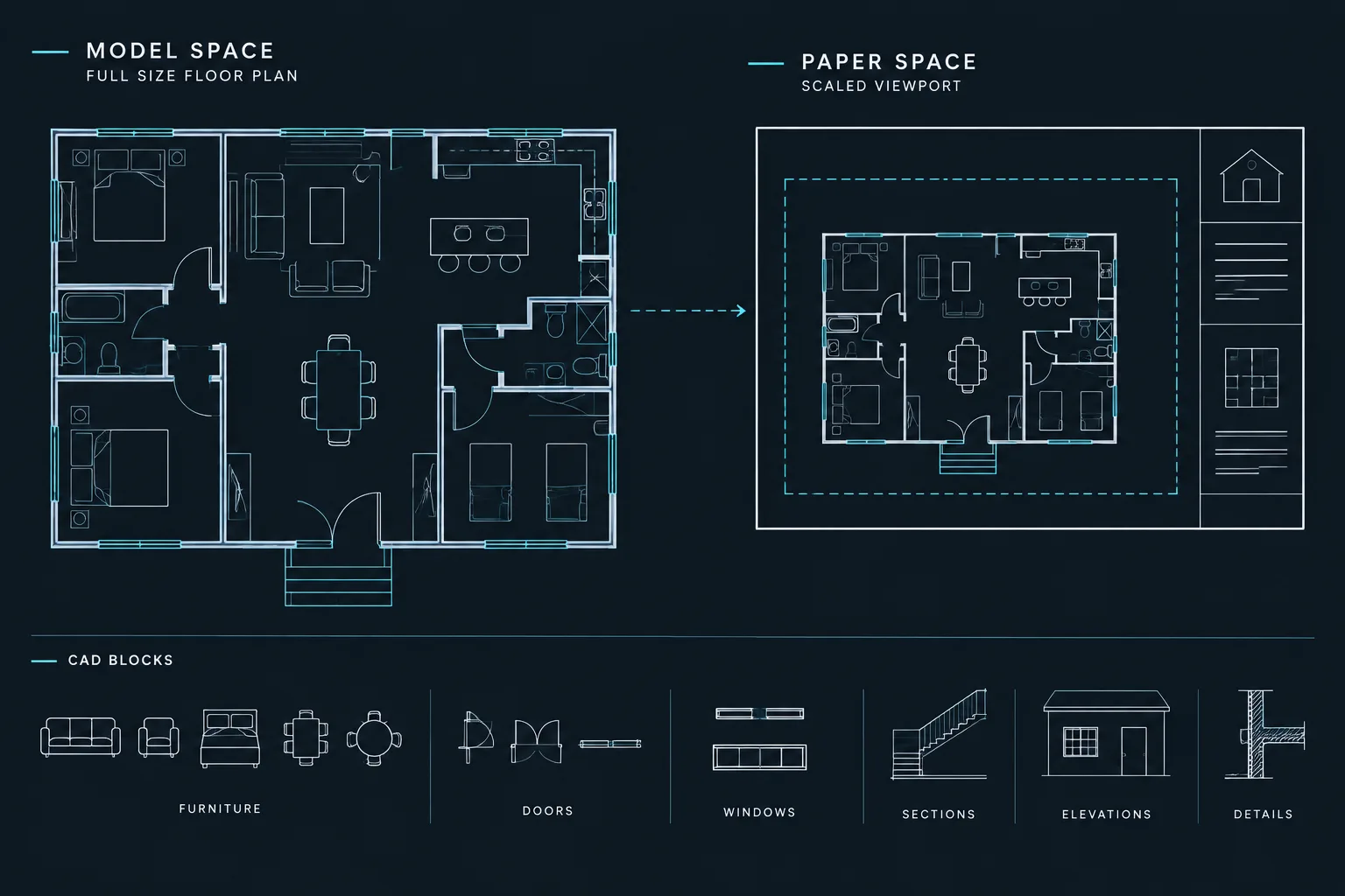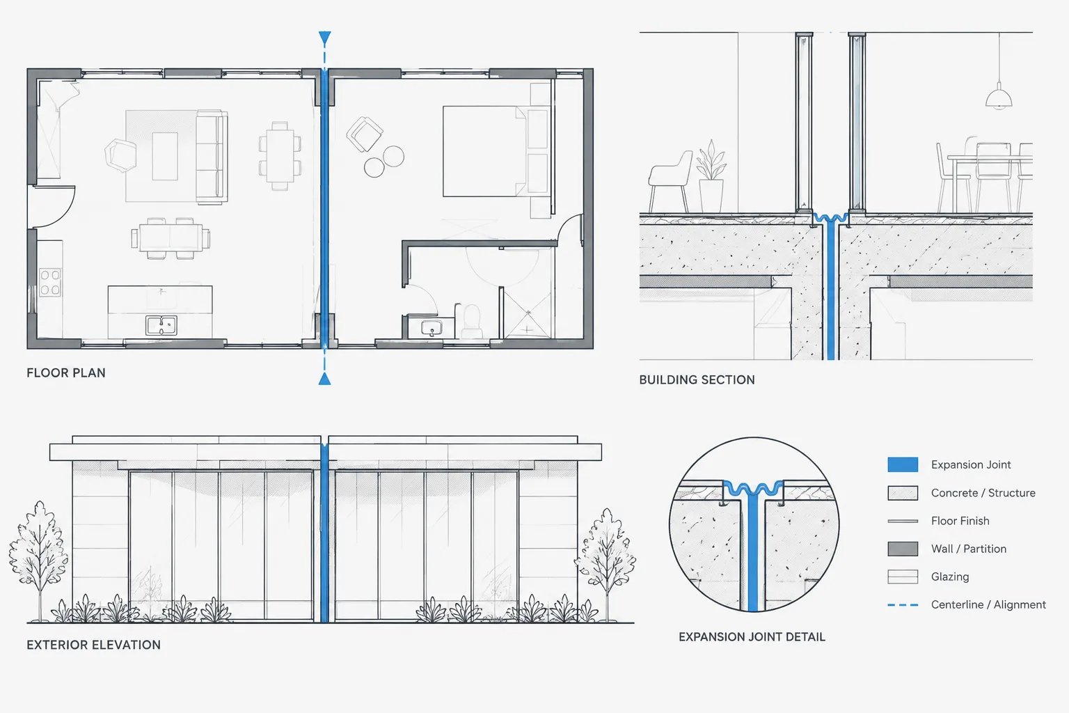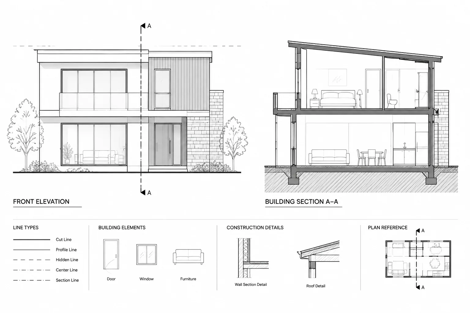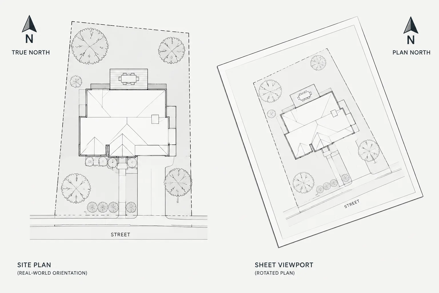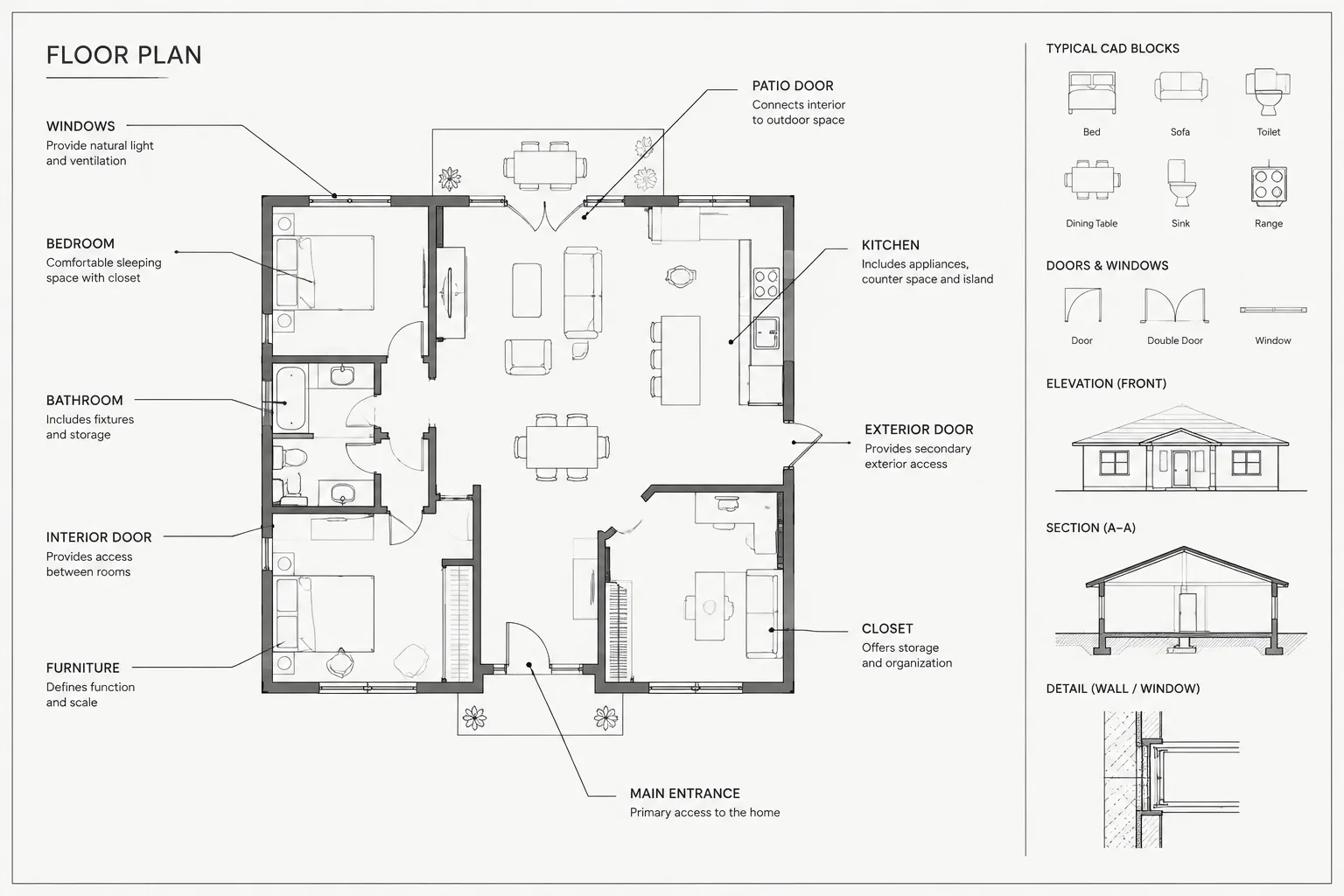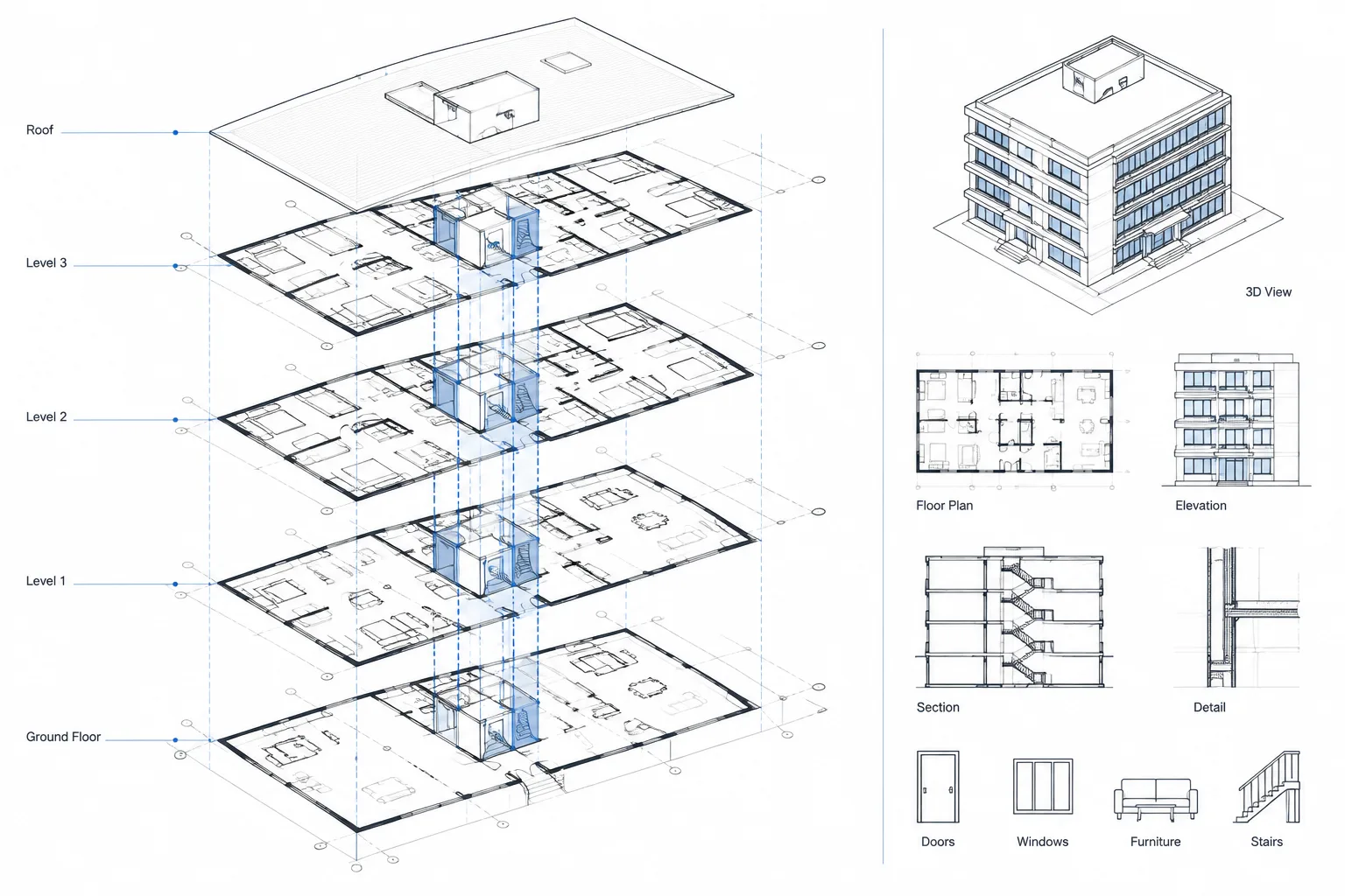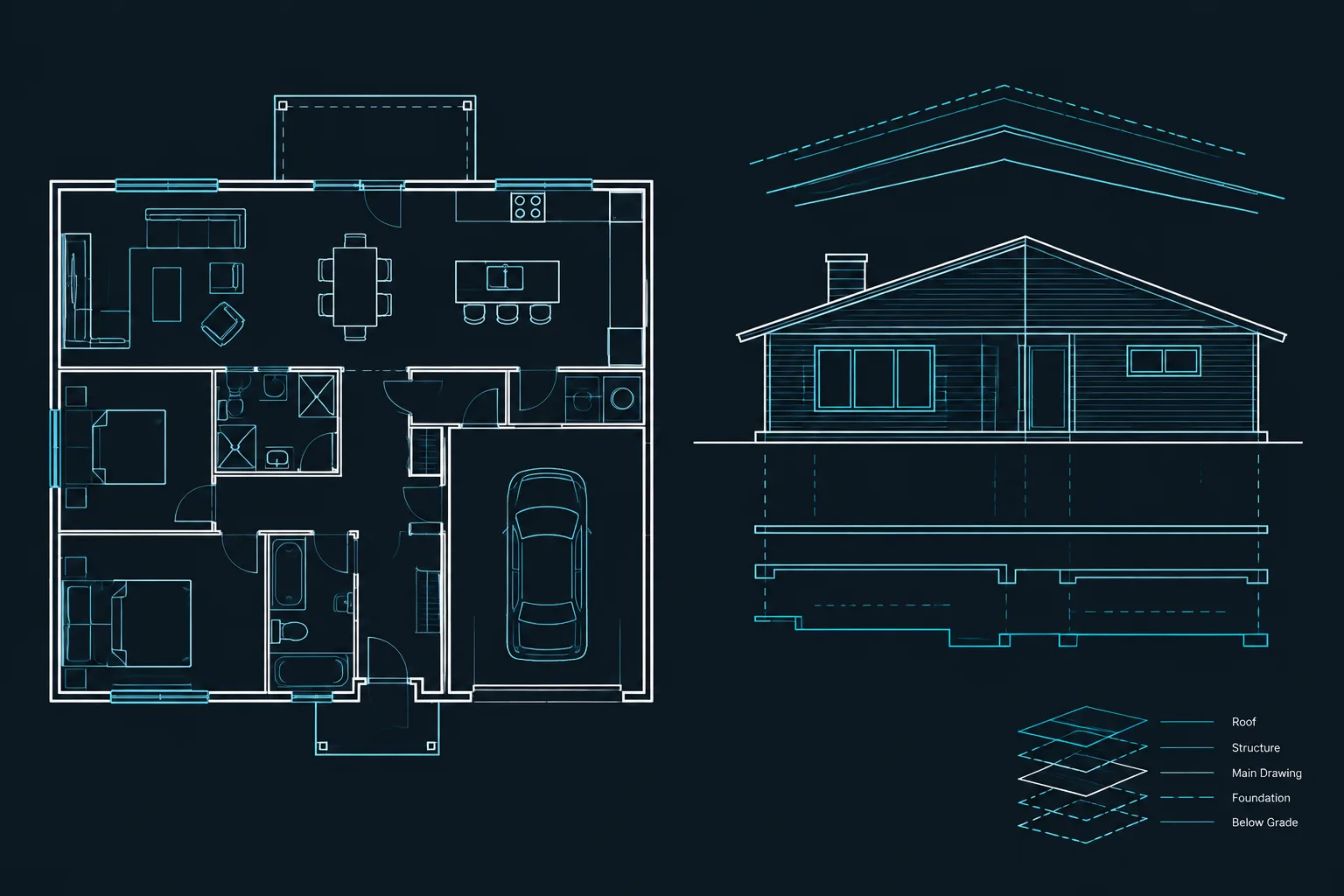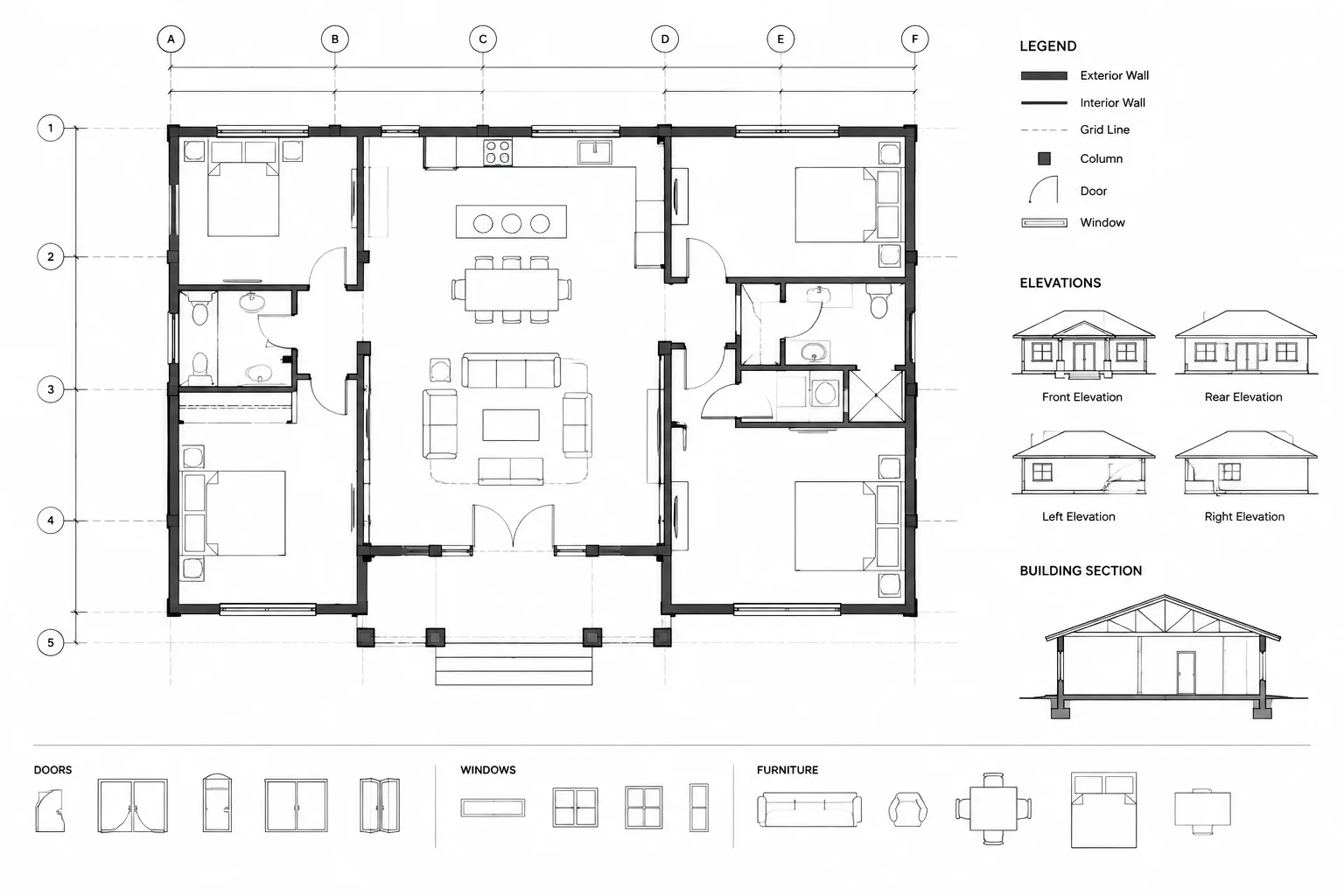
Drafting slab edges and depressions requires more than tracing a boundary. Each line must communicate whether the condition is a slab perimeter, step, recess, depression, or opening, while remaining coordinated with finishes, walls, thresholds, drainage, equipment, and structural backgrounds.
This guide explains a practical architectural CAD workflow for defining the condition, organizing its geometry, documenting elevation relationships, and checking related plans and sections. It also highlights where architectural intent should stop and structural engineering information should begin.
Slab edges and depressions often look simple in plan, but they affect several parts of an architectural drawing set. A change in slab geometry may relate to exterior walls, floor finishes, waterproofing, drainage, thresholds, structural framing, or equipment installation. If the condition is shown differently in the floor plan, structural background, and detail, it can create uncertainty during coordination and construction.
A reliable slab edge and depression CAD drafting workflow separates design intent from structural definition. The architectural drawings should clearly communicate the required location, extent, elevation relationship, and finish consequence without implying unverified structural design. The structural drawings should define reinforcement, thickness, support, and other engineering requirements.
Understand the Conditions Before Drafting
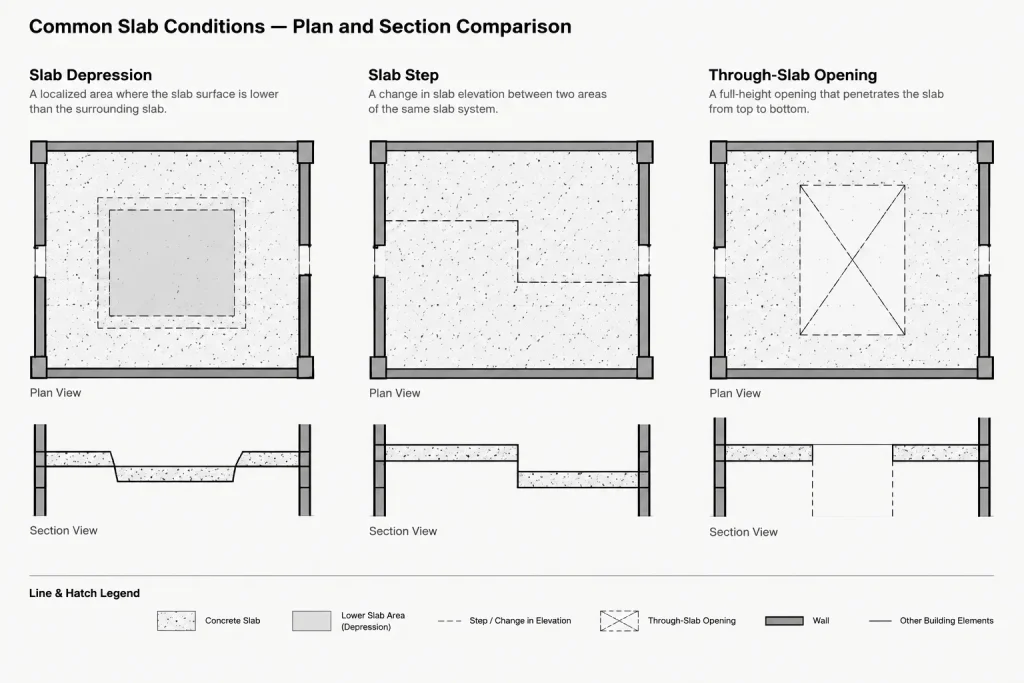
Start by identifying exactly what changes in the floor assembly. The outline visible in plan might represent one of several different conditions:
- Perimeter slab edge: The outside boundary of a concrete slab or structural floor plate.
- Slab step: A change in the elevation of the structural slab between adjacent areas.
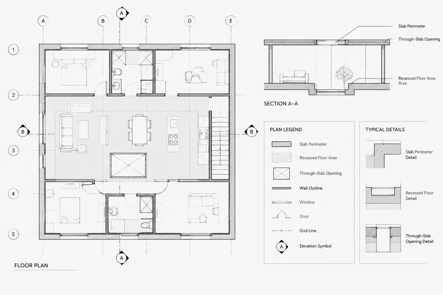
- Slab depression: A lowered region intended to receive a thicker finish assembly, waterproofing system, equipment base, or another coordinated component.
- Local recess: A limited pocket or lowered area associated with a fixture, mat, track, pan, or piece of equipment.
- Slab opening: A void extending through the slab rather than a lowered area within it.
- Edge thickening or structural drop: A structural condition that should be defined and confirmed by the structural engineer.
These conditions should not be represented by one generic dashed rectangle. A depression is not an opening, and a finish transition is not necessarily a structural slab step. Confirm what is changing before selecting graphics or notes.
Establish the Controlling References
Review the latest architectural floor plan, structural plan, finish information, equipment layouts, and relevant sections. For exterior conditions, also check wall sections, grading information, paving transitions, and waterproofing details.
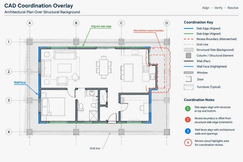
The architectural model or base plan usually controls room arrangement, wall location, finish intent, and fixture placement. The structural background typically controls the engineered slab boundary and framing configuration. Differences between these sources should be treated as coordination issues rather than silently corrected in only one file.
When working with external references, keep architectural and structural information visually distinguishable. A screened structural background can make slab geometry available for coordination without allowing it to compete with the architectural plan.
Build Clear Plan Geometry
Trace the actual extent
Use closed polylines or other clean, continuous geometry for the boundary of a depression or recess. Avoid assembling the outline from overlapping fragments unless the condition truly requires separate segments. Closed geometry is easier to check, hatch, revise, and compare against referenced drawings.
Place boundaries according to the controlling construction relationship. Depending on the condition, the limit may align with a wall face, finish face, curb, frame, waterproofing termination, fixture footprint, or structural grid. Do not assume that the edge automatically follows the nearest architectural object.
Differentiate visible and concealed edges
A slab boundary visible in the completed plan may use a different line convention from an edge concealed below flooring or construction. Hidden or overhead graphics can help, but they should be applied consistently with the office drawing standard and the rest of the set.
Do not rely on linetype alone. Add a concise label or elevation indicator where the meaning would otherwise be ambiguous. This is especially important when a depression and a through-opening could appear similar at the plan scale.
Avoid duplicated boundaries
Slab edges frequently coincide with walls, curbs, or finish transitions. Stacking multiple heavy lines at the same location can make the printed drawing look irregular. Decide which object carries the primary visible line and whether secondary geometry should be lighter, hidden, clipped, or omitted from that specific view.
Use Layers That Describe Purpose
Slab-related objects should be separated according to their role rather than placed together simply because they are concrete-related. A practical layer structure may distinguish among:
- Architectural slab boundaries
- Slab depression or step outlines
- Through-slab openings
- Hidden slab geometry
- Hatches or poche
- Elevation markers and symbols
- Notes, dimensions, and references
- Structural background information
The exact layer names should follow the project or office system. The important point is that users can control graphics without turning off unrelated information. Separating openings from depressions also reduces the risk of misreading the drawing during later revisions.
Communicate Elevation Relationships Carefully
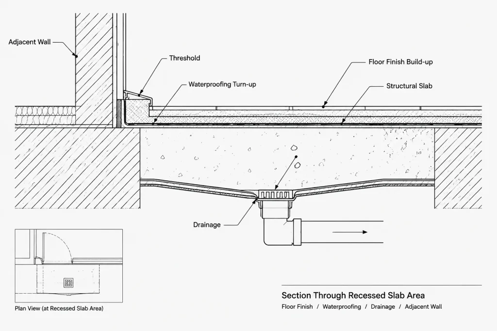
A slab note should make clear whether it refers to the structural slab, the finished floor, or another defined datum. Mixing finish elevations with top-of-slab elevations is a common source of coordination errors because different floor assemblies may create different relationships between the two.
Use the project’s established elevation notation and datum conventions. If the exact elevation has not been confirmed, do not guess. Mark the condition for coordination and identify the responsible discipline or source drawing.
Where a sloped surface occurs within a depression, coordinate spot elevations, slope arrows, drains, and threshold conditions. The plan should indicate enough information to locate the geometry, while a section or detail should explain the vertical assembly.
Coordinate Depressions with Finishes and Equipment
Many slab depressions exist because another system needs space. Check the depression against the actual assembly rather than treating it as an isolated structural shape.
| Related item | Coordination question |
|---|---|
| Floor finish | Does the finish build-up require a structural recess, or only a finish transition? |
| Waterproofing | Where does the membrane turn up, terminate, or cross the slab step? |
| Drainage | Is the low area coordinated with drains, slopes, and adjacent thresholds? |
| Doors and frames | Does the slab condition conflict with the frame, sill, swing, or required transition? |
| Casework and fixtures | Does the recess extend beneath components that require level support? |
| Equipment | Has the required footprint been verified against current manufacturer and consultant information? |
| Structural framing | Can the proposed edge or depression be accommodated by the engineered system? |
A depression should not automatically match the visible size of a fixture or finish. Installation clearances, support conditions, waterproofing, and perimeter detailing may affect its actual extent. Use verified project information.
Add Dimensions and References Without Overloading the Plan
Dimension slab geometry from stable references such as grids, primary wall faces, or established control lines. Avoid long chains based on movable furniture, finish patterns, or temporary layout objects.
Dimension enough information to locate and size the condition, but do not repeat the same measurements in several views unless the project workflow requires it. Repeated values can fall out of coordination. For complex conditions, use a detail reference instead of crowding the floor plan with vertical construction information.
A useful plan annotation may combine a condition label, an elevation relationship, and a section or detail reference. Keep terminology consistent across plans, schedules, sections, and consultant markups.
Show the Vertical Condition in Section
Plan graphics establish location, but sections explain what the slab change actually does. A coordinated section can show the structural slab, finish build-up, adjacent wall or curb, waterproofing relationship, and the difference between finish level and slab level.
Choose a section cut that passes through the meaningful part of the condition. A section through an empty portion of a recess may miss the threshold, drain, equipment support, or wall interface that caused the depression in the first place.
Keep structural information appropriately referenced. Architectural details may show intended interfaces, but reinforcement, structural thickness, and engineered support should come from the responsible structural documentation.
A Practical CAD Workflow
- Collect current backgrounds. Confirm that architectural, structural, equipment, and finish information is current before drafting.
- Classify each condition. Decide whether it is an edge, step, depression, recess, opening, or structural feature.
- Create clean boundaries. Draft continuous geometry on purpose-specific layers.
- Apply graphic hierarchy. Distinguish primary edges, concealed limits, hatches, and reference information.
- Add controlled annotation. Identify the condition, datum basis, and related detail without entering unverified values.
- Check vertical relationships. Review sections, finishes, thresholds, slopes, and waterproofing transitions.
- Compare with structural drawings. Flag mismatched edges, openings, supports, or elevations for resolution.
- Test the plotted sheet. Verify that boundaries, hidden lines, and notes remain legible at the intended sheet scale.
Quality-Control Checks Before Issue
- Confirm that every depression is distinct from a through-opening.
- Check that slab geometry aligns with the current wall and grid layout.
- Verify that plan notes and section details use the same terminology.
- Confirm whether each elevation refers to finished floor or structural slab.
- Review door thresholds, exterior transitions, and accessible route interfaces with the project team.
- Check that drains and slopes fall within the intended depressed area.
- Look for doubled lines where slab edges overlap walls or curbs.
- Confirm that obsolete structural backgrounds or superseded equipment footprints are not displayed.
- Review layer visibility in every affected viewport.
- Plot or export a test sheet to catch weak hidden lines, dense hatches, and masked annotations.
Keep Design Intent and Structural Definition Separate
The architectural drawing should explain where a slab condition is required and how it relates to rooms, finishes, openings, and assemblies. It should not invent structural solutions. When the engineering definition is incomplete, show the architectural requirement clearly and track the unresolved item through the project’s coordination process.
Well-drafted slab edges and depressions are easy to locate, difficult to misinterpret, and consistent across plans and sections. Clean geometry, disciplined layers, explicit elevation references, and careful consultant coordination make these small plan elements far more reliable.
Use a Clear Source Hierarchy During Coordination
When drawings disagree, avoid adjusting geometry merely to make the files appear aligned. First identify which document controls the room layout, structural boundary, finish requirement, equipment footprint, or vertical relationship. Record the discrepancy and obtain confirmation from the responsible project team member before treating the change as resolved.
This source hierarchy is especially important when a depression is driven by architectural finishes but must be accommodated by the structural system. The architectural plan can identify the required location and intended relationship, while the structural documentation defines the engineered construction.
Manage Revisions as Coordinated Changes
A revised slab boundary can affect more than the object being edited. After changing a slab edge, depression, or recess, review associated dimensions, elevation symbols, section cuts, detail references, hatches, room finishes, door conditions, equipment layouts, and consultant backgrounds.
Keep superseded geometry from remaining visible beneath the current design. Old outlines, copied annotations, and disconnected hatch boundaries can make a drawing look coordinated while still communicating conflicting information.
Review the Drawing as a Construction Communication Tool
Before issue, read the plan without relying on personal knowledge of the model. A reviewer should be able to distinguish a lowered slab area from an opening, understand the referenced datum, locate the condition from stable control points, and find the section or detail that explains its vertical assembly.
If the condition cannot be understood at the plotted sheet scale, refine the graphic hierarchy or move supporting information to a referenced view. Clear drawings communicate the required relationship without crowding the plan or introducing unverified structural assumptions.
Frequently Asked Questions
What is the difference between a slab depression and a slab opening?
A slab depression is a lowered portion of the slab intended to accommodate another assembly or coordinated condition. A slab opening is a void through the slab. Their plan graphics and labels should make that distinction clear.
Should slab depressions be shown on architectural or structural drawings?
They may need to appear in both sets for different purposes. Architectural drawings communicate location, finish intent, thresholds, fixtures, and related assemblies. Structural drawings define engineered slab construction, reinforcement, support, and other structural requirements.
What should control the boundary of a slab depression?
The boundary should follow the verified construction relationship that creates the depression. That relationship may involve a wall, curb, finish assembly, waterproofing limit, frame, fixture, drain, or equipment footprint. It should not be assumed from the nearest visible object.
How should an unconfirmed slab elevation be documented?
Do not enter a guessed elevation. Identify the condition as requiring coordination, use the project’s established notation, and reference the responsible discipline or source document where appropriate.
Why should depressions and openings use separate CAD layers?
Separate layers allow their graphics to be reviewed and controlled independently. This helps prevent a lowered area from being mistaken for a through-slab void during coordination, plotting, or later revisions.
When is a section needed for a slab condition?
A section is useful when the plan cannot adequately explain the vertical relationship among the slab, finish assembly, waterproofing, threshold, curb, wall, drain, or equipment support. The cut should pass through the interface that drives the condition.