Restroom accessories must be coordinated as part of the architectural drawing system, not added as isolated symbols near the end of documentation. Each item can affect circulation, partition construction, finish composition, equipment connections, and the consistency of information shown across multiple views.
This guide explains a practical restroom accessories CAD coordination workflow. It focuses on choosing the correct drawing view, organizing reusable blocks, managing tags and schedules, checking wall conditions, and keeping design intent separate from product-specific installation information.
Restroom accessories may appear to be minor drawing elements, but they affect clearances, wall construction, finish layouts, mounting coordination, and the usability of the completed room. Dispensers, mirrors, grab bars, hooks, hand dryers, waste receptacles, and similar components must agree across plans, interior elevations, schedules, details, and specifications.
A reliable CAD workflow treats these items as coordinated project information rather than decorative blocks. The objective is not to fill a restroom plan with product outlines. It is to communicate each accessory’s identity, location, orientation, mounting relationship, and support requirements at the drawing scale where that information is easiest to understand.
Start with a Defined Accessory List
Before placing blocks, establish which accessories belong in each restroom type. The list may come from the project program, interior design criteria, owner requirements, plumbing coordination, accessibility review, or a written specification. Avoid assuming that every room receives the same set.
A working list commonly distinguishes between:
- Wall-mounted and recessed dispensers
- Mirrors and mirror assemblies
- Grab bars and other supported wall-mounted components
- Hand dryers or towel dispensers
- Waste receptacles and combination units
- Hooks, shelves, sanitary disposal units, and changing stations
- Shower accessories where applicable
- Owner-furnished or contractor-installed items
Assign each accessory a stable identifier. The identifier can reference a schedule or legend without forcing a lengthy description into a small plan. Keep the naming system simple enough that the same tag can be used consistently in plans, elevations, details, and review markups.
Choose the Right Drawing View for Each Kind of Information
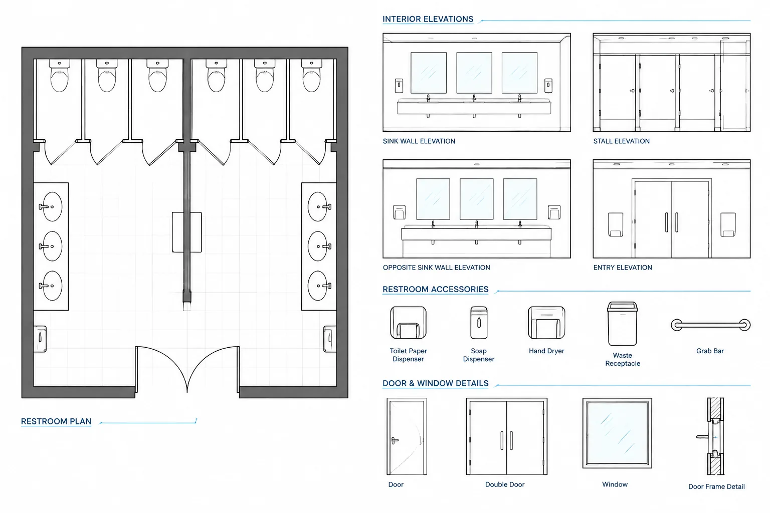
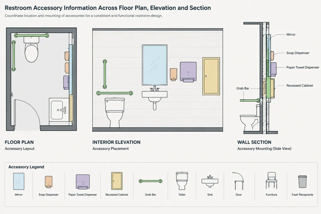
No single drawing view communicates every accessory condition effectively. A plan shows horizontal relationships, while an elevation explains vertical placement and alignment. Details can clarify recesses, backing, edges, and interfaces that would clutter the general drawings.
| Drawing view | Best use | Common coordination questions |
|---|---|---|
| Floor plan or enlarged plan | Location, projection, door conflicts, fixture relationships, and circulation | Does the accessory interfere with a door swing, partition, fixture, or required clear floor area? |
| Interior elevation | Mounting position, alignment, finish relationship, and vertical clearances | Is the item centered, aligned, reachable, and clear of controls or adjacent accessories? |
| Wall section or detail | Recess depth, backing, substrate, trim, and wall assembly interface | Does the wall have enough depth, and has required support been coordinated? |
| Accessory schedule | Identification, description, responsibility, mounting type, and remarks | Does every tag point to one unambiguous item? |
| Reflected ceiling plan | Only items that interact with ceiling-mounted elements or overhead coordination | Is there a conflict with lighting, diffusers, sensors, or ceiling features? |
Use the plan to establish the accessory’s general position, then use elevations to resolve mounting and alignment. Do not repeat every dimension in every view. Redundant dimensions can become contradictory when one view is revised and another is missed.
Build Plan and Elevation Blocks for Different Purposes
A useful accessory library should include graphic representations appropriate to the view. A plan symbol may emphasize projection from the wall and required operating space. An elevation block may show the visible outline, centerline, mounting reference, and tag location.
Keep product-specific detail out of generic planning blocks unless the project has selected and verified that exact product. A simplified block is often more durable during design because it communicates spatial needs without implying an unconfirmed model, finish, or installation method.
Recommended block characteristics
- Use a logical insertion point, such as the wall centerline, mounting center, or a clearly defined corner.
- Draw geometry at actual model size rather than compensating for plotted sheet scale.
- Keep linework simple enough to remain readable in enlarged plans and elevations.
- Place geometry, tags, and optional clearance graphics on appropriately managed layers.
- Use consistent orientation so mirrored or rotated blocks do not produce reversed text.
- Include attributes only when they support a controlled tagging or data workflow.
If an accessory block includes a clearance or operating-space outline, place that outline on a dedicated coordination layer. It can remain visible during layout reviews and be turned off for final plotting if the drawing set communicates the requirement elsewhere.
Lay Out Accessories in a Deliberate Sequence
Begin with fixed architectural and plumbing elements rather than placing accessories into an empty room. Confirm the partition faces, door frames, plumbing fixtures, countertops, casework, and major wall finishes first. Then add accessory zones in an order that exposes conflicts early.
- Reference the current architectural base. Verify that the enlarged restroom plan, overall plan, and interior elevations share the same wall and opening geometry.
- Place fixture-related accessories. Locate mirrors, dispensers, grab bars, and other components whose positions depend on plumbing fixtures.
- Add general-use components. Place dryers, towel dispensers, waste units, hooks, shelves, and changing stations according to the room program.
- Check doors and circulation. Review door swings, approach areas, projections, and points where users may stand while operating an accessory.
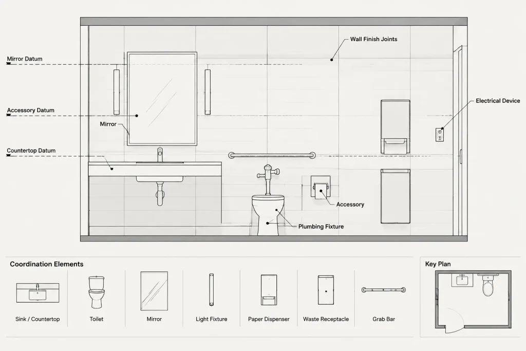
- Develop interior elevations. Resolve vertical relationships, alignments, finish joints, controls, outlets, and wall-mounted equipment.
- Identify recessed conditions. Confirm that the wall assembly can accommodate each recessed or semi-recessed unit.
- Add tags and schedule entries. Tag only after the layout has a stable accessory list, but before coordination reviews begin.
Coordinate Wall Support and Recessed Units
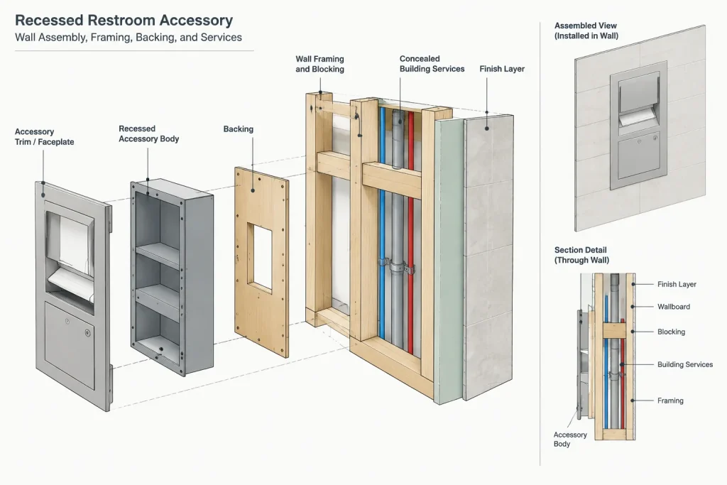
Wall-mounted accessories can require support that is not visible in the finished room. The architectural drawings should identify where backing, framing coordination, or another attachment strategy must be resolved. The exact solution should follow the selected component, wall construction, structural requirements, and project specifications.
Recessed accessories need additional scrutiny. A generic wall outline does not prove that sufficient cavity depth is available. Check for studs, plumbing, electrical work, fire-rated assemblies, acoustic requirements, and walls shared with other rooms. Where a recessed unit cannot fit, the design team may need to change the wall construction, select a different mounting type, or relocate the item.
Avoid drawing a recessed cabinet as though it simply cuts through every wall component. Use a section or enlarged detail to show the intended interface, and have the responsible disciplines verify penetrations and assembly continuity.
Coordinate Accessories with Finishes and Building Services
Interior elevations are the primary coordination view for accessories on finished walls. Compare accessory outlines with tile joints, wall panels, mirrors, backsplashes, countertops, electrical devices, plumbing controls, and signage. An installation can be technically possible yet look poorly resolved when components nearly align without sharing a clear organizing line.
Use reference lines or construction geometry to test common centers, edges, and datum relationships. Remove or place these aids on nonplotting layers after the elevation is resolved.
Electrical coordination is especially important for powered accessories. The architectural drawing should identify the intended item and position, while the electrical information should be checked for compatible power and control locations. Do not infer electrical requirements from a generic CAD block. Verify them against the selected equipment data and the project’s discipline drawings.
Create a Schedule That Supports Drawing Coordination
An accessory schedule should help the team identify what each tag means and who is responsible for it. Useful fields may include the tag, generic description, mounting type, room applicability, furnishing responsibility, installation responsibility, and coordination remarks.
Keep unverified product data out of the schedule. If a manufacturer or model has not been approved for project use, describe the item generically or clearly mark the selection status according to the project’s document practices. Dimensions, rough openings, power needs, and attachment information should come from verified product information rather than a downloaded block.
When an accessory occurs in several rooms, decide whether the schedule describes a typical requirement or records individual locations. Whichever method is selected, make exceptions visible. A single room with a different accessory should not be hidden behind a broad typical note.
Use Tags Without Obscuring the Plan
Place tags where leaders can point clearly to the intended object. In crowded restrooms, organize tags outside the room or along a consistent annotation band rather than scattering them between fixtures. Avoid crossing leaders and do not let a tag appear to point to two adjacent accessories.
For combination units, determine whether the assembly receives one tag or whether its components are identified separately. The decision should match the schedule structure. Tagging one physical unit as several unrelated objects can create quantity and procurement confusion.
Quality-Control Checks Before Issue
- Compare the overall plan, enlarged plan, and interior elevations for missing or duplicated accessories.
- Confirm that every tag has one corresponding schedule or legend entry.
- Check door swings and wall projections at each accessory location.
- Review fixture clearances and accessible layouts against the applicable project requirements.
- Verify that recessed units are compatible with the coordinated wall assembly.
- Check wall-mounted items for backing or attachment coordination.
- Compare powered accessories with electrical drawings and verified equipment information.
- Confirm that finish joints and accessory edges are intentionally coordinated.
- Look for mirrored blocks with reversed text or incorrect operating orientation.
- Plot the sheet and inspect whether tags, outlines, and leaders remain legible at final output size.
Keep the CAD File Useful Through Design Changes
Restroom layouts often change as fixtures, wall types, products, and finish concepts are refined. Keep accessory objects on dedicated layers, use stable tags, and avoid exploding blocks merely to make quick graphic edits. When product selections change, update the schedule and the affected plan and elevation blocks as one coordinated task.
The strongest workflow separates generic design intent from verified product information. Generic blocks support early layout, while selected equipment data informs final recesses, power locations, attachment details, and visible dimensions. That distinction helps prevent a convenient library symbol from being mistaken for a construction-ready product representation.
Well-coordinated restroom accessory drawings are concise but not vague. They show enough information to locate, identify, and integrate each item while directing detailed product and installation requirements to the appropriate schedule, detail, specification, or verified submittal.
Establish an Information Hierarchy
Before developing the drawings, decide where the controlling information for each accessory will reside. The plan may control horizontal location, the interior elevation may control visible alignment, and the schedule may control identity and responsibility. A detail can then explain a condition that cannot be communicated clearly in the general views.
This hierarchy reduces unnecessary duplication. If the same mounting or product information appears independently in several locations, revisions can leave conflicting instructions. Use cross-references, tags, and disciplined annotation so each drawing contributes a specific part of the coordination record.
Resolve Conflicting Information Deliberately
When plans, elevations, schedules, specifications, or equipment information disagree, do not adjust a block merely to make the drawing look correct. Identify which information has been verified, record the discrepancy, and coordinate the resolution with the responsible project team member.
A resolved change should be carried through every affected view. Moving an accessory in plan may also affect an elevation, finish layout, power location, backing requirement, tag leader, or schedule remark. Treat these related edits as one coordination task rather than separate drafting corrections.
Separate Design Graphics from Installation Data
Generic CAD blocks are useful for testing location, projection, orientation, and visual organization. They should not be treated as proof of a selected product’s recess, connection, support, or operating requirements. Product-dependent information belongs in verified project documentation after the selection has been reviewed.
This separation also makes the CAD library more reusable. A clear generic symbol can support early planning, while project-specific notes, attributes, and details can be added without turning the master block into an unreliable collection of assumptions.
Prepare a Clear Coordination Handoff
Before issuing drawings for review, make unresolved accessory conditions easy to find. Use the project’s established markup or tracking method to identify pending selections, questionable wall cavities, missing support information, service coordination, and responsibility questions.
A useful handoff distinguishes confirmed design intent from items awaiting verification. That distinction helps architects, consultants, contractors, and reviewers focus on genuine coordination decisions instead of assuming that every visible CAD outline represents final installation information.
Frequently Asked Questions
Should restroom accessories appear in both plan and elevation?
Show an accessory in each view needed to communicate its condition clearly. Plans are generally useful for horizontal location and projection, while elevations explain mounting relationships and visual alignment. Avoid repeating information that has a single controlling location elsewhere in the drawing set.
Can a downloaded CAD block be used as verified product information?
No. A block can support layout and graphic communication, but its geometry does not confirm the selected product, installation method, wall recess, attachment, or service requirements. Compare project documentation with verified equipment information before developing construction details.
How should recessed accessories be checked?
Review the full wall condition rather than only the visible face. Coordinate the intended recess with framing, substrates, finishes, concealed services, adjacent rooms, and any assembly requirements identified by the project team. Use a section or detail when the interface is not clear in plan or elevation.
What is the best way to prevent accessory tags from becoming confusing?
Use stable identifiers, consistent leader placement, and an unambiguous schedule or legend. Keep tags clear of fixtures and dense linework, and verify that each leader points to only the intended accessory or coordinated assembly.
When should product-specific accessory blocks replace generic blocks?
Replace or update generic geometry only after the project team has verified the selected equipment information. Any change should then be coordinated across plans, elevations, schedules, details, finishes, supports, and applicable service drawings.