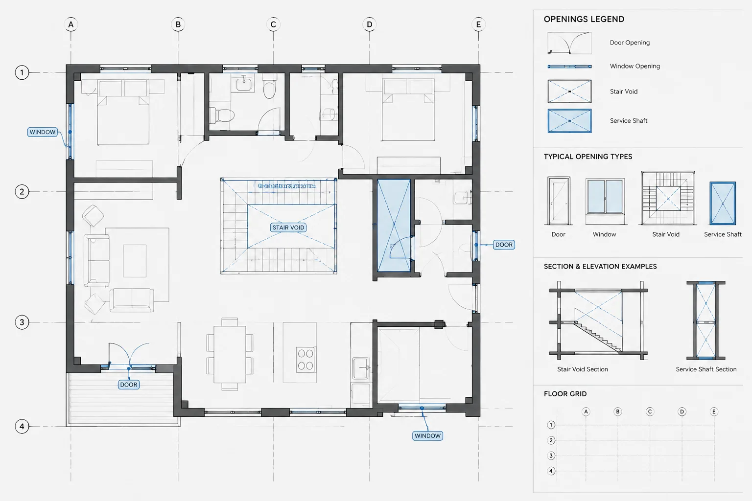
Drafting floor openings requires more than outlining a gap in a slab. The CAD geometry must distinguish the physical opening from nearby guards, curbs, frames, enclosures, equipment clearances, and elements visible above or below the plan cut.
This guide explains a practical workflow for classifying, drawing, annotating, and reviewing floor openings in architectural CAD. It also addresses coordination between floor plans, sections, details, consultant backgrounds, and vertically aligned building systems.
Floor openings can be easy to draw but difficult to coordinate. A simple rectangle in plan may represent a stair void, an atrium edge, a mechanical shaft, a floor hatch, or a framed opening for building services. Each condition affects multiple drawings and may involve architectural, structural, mechanical, electrical, plumbing, fire-protection, and specialty consultants.
A reliable workflow must do more than show the opening boundary. It should communicate what is removed, where the edge is located, which elements continue through the opening, and where the condition is explained elsewhere. The following process focuses on clear architectural CAD geometry and disciplined coordination rather than project-specific engineering or code decisions.
Start by Classifying the Opening
Before drafting, determine what the opening represents. Different opening types require different plan graphics, references, and coordination checks.
- Large occupied-space openings: atriums, communicating stairs, and double-height spaces.
- Circulation openings: stair, ladder, and access openings connecting floor levels.
- Building-service openings: mechanical, plumbing, electrical, and combined utility shafts.
- Equipment-related openings: pits, hatches, lifts, conveyors, and equipment penetrations.
- Localized penetrations: sleeves, ducts, pipes, conduits, and similar service routes.
- Temporary or reserved openings: areas held for future equipment or later construction.
This classification helps determine whether the condition belongs in the primary architectural model, a consultant reference, a schedule, a detail, or a combination of these locations. It also prevents a common mistake: treating every penetration as though it needs the same graphic emphasis.
Establish a Clear Source of Geometry
The opening boundary should have one identifiable source. On a small project, that source may be the architectural floor plan. On a consultant-heavy project, a structural or MEP drawing may define part of the requirement. Regardless of who initiates it, avoid maintaining several unrelated copies of the same boundary.
When a repeated opening must appear on several architectural plans, consider using a controlled block or referenced background rather than redrawing it independently. If the geometry is copied between files, assign responsibility for updating all copies when the opening changes.
Do not assume a consultant outline is ready for construction merely because it appears precise. Confirm whether it represents a required clear opening, a rough opening, a sleeve, an equipment clearance area, or only a preliminary routing zone.
Build the Opening Boundary as Clean CAD Geometry
Create a closed, easy-to-select boundary for the actual floor opening. A closed polyline is often more manageable than separate line segments because it can be checked, measured, hatched, offset, and revised as one object.
Keep these geometry practices in mind:
- Snap the boundary to known grids, walls, columns, or other controlled references where appropriate.
- Avoid nearly closed corners, duplicate lines, and short overlapping segments.
- Do not use a hatch boundary as the only definition of the opening.
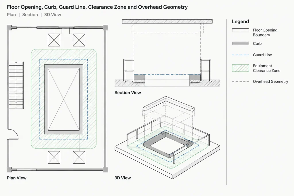
- Separate the true opening edge from clearance zones, curbs, guards, frames, and equipment extents.
- Use object properties consistently rather than applying unexplained color or linetype overrides.
If the opening changes shape between levels, draw and label each level condition separately. A shaft enclosure may align vertically while the slab openings inside it vary because of structure, offsets, or service routing.
Assign Layers by Meaning, Not Just Appearance
Floor-opening graphics should remain distinguishable from walls, structural framing, equipment, and annotation. The exact layer names depend on the project template, but the layer structure should identify purpose.
| CAD content | Recommended distinction | Reason |
|---|---|---|
| Opening edge | Primary opening or slab-edge layer | Allows the actual cut boundary to be isolated and checked |
| Elements below | Below-view or hidden layer | Clarifies lower-level context without competing with the current plan |
| Overhead edges | Overhead layer | Separates geometry above the plan cut from the floor opening |
| Guard, curb, or frame | Element-specific layer | Prevents protective or finish components from being mistaken for the opening |
| Opening tags and notes | Annotation layer | Supports viewport control and consistent plotted text |
| Coordination zones | Nonplot or coordination layer | Keeps working geometry out of issued sheets |
Avoid combining the opening edge and its surrounding guard or curb into a single graphic object. They may look related in plan, but they represent different physical components and often change for different reasons.
Choose Plan Graphics That Explain the Vertical Condition
The plan must make it clear that the floor does not continue through the opening. The appropriate combination of lines, poche, break symbols, and notes depends on the drawing scale and office convention.
Show what is visible at the current level
Draw the cut or visible slab edge with enough emphasis to read as a boundary. Show nearby walls, rails, curbs, shaft enclosures, or trim according to their relationship with the plan cut plane.
Control information above and below
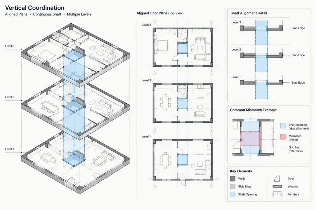
Geometry below the opening can help explain stairs, landings, equipment, or the room beneath, but it should be visually subordinate. Overhead edges should also be distinct. Do not use the same line treatment for both unless another graphic device makes their locations unmistakable.
Avoid masking unresolved geometry
A wipeout or background mask can improve legibility, but it should not hide conflicts that still need coordination. First clean the boundary and establish draw order; then use masking only where it supports the intended representation.
Dimension to Stable References
Locate openings from references that are expected to remain coordinated, such as structural grids, wall faces, column lines, or established control lines. Avoid relying only on chained dimensions from movable partitions or finish elements unless those references intentionally control the opening.
Dimensions should answer the necessary construction questions without creating redundant strings. Depending on the condition, drawings may need to communicate:
- Opening width and length.
- Offset from a grid, wall, column, or shaft face.
- Relationship to an adjacent stair, curb, or equipment footprint.
- Alignment with an opening on another floor.
- Irregular corners, notches, or changes in direction.
Opening dimensions are project-specific. Verify them against the responsible discipline, selected equipment, assembly details, and applicable project requirements rather than adopting values from a generic CAD block.
Use Tags and References for Complex Conditions
A plan note can identify the opening, but it should not carry every construction instruction. Larger or more complicated conditions usually benefit from a section, enlarged plan, or detail reference.
A useful opening identifier may coordinate with an opening list or project issue log. If identifiers are used, keep them unique and consistent across architectural and consultant files. Avoid changing an identifier simply because the boundary was adjusted; first determine whether the revised condition is still the same coordinated opening.
Reference a section where vertical relationships matter, including slab edges, curbs, frames, enclosure walls, waterproofing transitions, guards, and nearby ceilings. The reference should point to a view that actually resolves the question rather than merely repeating the plan.
Coordinate Across Floors and Disciplines
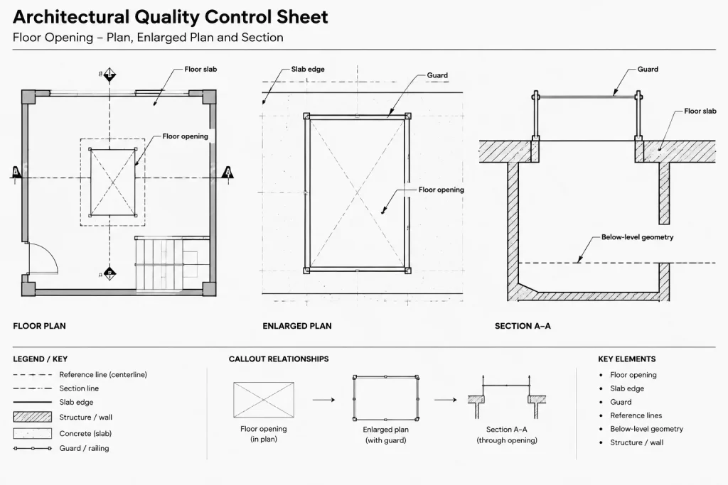
Review floor openings as vertical elements, not isolated plan symbols. Stack the relevant floor plans at a shared coordinate position and compare the boundaries. This quickly reveals shifted shafts, framing conflicts, discontinuous walls, and penetrations that do not align with service routes.
Compare the architectural plan with:
- Structural slab edges, beams, joists, and columns.
- Mechanical ducts, shafts, equipment, and access requirements.
- Plumbing risers, drains, and grouped piping routes.
- Electrical and communications pathways.
- Ceiling plans, soffits, and access panels.
- Stair plans, sections, railings, and landing edges.
- Roof plans where a shaft or service route continues upward.
Architectural drawings should not independently determine structural framing modifications or final service penetration requirements. Flag discrepancies and obtain confirmation from the responsible project team member.
Run a Focused Quality-Control Review
Before issuing drawings, isolate the opening-related layers and inspect each condition in context. Then review the plotted sheet, because line hierarchy and masking problems may not be obvious in model space.
- Is every opening represented by clean, closed geometry?
- Can the actual floor edge be distinguished from a curb, guard, frame, or clearance zone?
- Do corresponding plans, sections, and details show the same shape and location?
- Are opening dimensions tied to stable references?
- Do shaft and stair openings align correctly between levels?
- Are consultant backgrounds current and positioned at the correct project origin?
- Are abandoned alternatives removed or placed on clearly nonplot coordination layers?
- Do tags and detail references lead to the intended views?
- Does the plotted plan clearly distinguish current-level, overhead, and below-level geometry?
Treat Openings as Coordinated Building Elements
A dependable floor-opening workflow combines clean CAD geometry, controlled layers, stable dimensions, vertical comparison, and clear view references. The goal is not to make the opening symbol more elaborate. It is to ensure that every drawing describes the same physical condition.
When opening boundaries are maintained as coordinated elements instead of incidental linework, changes become easier to track and conflicts become easier to find. That discipline is especially valuable for stairs, shafts, equipment openings, and service penetrations that affect several floors and drawing disciplines.
Practical Handoff and Revision Strategy
A coordinated opening should remain understandable when the drawing passes from one team member or discipline to another. The boundary, controlling references, opening identifier, related views, and current coordination status should be easy to recognize without relying on personal knowledge of the file.
When an opening changes, review the change as a building condition rather than as an isolated CAD edit. A revised boundary may affect dimensions, slab-edge graphics, framing coordination, shaft walls, guards, stairs, equipment access, ceiling information, and referenced details. Update dependent views together or clearly record which items remain unresolved.
Separate confirmed geometry from coordination allowances
A required opening and a working clearance zone do not communicate the same thing. Keep preliminary routing areas, equipment allowances, and consultant coordination zones visually separate from the confirmed floor edge. This reduces the risk that temporary working geometry will be interpreted as an issued construction boundary.
Review additions, shifts, and removals
Quality control should include deleted and relocated openings, not only new ones. Removing an opening from a plan does not automatically remove related annotations, lower-level graphics, section references, consultant penetrations, or details. Search the drawing set for the opening identifier and inspect vertically adjacent plans before treating the revision as complete.
Preserve decision context
Where the project workflow allows it, record which discipline controls the opening requirement and whether the geometry is preliminary or confirmed. The issued drawings should remain clear and uncluttered, while internal coordination records can preserve the information needed to evaluate later changes.
Frequently Asked Questions
What is the best CAD object for a floor-opening boundary?
A clean, closed boundary is generally easier to select, check, revise, and compare than disconnected line segments. The object should represent the actual floor edge rather than a clearance area, frame, curb, or enclosure.
Should floor openings be drawn on architectural or consultant files?
The responsible source depends on the project workflow and the type of opening. Regardless of file ownership, the team should identify one controlling boundary and avoid maintaining unrelated versions that can drift out of alignment.
How should an opening be shown when its shape changes between floors?
Represent and label the condition separately on each affected level. Compare the plans at a common coordinate position, and use sections or details to explain offsets and other vertical relationships that are unclear in plan.
Are a shaft outline and a slab opening the same thing?
Not necessarily. A shaft outline may describe enclosure walls or a reserved service zone, while the slab opening describes the actual removed floor area. Keeping these elements separate makes coordination and revision checks more reliable.
When does a floor opening need a section or detail reference?
Add a reference when the plan cannot clearly explain the vertical condition or the relationship among slab edges, curbs, frames, enclosure walls, guards, ceilings, equipment, and adjacent construction.
What should be checked after a floor opening moves?
Review controlling dimensions, stacked floor plans, structural framing, service routes, nearby walls, stairs, ceilings, tags, and referenced views. Also look for abandoned linework or annotations at the previous location.