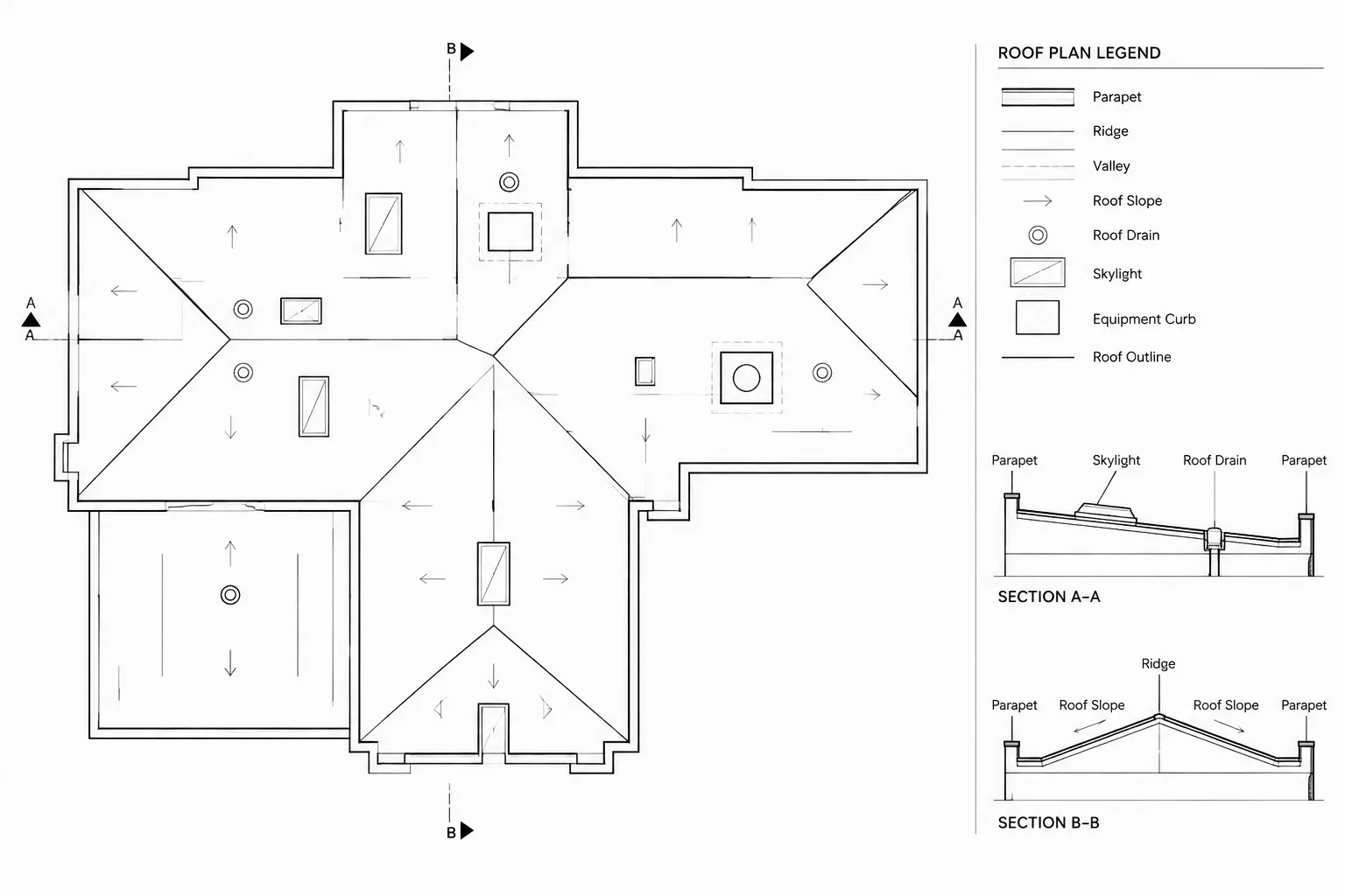
Drafting an architectural roof plan in CAD requires more than tracing a perimeter. The drawing must explain roof planes, transitions, drainage intent, access, openings, and rooftop elements while remaining coordinated with the building below.
This guide presents a practical workflow for assembling the plan from controlled references, organizing linework, and checking relationships across architectural and consultant documents. It also highlights where project-specific engineering, product, and code information must be verified rather than assumed.
An architectural roof plan communicates more than the outline of a building. It explains how roof surfaces relate, where they rise and fall, how edges are formed, and where openings, equipment, drainage components, and adjacent construction occur. A clear roof plan also provides a coordination base for structural, mechanical, plumbing, and envelope information.
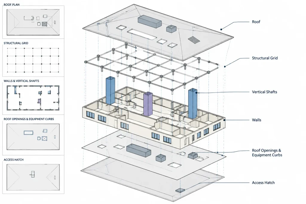
The drafting process should begin with dependable building geometry rather than an isolated roof sketch. Walls, grids, structural supports, vertical shafts, and exterior projections can all affect the roof. The following workflow focuses on organizing that information in CAD while keeping the drawing readable and suitable for ongoing coordination.
Establish the purpose of the roof plan
Before drawing, determine what the roof plan must communicate at its intended sheet scale. A general architectural roof plan may show overall roof geometry, edges, slopes, openings, drainage intent, access points, and major rooftop elements. Enlarged plans or details can carry conditions that would clutter the overall view.
Confirm whether the drawing represents new construction, existing conditions, demolition, or a combination. These conditions should be graphically distinct. Also identify which consultant drawings will provide structural framing, roof drainage engineering, equipment data, and penetration requirements. The architectural roof plan should coordinate those sources without presenting unverified consultant information as final.
Build the plan from coordinated references
Use the current architectural floor plan as the primary geometric reference, preferably through a controlled external reference rather than copied linework. Add structural and consultant backgrounds when they are available and appropriate for coordination. Align every reference using the project origin, agreed coordinates, or another documented control point.
Useful background information commonly includes:
- Exterior walls, parapets, and major interior bearing lines
- Column grids and structural supports
- Stairs, elevators, shafts, and roof access locations
- Courtyards, canopies, lower roofs, and adjacent building volumes
- Mechanical equipment and required service areas
- Plumbing drainage locations and overflow provisions
- Property or zoning constraints when they affect roof projections
Fade or screen reference information so that proposed roof geometry remains visually dominant. Avoid redrawing background objects unless they must become part of the architectural document. Duplicate geometry can drift out of alignment when revisions occur.
Draft the primary roof geometry
Start with controlling edges
Draw the main roof perimeter from verified wall, parapet, fascia, or overhang locations. Do not assume the roof edge matches the exterior wall face. Different portions of a building may use parapets, projecting eaves, gutters, canopies, or concealed edges.
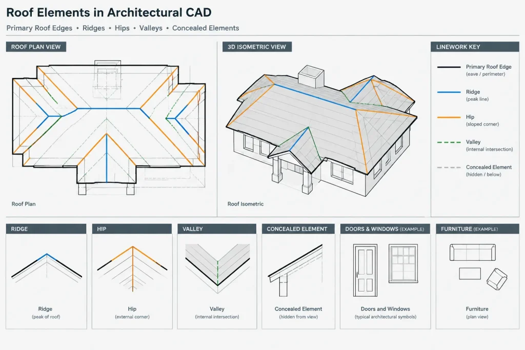
Organize roof edges by meaning rather than placing every line on one generic layer. Perimeters, ridges, valleys, hips, parapets, overhead elements, and concealed lines may need different lineweights or linetypes. A consistent layer structure makes later graphic adjustments easier.
Resolve intersecting roof surfaces
For sloped roofs, establish the major roof planes before adding small dormers, crickets, or secondary projections. Determine which edges are high, low, or level, and trace how water would travel across each surface. Intersections should form a coherent network of ridges, hips, and valleys.
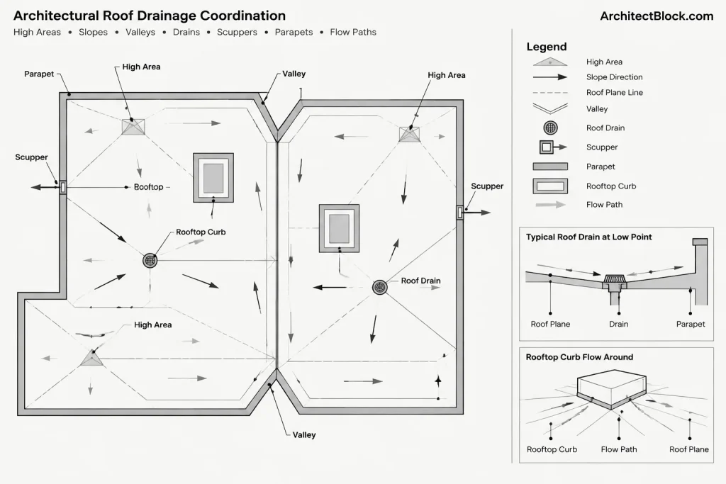
For low-slope roofs, identify parapet limits, high points, low points, sumps, drains, scuppers, and changes in roof elevation. Avoid depicting the surface as a featureless rectangle. Even when detailed drainage design is provided by others, the architectural drawing should clearly show the coordinated intent and direct the reader to the responsible documents where necessary.
Show roofs at different elevations clearly
Separate upper roofs, lower roofs, canopies, and adjacent roof areas with clear edge graphics and elevation references. Use line hierarchy, break lines, or view separation so readers can understand which surfaces overlap. Where an upper plan includes a lower roof beyond the building edge, show only the information needed to explain the relationship.
Represent slopes without ambiguity
Slope arrows should point consistently according to the office drafting convention, and their meaning should be defined if it is not self-evident. Pair arrows with verified slope information, spot elevations, or high and low point labels as appropriate to the project. Do not infer slopes from appearance alone.
A useful slope graphic should answer three questions:
- Which roof surface does the notation apply to?
- In which direction does that surface fall?
- Where does the water or surface transition go?
Place notation within the applicable roof area and avoid arrows that cross ridges, openings, or unrelated surfaces. When a complex area cannot be explained cleanly on the overall plan, create an enlarged roof or drainage plan.
Add roof openings, access, and rooftop elements
After the main surfaces are stable, add coordinated penetrations and mounted components. These may include roof hatches, skylights, smoke vents, ducts, exhaust outlets, plumbing vents, equipment curbs, screens, and fall-protection components. The exact scope varies by project.
Use blocks for repeated symbols only when the blocks have dependable insertion points, orientation, layer behavior, and attributes. A symbol should not imply a verified product size or clearance unless it has been checked against current project information.
For each significant rooftop item, coordinate:
- The opening or curb footprint
- The supporting structure below
- Nearby roof edges and changes in elevation
- Drainage paths around the obstruction
- Access and service space shown by the responsible discipline
- Related plan, section, elevation, schedule, or detail references
Large equipment should not be placed solely from a generic CAD block. Use current consultant and manufacturer information, and verify the relationship between the equipment outline, curb, connection points, screens, and structural support.
Coordinate roof drainage graphically
Trace drainage from high points to discharge locations. Look for roof shapes that could trap water behind curbs, walls, or changes in plane. Secondary features such as crickets and saddles should be coordinated where the design requires them, but their geometry should not be improvised without design input.
Roof drains, gutters, downspouts, scuppers, and overflow paths should use distinct, consistently labeled symbols. Their final design, quantity, sizing, and code compliance must be verified by the responsible professionals. The architectural plan can document location and coordination intent without claiming engineering authority.
Use a readable graphic hierarchy
| Drawing information | Typical graphic treatment | Coordination purpose |
|---|---|---|
| Primary roof edges and parapets | Strong, continuous linework | Defines the roof boundary |
| Ridges, hips, and valleys | Clear secondary linework | Explains changes between roof planes |
| Items below or concealed | Controlled dashed or screened linework | Provides context without competing with roof geometry |
| Drainage and slope symbols | Consistent symbols and annotations | Communicates direction and collection points |
| Consultant background | Screened or subdued display | Supports coordination while preserving authorship |
| Tags and detail references | Uniform annotation style | Connects the plan to related drawings |
Test the plan at its intended plotted scale. Linework that looks separated in model space may merge on the sheet, while dense labels may obscure critical intersections. Use a plot preview or review PDF rather than judging the drawing only on screen.
Add references and annotation deliberately
Label roof levels, major roof areas, access points, drainage elements, and significant transitions. Add section, elevation, and detail callouts where they explain edge conditions, curbs, parapets, openings, or changes in construction. Keep notes close enough to their subjects to prevent mistaken associations.
Avoid repeating the same requirement in several unrelated notes. Repetition creates opportunities for conflicting edits. Use a general note for genuinely common conditions and local notes for exceptions. If a requirement originates in a consultant drawing or specification, coordinate the reference rather than paraphrasing technical criteria inaccurately.
Perform a final roof-plan coordination review
Review the drawing systematically before issue. A practical checklist includes:
- Compare the roof perimeter with exterior walls, parapets, and building sections.
- Check that ridges, hips, valleys, and slope arrows describe possible roof surfaces.
- Trace drainage paths and identify apparent trapped areas or interrupted flows.
- Compare openings with shafts, rooms, ceilings, and structural framing below.
- Confirm that rooftop equipment matches the latest consultant background.
- Verify that roof access connects logically to stairs, ladders, or hatches.
- Check alignment among roof plans, elevations, wall sections, and details.
- Confirm that tags, detail references, and sheet references point to current views.
- Freeze unnecessary background layers in the sheet viewport.
- Review the plotted PDF for lineweight, linetype, text, and symbol clarity.
A well-coordinated architectural roof plan is both a geometric drawing and an information map. By building it from controlled references, resolving roof surfaces before adding detail, and clearly separating architectural intent from consultant design, CAD users can produce a drawing that is easier to review, revise, and construct from. Final dimensions, drainage design, equipment requirements, structural support, and code-related conditions should always be verified for the specific project.
How to apply the workflow during production
Treat the roof plan as a live coordination drawing rather than a one-time drafting task. Establish dependable base geometry first, then add roof surfaces, drainage information, penetrations, equipment, and annotations in controlled stages. This sequence makes conflicts easier to identify and reduces the risk of adjusting secondary information around an incorrect roof outline.
Separate geometry from annotation
Keep roof edges, surface transitions, symbols, references, and notes logically organized. When geometry changes, this separation helps the drafter update the affected information without disturbing unrelated content. It also supports clearer viewport control and plotted output.
Review relationships, not just individual objects
A roof hatch may be drawn correctly but still conflict with a structural member or fail to align with an access route below. A drain symbol may be clear while the surrounding slope graphics suggest that water moves elsewhere. Coordination review should therefore follow each element through the related plans, sections, details, and consultant backgrounds.
Record unresolved coordination items
Do not conceal uncertainty with overly specific linework or notes. If equipment data, support conditions, drainage design, or penetration requirements remain unresolved, identify the issue through the project coordination process and update the drawing when verified information becomes available.
Common roof-plan drafting problems
- Copied background geometry: Detached copies can become outdated when the source plan changes.
- Unclear elevation relationships: Upper roofs, lower roofs, canopies, and concealed construction can appear to occupy the same plane.
- Ambiguous slope graphics: Arrows or labels may not clearly identify the applicable roof surface or destination of flow.
- Generic equipment blocks: Symbols can be mistaken for verified footprints, curbs, connections, or service areas.
- Overloaded plans: Excessive notes and background linework can hide important roof intersections and drainage elements.
- Disconnected references: Plan callouts may not agree with current sections, elevations, schedules, or details.
The final drawing should be checked at its intended sheet presentation and compared with the current project references. Architectural clarity does not replace professional verification of structural support, drainage performance, equipment requirements, envelope conditions, or code compliance.
Frequently asked questions
What should an architectural roof plan show?
It commonly communicates roof boundaries, roof planes, ridges, hips, valleys, parapets, elevation changes, slope direction, drainage components, openings, access points, major equipment, and references to related views. The exact content depends on the project and drawing scope.
Should the roof plan be drawn from the floor plan?
The current floor plan is usually an important geometric reference because walls, shafts, grids, and projections affect the roof. However, the roof edge should not automatically be assumed to match the exterior wall face. Parapets, eaves, gutters, canopies, and other conditions must be verified.
How should consultant backgrounds be used in CAD?
Use controlled references aligned to an agreed project coordinate or control point. Display consultant information with a subdued graphic treatment so it supports coordination without being confused with architectural authorship.
How can sloped and low-slope roofs be made easier to read?
Use a consistent hierarchy for boundaries, surface transitions, slope graphics, high and low points, and drainage destinations. Separate roofs at different elevations clearly, and use enlarged views when the overall plan becomes crowded.
Can generic CAD blocks be used for rooftop equipment?
Generic blocks may support early coordination, but they should not be treated as verified equipment, curb, opening, connection, or service-space information. Replace or revise them using current project data from the responsible sources.
Who verifies roof drainage and structural support?
The responsible project professionals must verify drainage design, structural support, equipment requirements, and code-related conditions. The architectural roof plan should coordinate and communicate verified intent without implying authority outside its scope.
What should be checked before issuing the roof plan?
Compare the roof plan with floor plans, consultant backgrounds, elevations, sections, details, and schedules. Review roof edges, transitions, drainage paths, penetrations, access, equipment, references, layer visibility, lineweights, linetypes, text, and symbols in the plotted output.