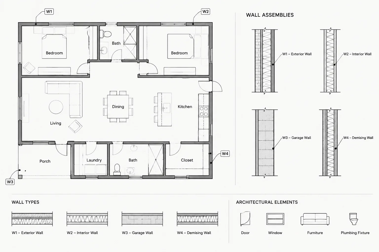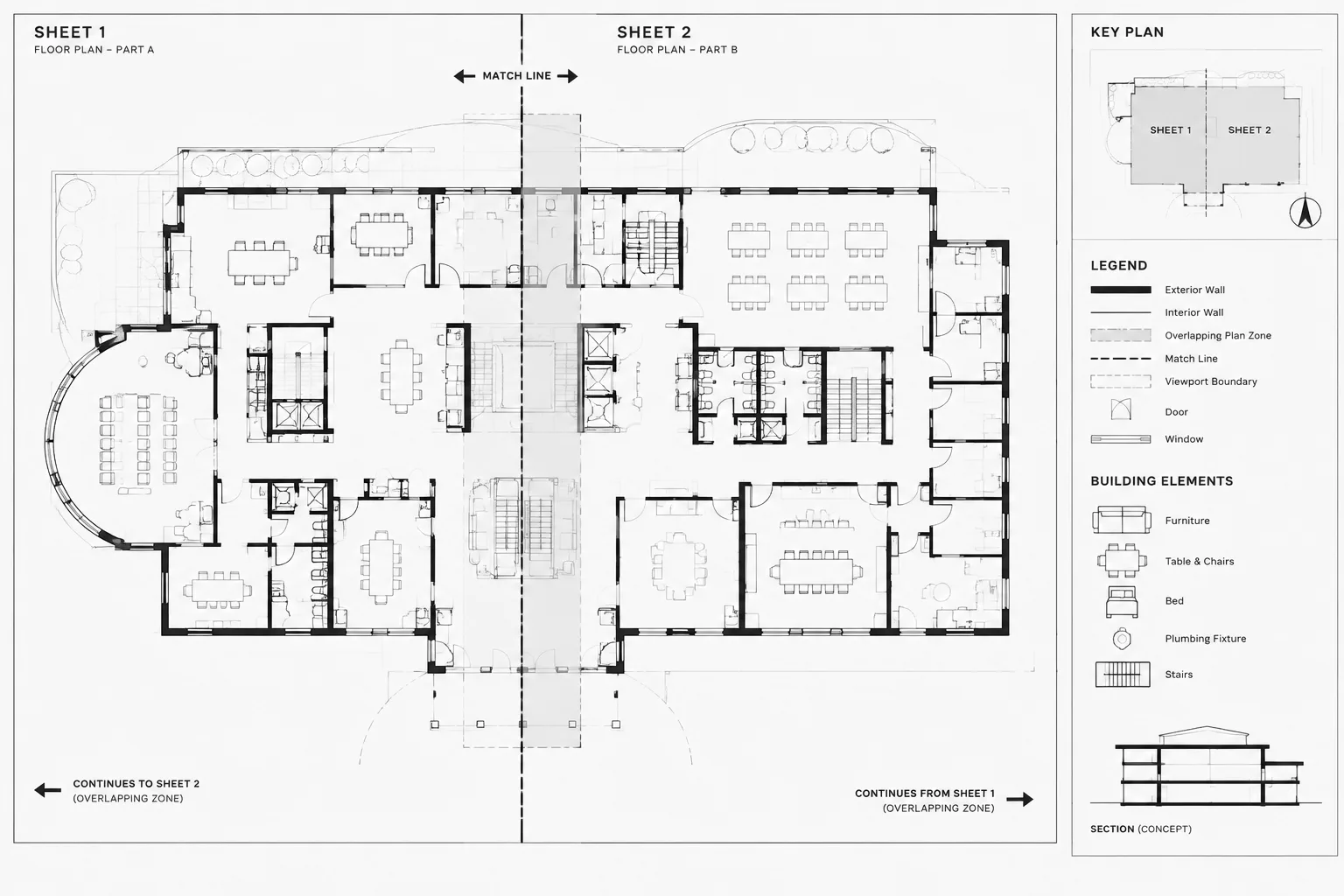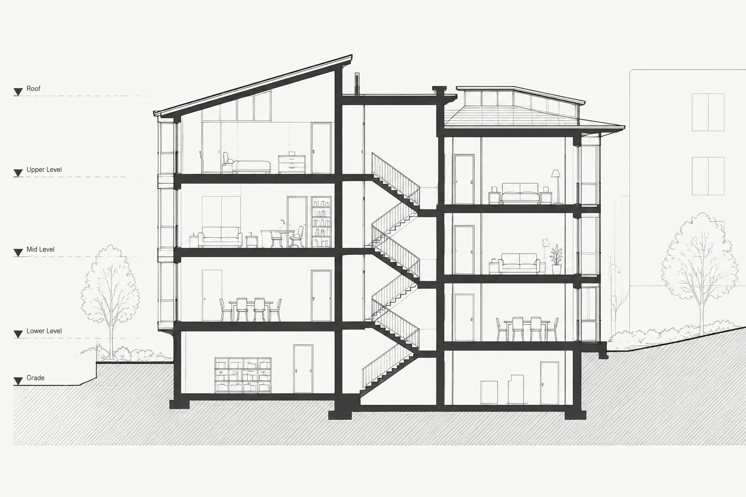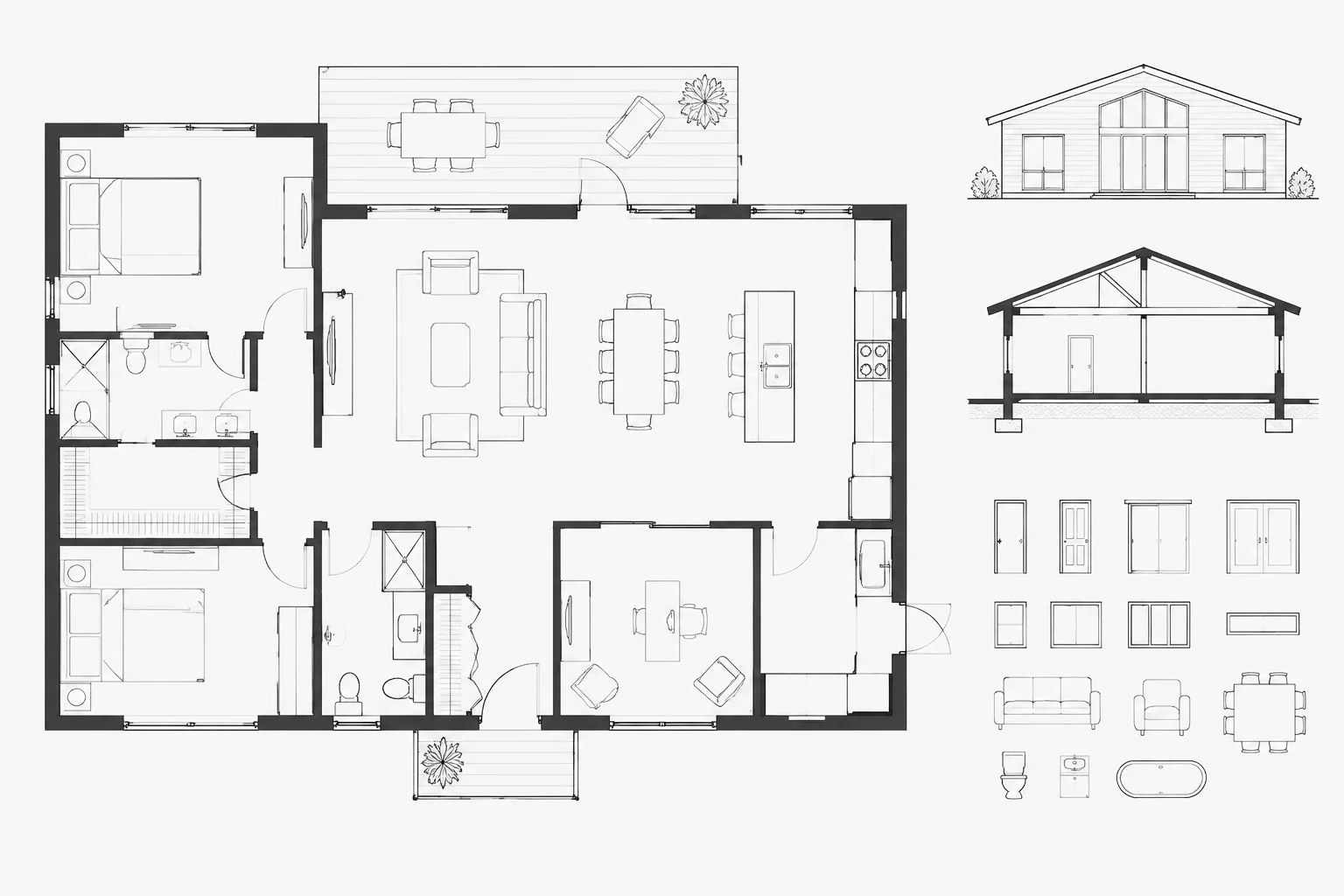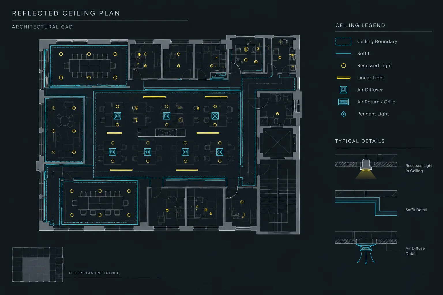
Drafting a reflected ceiling plan in CAD requires more than arranging symbols above each room. The drawing must preserve alignment with the architectural plan, distinguish design intent from consultant-owned information, and remain readable as backgrounds and ceiling systems change.
This guide presents a practical workflow for establishing ceiling zones, organizing layers, locating overhead components, coordinating referenced files, and checking the completed RCP against the rest of the architectural drawing set.
A reflected ceiling plan, commonly called an RCP, shows the design and coordination of elements at or near the ceiling plane. It may include ceiling boundaries, material changes, light fixtures, air devices, access panels, sprinklers, speakers, detectors, soffits, and other overhead components. Although the view is drawn as if the ceiling were reflected onto a horizontal plane, it must remain aligned with the architectural floor plan.
A useful RCP is more than a collection of ceiling symbols. It establishes a readable overhead layout, communicates design intent, and gives architectural and engineering teams a common background for coordination. The following workflow explains how to build that drawing in CAD without allowing duplicated geometry or consultant information to become unmanageable.
Understand What the Reflected Ceiling Plan Must Communicate
Before drafting, define the purpose and expected level of detail. A design-development RCP may emphasize ceiling forms, fixture relationships, and material zones. A construction drawing may require more complete identification, dimensions, references, and coordination with consultant drawings.
The architectural RCP commonly communicates:
- Ceiling extents and transitions between ceiling types
- Changes in ceiling elevation, including soffits and bulkheads
- Suspended grid orientation where relevant to the design
- Architecturally located light fixtures and decorative fixtures
- Access panels and other visually significant ceiling components
- Ceiling tags, notes, dimensions, and detail references
- Open-to-structure areas and exposed overhead conditions
Engineering elements may be visible for coordination, but ownership must remain clear. The architect should not silently replace verified electrical, mechanical, fire protection, or technology information with approximate architectural graphics.
Start with a Controlled Floor Plan Background
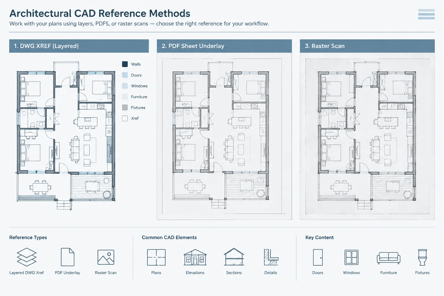
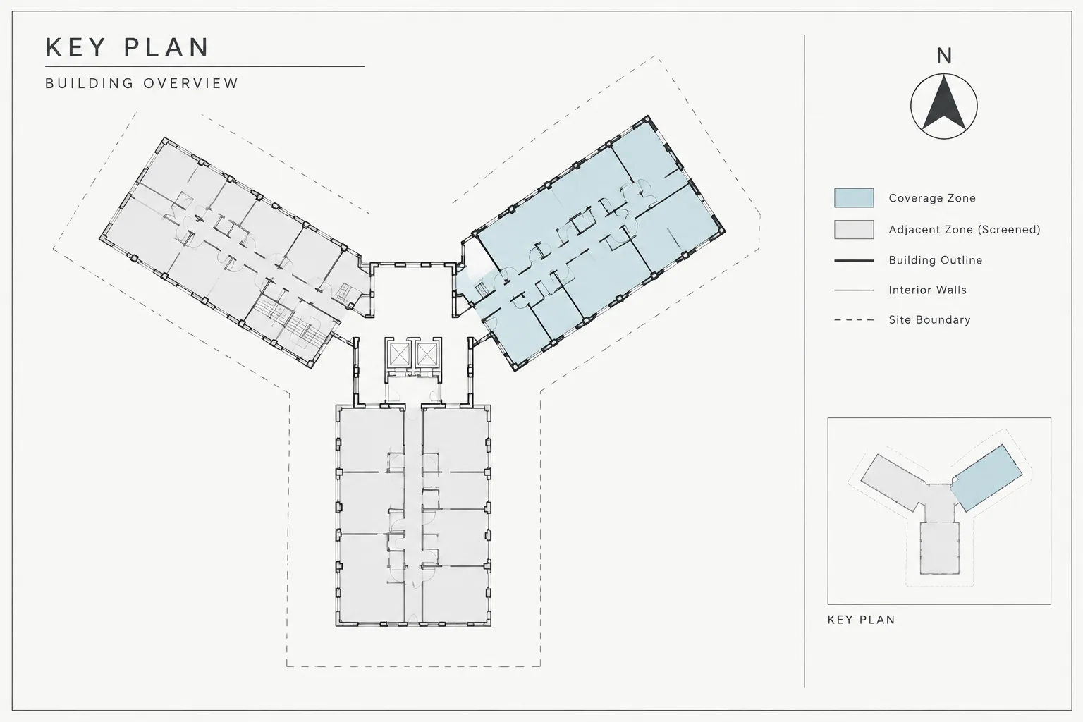
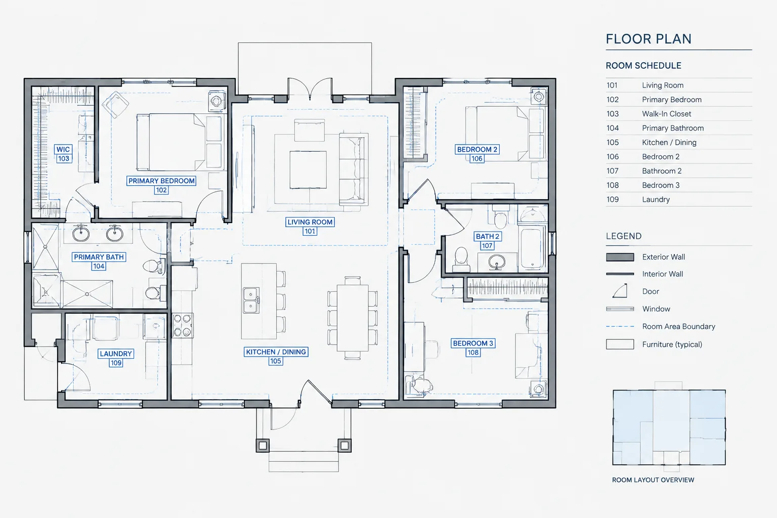
Use the current architectural floor plan as the positional reference. In a coordinated project, it is usually better to reference the plan than to copy walls, columns, doors, and room geometry into the RCP file. A reference-based workflow reduces the risk of ceiling information remaining aligned with an outdated plan.
Display only the background information needed to understand the ceiling. Walls, columns, room boundaries, stairs, major casework, and door openings may provide useful orientation. Dense furniture, finish patterns, equipment notes, and floor-plan dimensions often create unnecessary clutter.
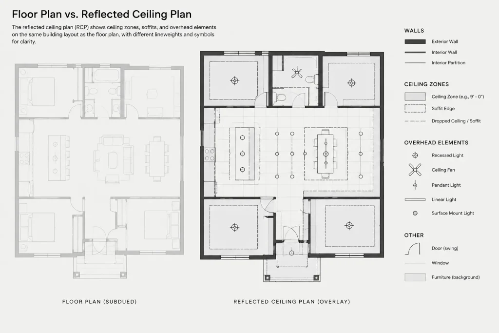
The floor plan background should be graphically subdued. Ceiling geometry and overhead components need to read more strongly than the plan information below. Apply this hierarchy through layers, colors, lineweights, screening, or viewport controls according to the office plotting system.
Establish Ceiling Boundaries Before Placing Components
Begin with the overall ceiling regions rather than individual lights or air devices. Trace the interior limits that actually control the ceiling, including wall faces, soffit edges, shafts, double-height spaces, and openings to levels below. Do not assume every room has one continuous ceiling condition.
Separate distinct ceiling zones using closed, clean boundaries where practical. Closed boundaries make hatch management, area review, and later revisions easier. They also help reveal small gaps or overlaps at wall intersections.
Identify the Main Ceiling Conditions
For each room or zone, determine whether the ceiling is continuous, suspended, sloped, exposed, or interrupted by architectural features. Show transitions deliberately. A simple line may be sufficient for a material change at the same elevation, while a soffit edge or vertical drop may require a different graphic convention and a supporting section or detail.
Do not rely on hatch patterns alone to explain ceiling construction. Patterns can become difficult to read when drawings are reduced, printed in grayscale, or viewed over consultant information. Combine graphic distinctions with ceiling tags, notes, or keyed references.
Organize RCP Information with Purpose-Built Layers
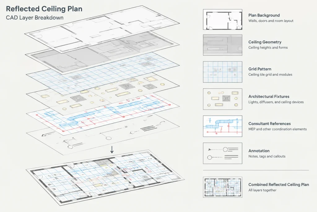
Ceiling drawings are easier to control when their content is divided by function. The exact layer names should follow the project template, but the structure should distinguish architectural geometry, symbols, annotation, references, and consultant information.
| Information group | Typical content | Coordination purpose |
|---|---|---|
| Ceiling geometry | Boundaries, soffits, transitions, grid lines, and openings | Defines the architectural ceiling layout |
| Ceiling annotation | Tags, notes, dimensions, elevations, and callouts | Explains conditions that geometry cannot communicate alone |
| Architectural fixtures | Decorative lights, ceiling-mounted accessories, and access panels | Controls elements selected or located by the architect |
| Plan background | Walls, columns, doors, and room references | Provides orientation without dominating the sheet |
| Consultant references | Lights, diffusers, sprinklers, detectors, and speakers | Supports multidisciplinary coordination |
Avoid placing all overhead symbols on one generic layer. When disciplines issue revised information, separated layers allow the project team to isolate changes and troubleshoot conflicts without hiding unrelated content.
Lay Out Repetitive Systems from Clear Control Lines
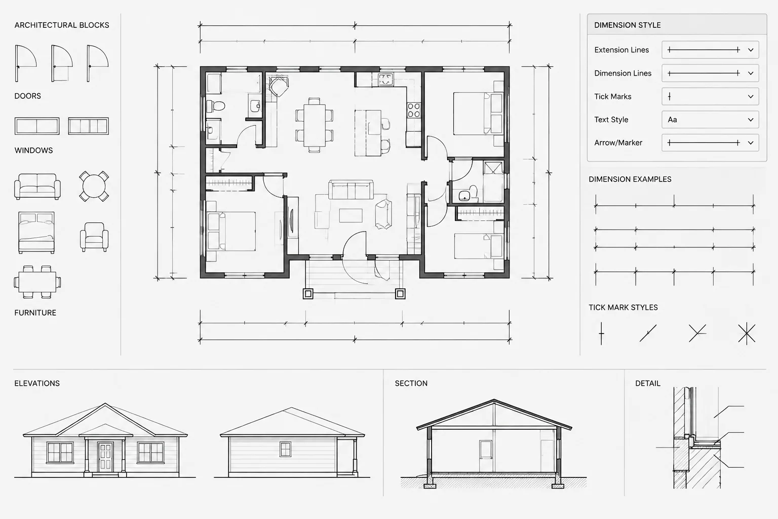
Suspended grids, linear ceilings, wood slats, baffles, and repeated fixtures require a recognizable layout logic. Establish reference axes from room geometry or a documented design feature. Examples include the room centerline, a corridor axis, a major opening, a millwork composition, or an important elevation alignment.
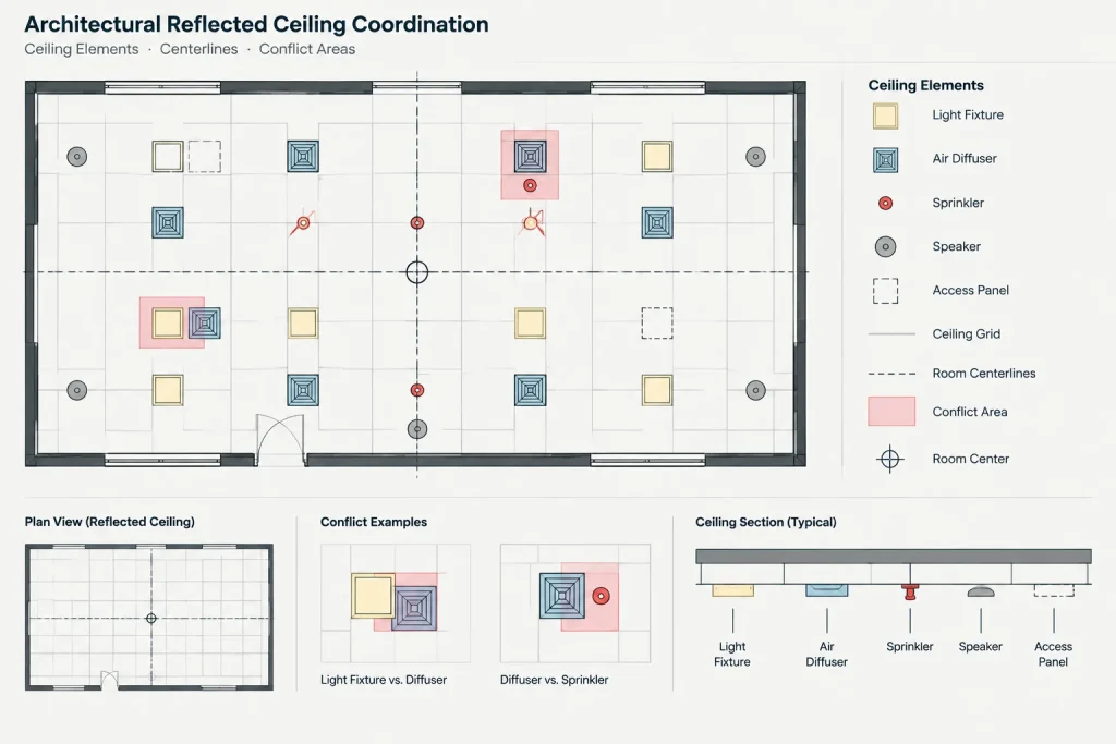
Choose the controlling relationship intentionally rather than centering every pattern by default. A ceiling may need to align with a wall elevation, a reception desk, a sequence of doors, or a lighting concept. Record the controlling intent with dimensions or notes when it would not be obvious to someone reviewing the drawing later.
Keep repeated systems editable. Use suitable blocks, arrays, referenced geometry, or other controlled repetition methods instead of drawing each component independently. However, review the result at boundaries. Small perimeter fragments and awkward intersections often indicate that the starting point or module needs reconsideration.
Place Ceiling-Mounted Elements by Coordination Priority
Many disciplines compete for limited ceiling space. A practical layout begins with fixed or visually dominant constraints and then incorporates elements that have more routing flexibility. The exact priority varies by project, so it should be discussed rather than assumed.
Potential constraints include structural elements, ceiling clouds, folding partitions, operable doors, projectors, decorative fixtures, major ductwork, and access requirements. Once these are understood, coordinate light fixtures, air devices, sprinklers, speakers, sensors, cameras, and access panels.
Use Consultant Drawings as References, Not Decoration
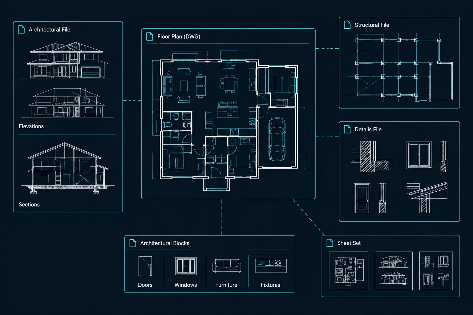
Attach current consultant files using the project coordinate system and agreed reference method. Do not manually reposition consultant backgrounds to make them appear aligned. A mismatch may indicate a coordinate, unit, origin, or revision problem that should be resolved at its source.
Where the architect shows a consultant-owned device for visual coordination, compare it with the consultant’s current drawing. If an architectural layout proposes a desired location, label or communicate that intent through the project’s coordination process. The final location still requires review by the responsible discipline and verification against applicable requirements.
Annotate Ceiling Conditions Without Overloading the Plan
Use ceiling tags to identify recurring types, but do not force every condition into a tag. Complex transitions may need enlarged plans, sections, interior elevations, or details. Tags should correspond to a maintained legend or finish schedule and should not use similar identifiers for unrelated systems.
Dimensions are most valuable when they establish layout intent. Dimension important offsets, controlling centerlines, soffit edges, openings, and feature locations. Avoid dimensioning every repeated grid line or every consultant device when the underlying pattern already controls those positions.
Ceiling elevation notation must distinguish the ceiling plane from floor elevations and other vertical datums. Use one consistent project convention and verify that sloped or stepped conditions are not represented by a single misleading value.
Coordinate the RCP with Other Architectural Views
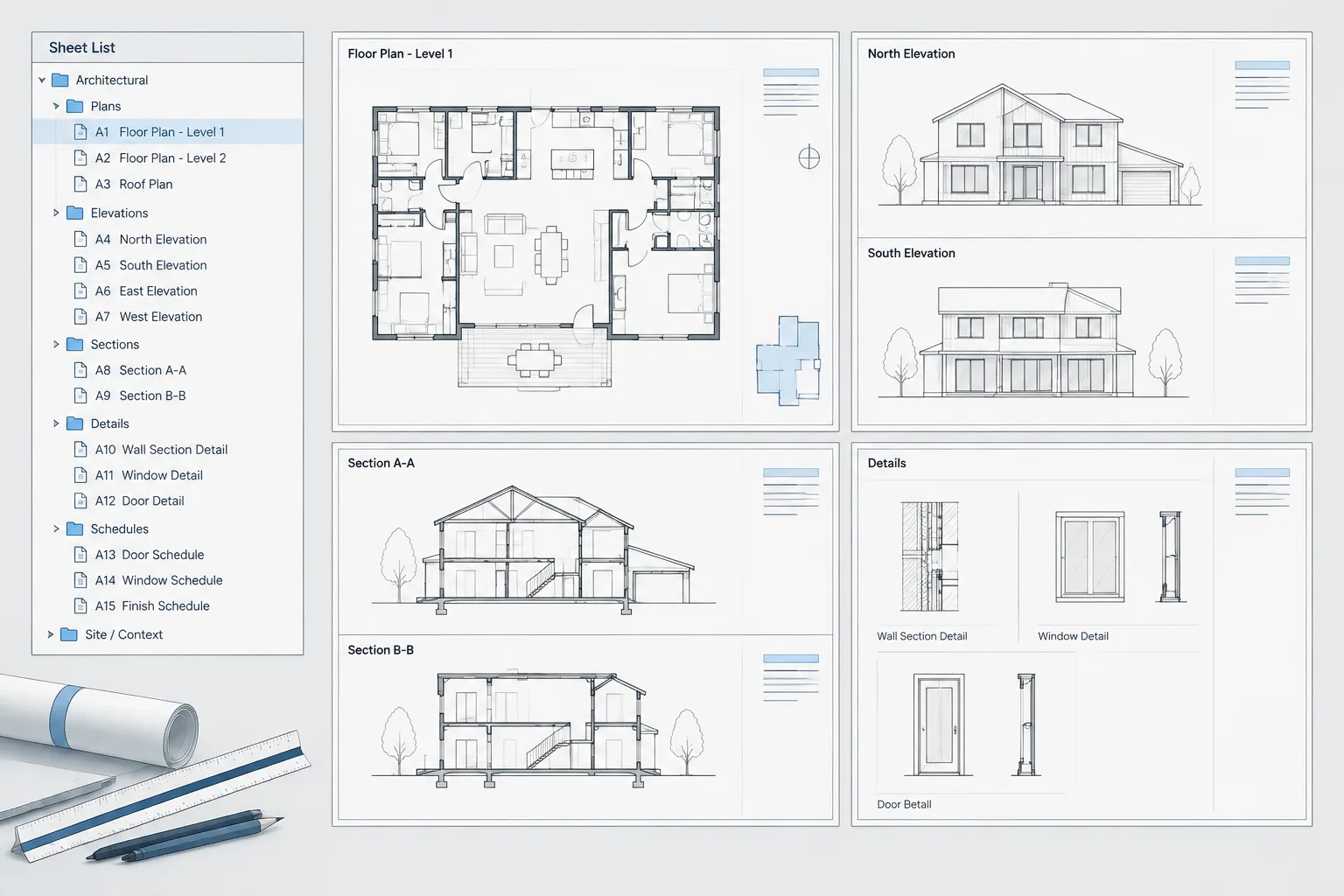
An RCP should agree with the floor plan, sections, interior elevations, finish information, and details. Check that soffits shown overhead appear in wall elevations where visible. Confirm that ceiling transitions have corresponding construction information and that full-height partitions meet the intended overhead condition.
Review doors and tall casework for conflicts with low ceiling features. Coordinate curtain pockets, shade pockets, ceiling recesses, access panels, and built-in equipment with adjacent details. In open-to-structure spaces, verify that the drawing does not imply a concealed ceiling simply because overhead devices are shown in plan.
Perform a Focused Quality-Control Review
Before issuing the RCP, review it both as a CAD file and as a plotted sheet. A drawing that appears clear at full zoom may become illegible at its intended output scale.
- Confirm that the RCP uses the current architectural and consultant backgrounds.
- Check that reflected geometry aligns with walls, columns, shafts, and room limits.
- Look for duplicate symbols, overlapping fixtures, and disconnected ceiling boundaries.
- Verify that ceiling tags correspond with the project legend or schedule.
- Review soffits, level changes, and open areas against sections and elevations.
- Check for conflicts among lights, air devices, sprinklers, speakers, and access panels.
- Confirm that architectural proposals are not mistaken for verified consultant layouts.
- Inspect lineweights, hatch density, text readability, and background screening in a test plot.
- Remove stray construction lines and information outside the intended drawing area.
Build the Drawing Around Coordination, Not Just Appearance
A strong reflected ceiling plan combines design composition with disciplined information management. Clean boundaries, controlled references, purposeful layers, and clear ownership make the drawing easier to revise and coordinate. The final result should explain not only what appears overhead, but also how ceiling zones, fixtures, and architectural features relate across the complete drawing set.
Manage Revisions and Coordination Decisions
RCP coordination should remain traceable as architectural and consultant files are revised. Before comparing layouts, confirm that each reference represents the intended issue and that its position has not been altered locally. Apparent device conflicts may result from an outdated background, an unresolved origin difference, or a ceiling revision that has not reached every discipline.
Record decisions that affect several drawings, such as a relocated soffit, a revised ceiling opening, or a preferred device alignment. The record does not replace the drawings, but it helps the team distinguish an approved change from a temporary coordination proposal.
Separate Design Intent from Verified Information
Architectural composition and technical system requirements often overlap at the ceiling. A proposed arrangement may communicate the desired visual relationship among fixtures and ceiling features, while the responsible consultant evaluates system performance, routing, coverage, access, and applicable requirements. Graphic clarity should make that distinction understandable.
When a coordination issue remains unresolved, avoid disguising it with overlapping symbols or manually adjusted reference graphics. Identify the affected area through the project review process, retain the authoritative source information, and update the RCP after the responsible parties resolve the condition.
Check the Drawing After Every Significant Background Change
- Compare ceiling boundaries with revised wall, shaft, and column locations.
- Review hosted or associated symbols near moved partitions and soffits.
- Confirm that tags, dimensions, and leaders still point to the intended objects.
- Inspect repeated ceiling systems for broken patterns or unintended perimeter pieces.
- Recheck section, elevation, schedule, and detail references affected by the revision.
- Plot the updated view to verify hierarchy, screening, and annotation legibility.
Reflected Ceiling Plan CAD Questions
Is a reflected ceiling plan the same as a lighting plan?
No. An RCP may show light fixtures, but it also communicates ceiling forms, materials, elevation changes, grids, access panels, air devices, and other overhead elements. A lighting or electrical plan may contain additional circuiting, controls, connections, and discipline-specific information.
Should the floor plan be copied into the RCP file?
A controlled reference is generally easier to coordinate than duplicated plan geometry. Referencing helps the RCP follow current walls, columns, openings, and room limits while allowing the background appearance to be managed separately.
Should consultant devices be redrawn on architectural layers?
Consultant information should normally remain identifiable by source and ownership. Architectural graphics may communicate a preferred visual arrangement, but they should not silently replace verified discipline information. The project team should resolve differences through its coordination process.
Why do ceiling symbols become difficult to read?
Common causes include an overly dark floor-plan background, dense hatch patterns, overlapping discipline symbols, inconsistent symbol graphics, and insufficient separation between geometry and annotation. Reviewing a plotted sheet often reveals problems that are not obvious while zoomed into the CAD file.
How should a sloped or stepped ceiling be represented?
Use plan graphics to identify boundaries and transitions, then support the condition with clear notation and related sections, elevations, or details. A single ceiling tag should not imply that a changing plane is uniform.
What should be checked when a referenced plan no longer aligns?
Check the current file revision, coordinate method, origin, units, and reference path before moving anything manually. Local repositioning can conceal the underlying problem and create further inconsistencies when the reference is updated.