
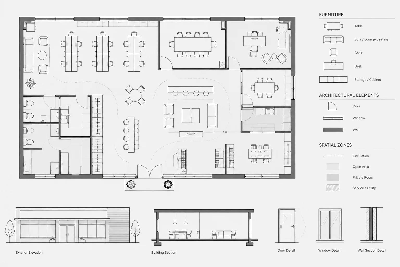
A coordinated furniture plan connects space planning with the architectural background and related building systems. It shows how occupants are expected to use a room while distinguishing movable items from fixed construction.
This guide explains a practical CAD workflow for selecting furniture blocks, organizing layers, representing operational space, managing annotations, and reviewing coordination conflicts. Use the process as a drafting and quality-control framework, then verify product information and project requirements with the responsible design team.
A furniture plan does more than show where chairs and tables might fit. It communicates how rooms are intended to function, helps the design team evaluate circulation, and provides a reference for power, lighting, equipment, and interior coordination. When the plan is prepared carefully, it can also reveal conflicts that are difficult to recognize in an empty architectural floor plan.
The drafting challenge is to keep the furniture plan useful without presenting movable objects as fixed construction. A reliable workflow separates architectural backgrounds, furniture geometry, clearance zones, and annotations while maintaining coordination with the rest of the drawing set.
Define the purpose of the furniture plan
Start by identifying what the drawing must communicate. A preliminary space-planning plan may use generic furniture to test capacity and circulation. A design-development plan may identify furniture types, orientation, and coordination requirements. A procurement-oriented plan may require item tags and a separate furniture, fixtures, and equipment schedule.
The intended use affects the amount of detail shown. Generic planning blocks may be appropriate during early design, but they should not be mistaken for verified product footprints. Conversely, highly detailed manufacturer geometry can make a general architectural plan difficult to read and unnecessarily increase the DWG file size.
Clarify whether the plan includes:
- Movable furniture such as desks, tables, seating, beds, and storage units
- Owner-provided equipment or appliances
- Built-in casework and fixed millwork
- Clearance and circulation zones
- Furniture tags, room names, or equipment identifiers
- Power, data, floor-box, or lighting coordination references
Built-in elements are usually part of the architectural construction documents and should remain coordinated with plans, elevations, sections, and details. Movable furniture may be controlled by the architect, interior designer, owner, or a separate vendor. The drawing should make that responsibility clear.
Prepare a controlled architectural background
Use a current architectural floor plan as the furniture plan background. In a multi-file project, this is commonly managed as an external reference so that wall, door, and room changes can flow into the furniture drawing without duplicating base geometry.
Display enough background information to support placement decisions, including walls, doors, windows, columns, and fixed fixtures. Reduce the graphic emphasis of background elements if necessary so that furniture remains easy to identify. Avoid deleting or manually redrawing background objects merely to improve appearance; graphic control should not break coordination.
Before laying out furniture, verify the drawing units, reference alignment, current room boundaries, and door swings. An attractive arrangement built on an outdated plan is not a coordinated arrangement.
Select and standardize furniture CAD blocks
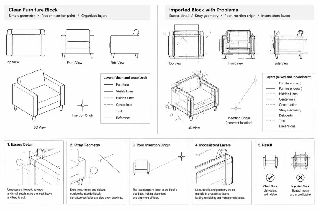
Furniture blocks should represent a consistent planning footprint and orientation. Inspect downloaded or inherited DWG blocks before adding them to the project library. A block may look acceptable in a preview but contain incorrect units, distant stray objects, excessive internal detail, unwanted text, or unrelated layers.
Review each block for:
- Correct units and insertion scale
- A practical insertion point
- Consistent default orientation
- Clean, closed, and readable plan geometry
- Appropriate graphic detail for the plotted drawing scale
- Objects assigned to suitable layers and properties
- Text or attributes that remain readable after rotation or mirroring
Use descriptive block names that distinguish form and function without implying an unverified manufacturer or product. If several blocks represent related options, apply a consistent naming structure so users can locate and replace them efficiently.
Generic planning blocks should remain visibly generic. If a real product is later selected, compare its verified dimensions, access requirements, and service needs with the planning block before treating the layout as final.
Build the layout from room function
Place the primary furniture item first. This may be a bed in a sleeping room, a worktable in a studio, a conference table in a meeting room, or a service counter in a reception area. Orient that item in relation to entrances, views, presentation surfaces, windows, and fixed building elements.
Add supporting pieces only after the main arrangement is established. This creates a clearer hierarchy and reduces the temptation to fill every open area with furniture. Consider how occupants approach, use, and leave each item rather than judging the plan only as a static composition.
Use alignment deliberately
Furniture layouts usually read more clearly when related objects share meaningful alignments. Align workstation rows, chair groups, table edges, and storage units to walls, planning grids, or one another. Avoid tiny accidental offsets and nearly parallel rotations that look like drafting errors.
Copying or arraying repeated items can improve consistency, but repeated geometry still needs room-by-room review. A layout that works in one bay may conflict with a column, door, glazing condition, or equipment location in another.
Keep movable and fixed elements distinct
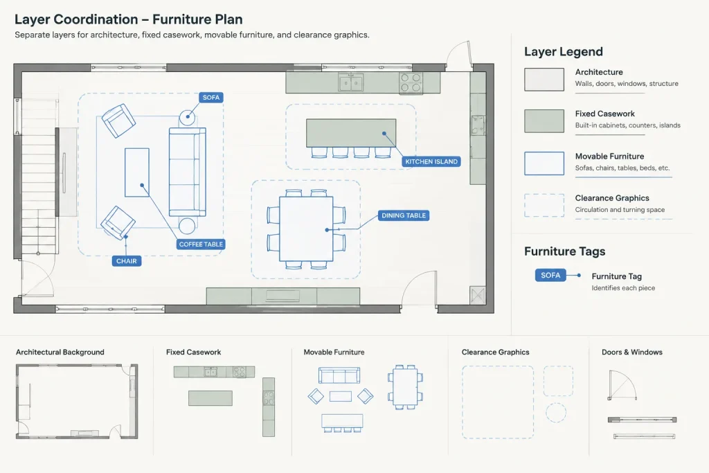
Do not combine movable furniture and fixed millwork into the same anonymous geometry. Their installation, documentation, and coordination responsibilities differ. Use separate blocks or layers and identify fixed components through the appropriate architectural drawings.
Represent clearances without clutter
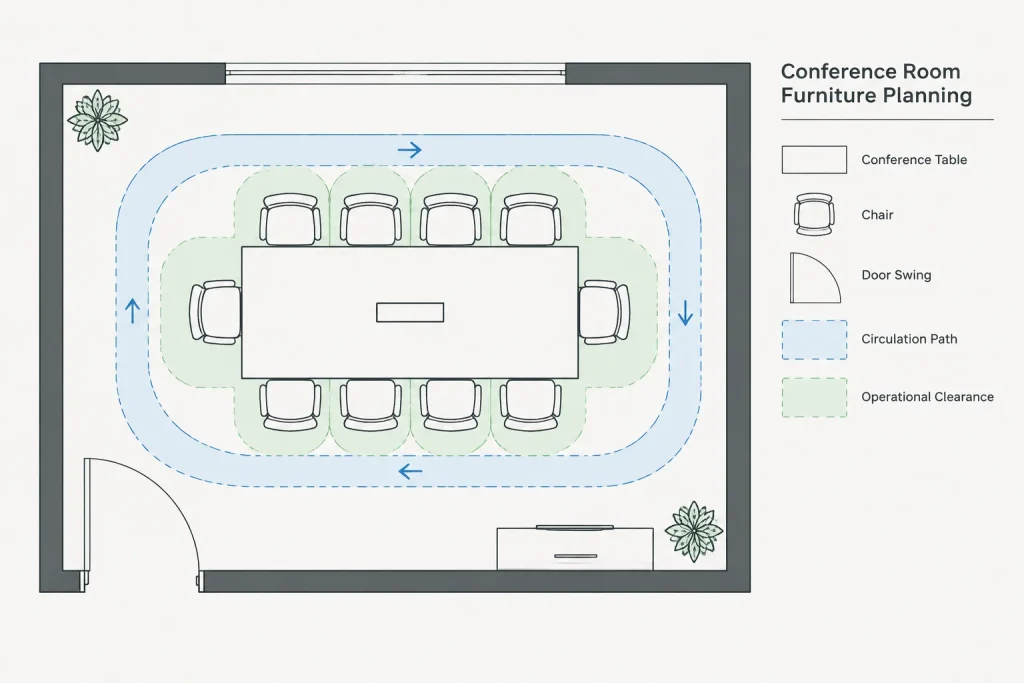
A furniture block shows the physical footprint of an object, but it does not necessarily show the space required to approach or use it. Chairs may move away from tables, cabinet doors may open, equipment may need service access, and occupants need usable circulation between furniture groups.
Where these zones matter, draw them as separate, controllable geometry rather than building them permanently into every visible furniture outline. A clearance layer can be displayed during planning and quality control, then hidden or simplified on the issued sheet if it would obscure the final drawing.
Do not assume that a generic clearance shape proves code compliance or accessibility. Required spaces depend on the project, jurisdiction, room use, selected products, and applicable criteria. Treat CAD zones as coordination tools and verify the governing requirements separately.
Organize layers and object properties
A practical layer structure should allow users to control different furniture-plan functions without selecting objects individually. The exact naming convention should follow the project CAD standard, but the information can be divided by purpose.
| Content group | Typical use | Coordination note |
|---|---|---|
| Furniture outlines | Primary movable items shown in plan | Keep visually stronger than optional clearance graphics |
| Furniture clearance zones | Movement, approach, and operational areas | Control separately for working and presentation views |
| Furniture tags | Identifiers linked to a legend or schedule | Check that every tag resolves to a defined item |
| Owner or vendor equipment | Items outside the architectural construction scope | Identify responsibility and confirm current information |
| Fixed casework | Built-in components requiring construction coordination | Coordinate with elevations, sections, and details |
Keep object properties consistent with the layer strategy. Unexplained object-level color, linetype, or lineweight overrides make future editing and plotting less predictable.
Coordinate with doors, windows, and building systems
Review the furniture plan together with the architectural and consultant drawings. Furniture should not prevent doors from operating, conceal required access to panels, block intended glazing, or occupy space needed for fixed equipment. Tall storage and shelving may also affect switches, outlets, thermostats, wall devices, and visual relationships that are not obvious in plan alone.
Furniture often influences electrical and lighting layouts. Workstations may need nearby power and data, tables may relate to floor service locations, and reading or task areas may affect lighting placement. Communicate these dependencies without casually moving consultant elements in the architectural file. Mark the issue, coordinate with the responsible discipline, and update the drawings from an agreed decision.
Also compare the plan with interior elevations where furniture interacts with wall-mounted displays, marker surfaces, shelving, artwork, or millwork. A plan may show adequate horizontal space while an elevation reveals a height or alignment conflict.
Tag only what the project can manage
Item tags are useful when they connect the drawing to a maintained legend, schedule, or procurement document. They become misleading when codes are assigned inconsistently or the schedule is not updated.
Decide whether tags identify a furniture type, an individual item, or a procurement package. Apply that rule consistently. Avoid placing explanatory notes inside reusable furniture blocks unless the text is intended to appear for every instance. Separate annotation is generally easier to position and control.
Perform a final furniture-plan review
Before issuing or sharing the plan, inspect both the model and the plotted sheet. A useful review includes the following checks:
- The architectural background is current and correctly aligned.
- Furniture blocks use verified units and consistent orientation.
- Door swings, circulation paths, and operational zones have been reviewed.
- Fixed casework is distinguishable from movable furniture.
- Furniture does not visibly conflict with columns, glazing, fixtures, or equipment.
- Relevant power, data, lighting, and wall-device relationships have been coordinated.
- Tags match the current legend or schedule.
- Clearance graphics are shown only where useful and do not imply unverified compliance.
- Lineweights and text remain readable at the intended plot scale.
- Unused blocks, stray geometry, and unnecessary detail have been removed.
A well-drafted furniture plan should explain how the space is expected to work while remaining flexible enough to accommodate design changes. Clean blocks, controlled layers, visible clearance logic, and disciplined coordination make the drawing more valuable than a collection of furniture symbols placed over a floor plan.
Manage furniture-plan changes throughout the project
Furniture layouts rarely remain static. Room boundaries, door locations, equipment selections, and user requirements may change as the design develops. Treat each revision as a coordination event rather than simply shifting blocks until the plan looks balanced.
When the architectural background changes, review affected rooms systematically. Confirm that relocated furniture still relates correctly to entrances, fixed elements, operational zones, and building services. Pay particular attention to copied arrangements because a repeated layout can preserve a conflict across several rooms.
Record assumptions and unresolved decisions
Generic CAD blocks often represent planning assumptions rather than selected products. Make that distinction clear in the drawing notes, block naming system, or project documentation. Unresolved furniture dimensions, equipment responsibilities, and service connections should remain visible to the team instead of being implied by polished geometry.
For significant conflicts, record the room, affected item, related discipline, and required decision. This creates a more reliable coordination trail than informal markups that may become separated from the current drawing.
Prepare a clean handoff
Before sharing the DWG, remove abandoned test layouts and confirm that required references are available. Check that furniture blocks, tags, clearance graphics, and fixed elements remain separable through the project layer system.
The receiving user should be able to understand which objects are movable, which items are built in, what information is provisional, and where coordination is still pending. That clarity is essential whether the file moves to another designer, a consultant, an owner, or a furniture vendor.
Furniture plan CAD questions
What is the difference between a furniture plan and a floor plan?
A floor plan documents the architectural arrangement of walls, openings, fixtures, and other building elements. A furniture plan uses that background to communicate room use, furniture placement, circulation, and coordination needs.
Should furniture be drawn directly in the architectural floor-plan file?
The appropriate file structure depends on the project CAD standard. A separate furniture drawing with a controlled architectural reference can make updates and graphic control easier, while smaller projects may use carefully separated layers within a shared file.
Can downloaded furniture DWG blocks be used without editing?
They should be inspected before project use. Confirm units, insertion point, orientation, geometry, layers, text, and level of detail. A visually convincing block may still contain drafting problems or represent an unverified product footprint.
Should clearance zones be included inside furniture blocks?
Usually, clearance and operational areas are easier to manage as separate geometry. This allows them to be displayed during layout review and controlled independently for presentation drawings.
How should built-in casework appear on a furniture plan?
Built-in casework should remain distinguishable from movable furniture and coordinated with the architectural plans, elevations, sections, and details. Its drawing classification should reflect that it is fixed construction rather than a movable furnishing.
Does a clearance outline demonstrate accessibility or code compliance?
No. A CAD clearance outline is a planning and coordination aid. Compliance depends on the applicable requirements, project conditions, room use, and verified product information.
When are furniture tags useful?
Tags are useful when each identifier connects to a maintained legend, schedule, or procurement record. They should follow a consistent rule and be updated whenever the corresponding item information changes.
