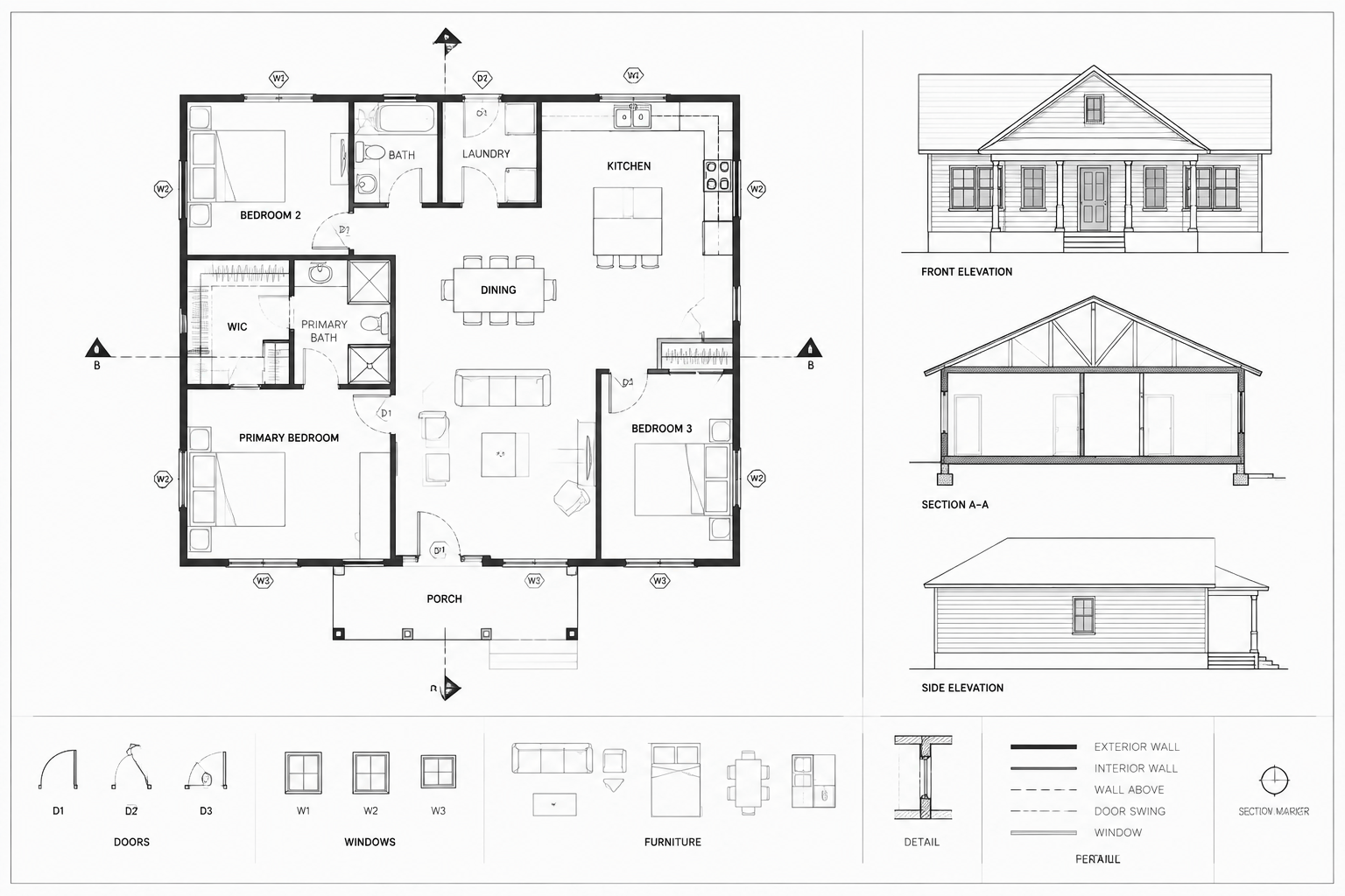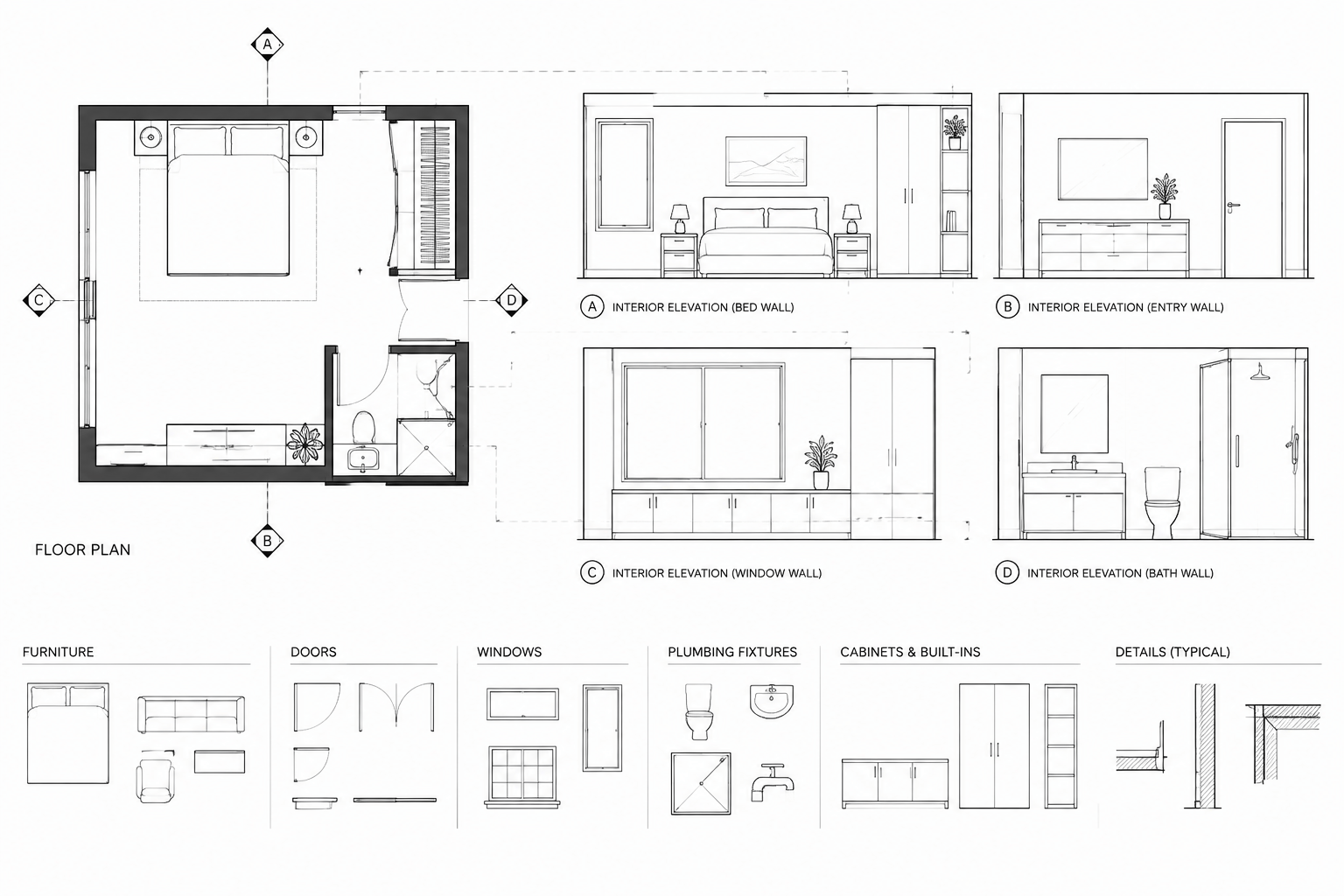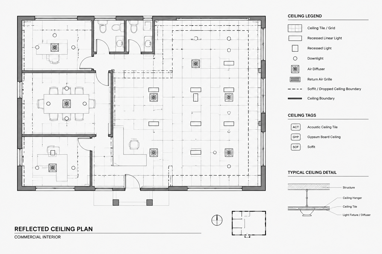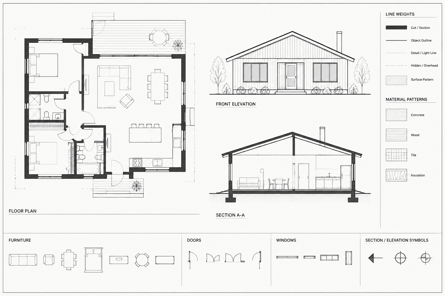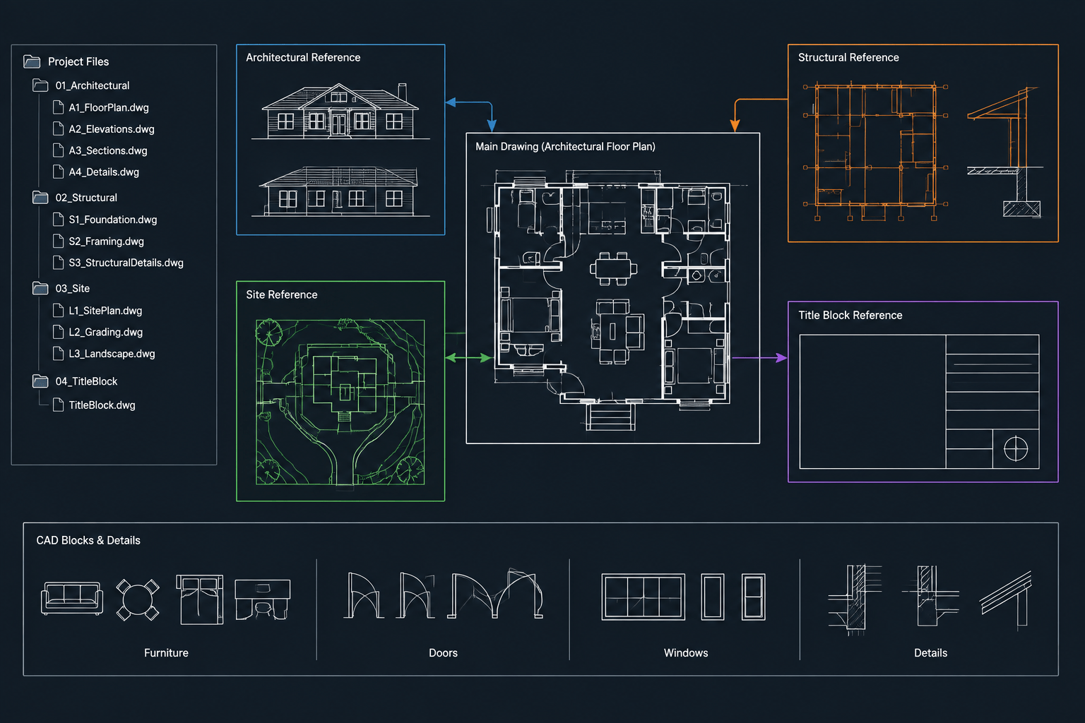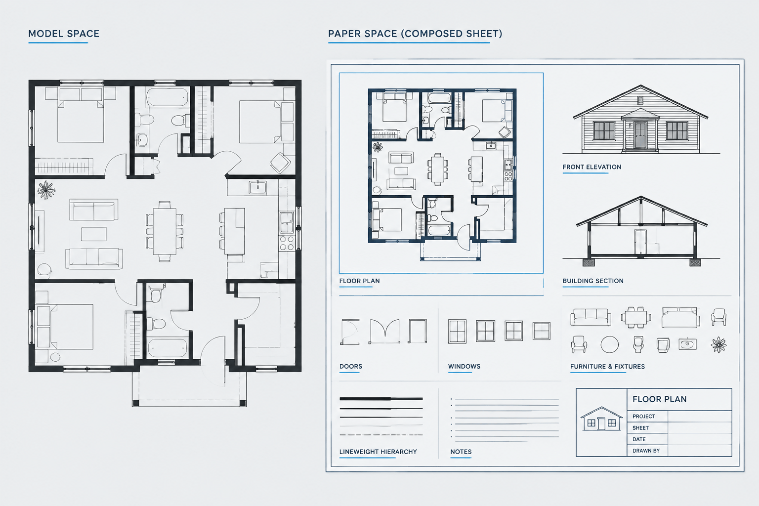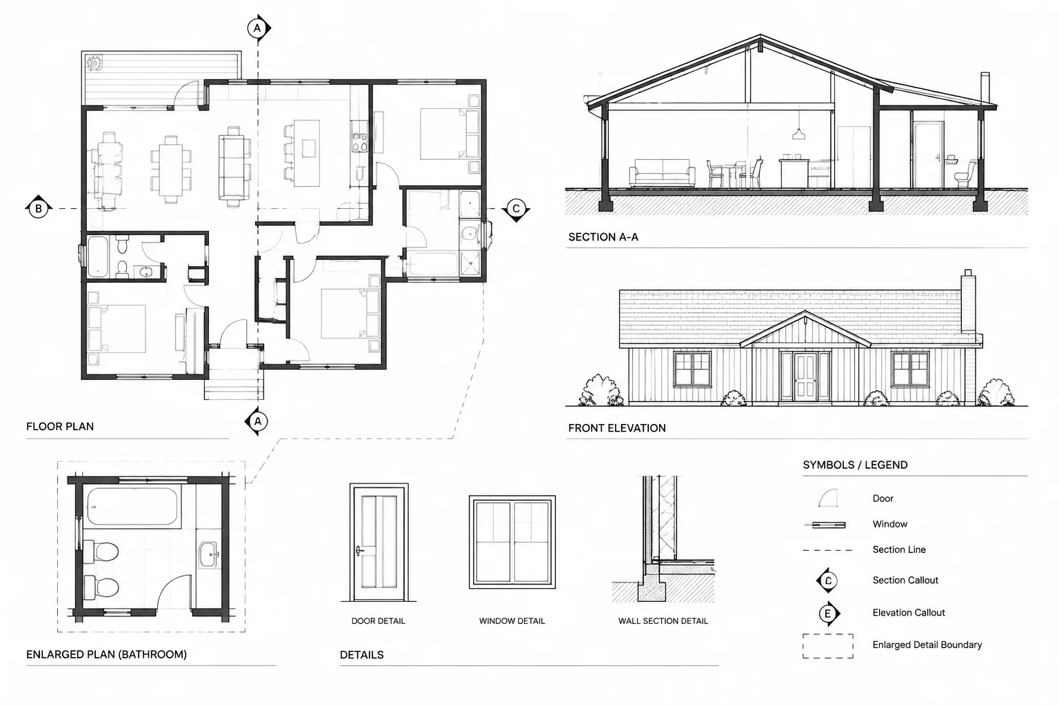
Coordinating architectural CAD callouts requires more than matching a symbol to a sheet label. The cut location, viewing direction, destination title, referenced content, and graphic hierarchy must communicate the same intent throughout the drawing set.
This guide explains how to coordinate architectural CAD callouts from initial placement through final review. It covers plans, elevations, sections, enlarged views, and details while emphasizing reusable symbols, bidirectional checking, revision control, and clear drawing navigation.
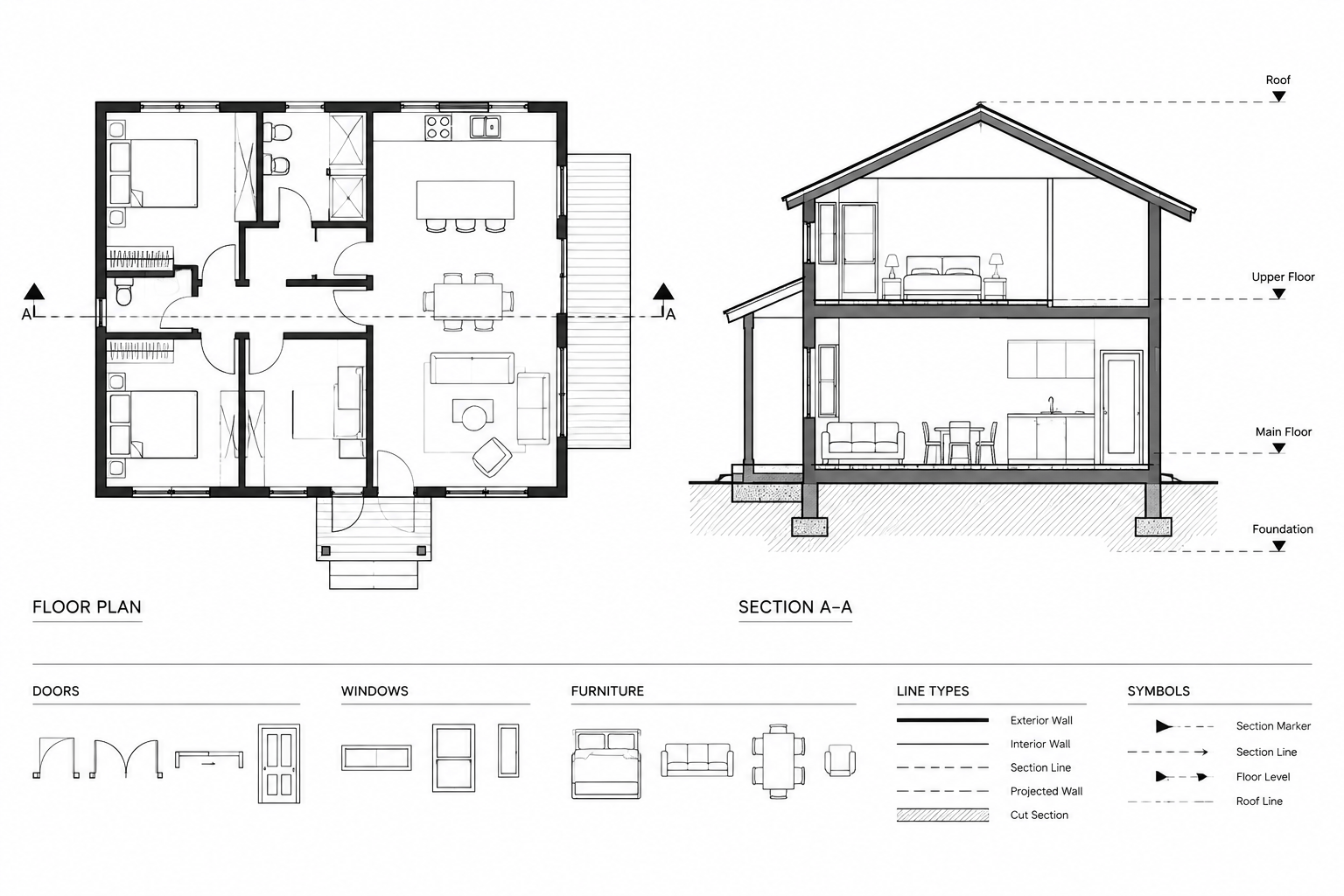
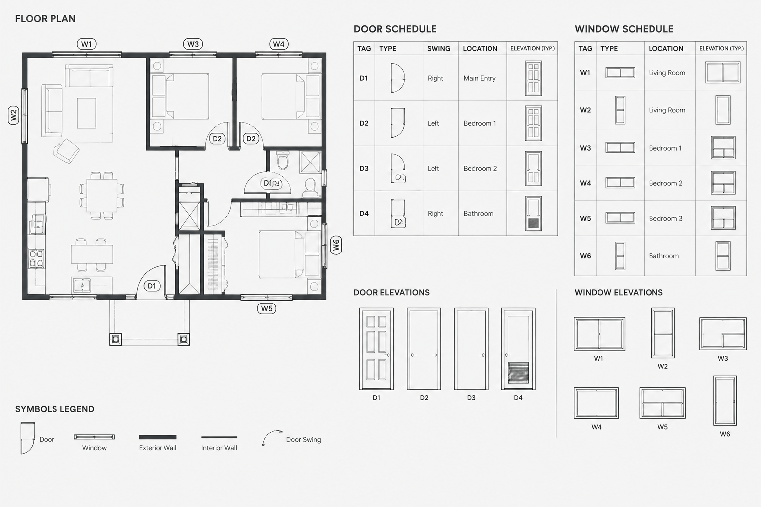
Architectural drawing callouts connect floor plans, elevations, sections, enlarged plans, and details into one navigable document set. A callout may look like a simple symbol, but it carries an important coordination promise: the referenced view exists, its identifier is correct, and the view shows the location or assembly indicated by the marker.
When callouts are placed casually, drawing sets develop broken references, duplicated view numbers, inconsistent symbols, and markers that point to outdated details. A reliable CAD workflow treats each callout as part of a coordinated reference system rather than as isolated annotation.
What an architectural callout communicates
A typical callout identifies a related drawing view and tells the reader where to find it. Depending on office conventions and the type of view, the marker may include:
- A view or detail identifier.
- The sheet identifier on which the referenced view appears.
- A directional arrow or viewing line.
- A boundary showing the area included in an enlarged view.
- A graphic indication of the cutting plane for a section.
- A reference note explaining the subject of the callout.
The graphic form varies among drawing standards, project types, and offices. The underlying principle remains the same: the symbol on the source drawing must correspond clearly to a labeled destination view.
Distinguish the main callout types
| Callout type | Primary purpose | Key coordination issue |
|---|---|---|
| Building section | Shows a major vertical cut through the building | Cut location and viewing direction must agree with the section content |
| Wall or assembly section | Explains a focused vertical construction condition | The referenced assembly must match the plan and larger-scale details |
| Exterior or interior elevation | Shows a face viewed in a stated direction | The marker orientation must correspond to the elevation shown |
| Enlarged plan | Provides more space for dimensions, notes, and components | The callout boundary should include the relevant scope without implying unrelated work |
| Detail callout | Identifies a small condition requiring additional explanation | The detail must represent the actual condition at the marker location |
| Reference-only callout | Directs the reader to an existing related view | It should not suggest that a new cut or view was created when it was not |
Build a consistent CAD callout family
Create a coordinated set of reusable symbols rather than drafting each marker from separate lines and text. The family can include section heads, elevation markers, detail bubbles, enlarged-plan boundaries, and continuation symbols.
Each symbol should use a common visual language. Coordinate text style, text placement, lineweight intent, masking behavior, and the relationship between the view and sheet identifiers. Consistency helps readers recognize references quickly and makes errors easier to spot during review.
Keep editable information separate from fixed graphics
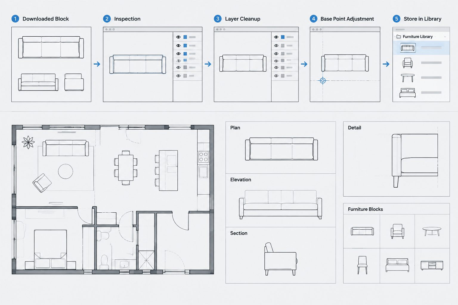
The outline, arrow, and divider can remain fixed within a reusable CAD block. View identifiers, sheet identifiers, and optional reference text should remain easy to edit. Block attributes are useful when they fit the office workflow, but ordinary text may be appropriate in simpler files. In either case, avoid exploding symbols merely to change their labels.
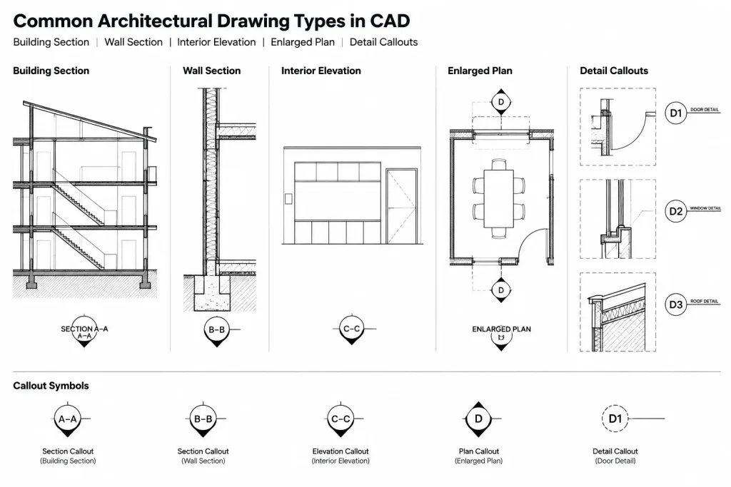
Use a logical insertion point. For a section marker, the insertion point might relate to the cut line or marker head. For an enlarged-plan callout, it might relate to the callout boundary or label. A predictable insertion point makes symbols easier to place, rotate, replace, and audit.
Start with the source view, not the sheet label
Place the callout where the condition originates. A section marker begins on the plan through which the section is taken. An interior elevation marker begins in the room being viewed. An enlarged-plan boundary begins around the area requiring additional information.
Before assigning a destination reference, confirm three things:
- The proposed view is necessary and does not duplicate another view.
- The callout location includes the condition the view is intended to explain.
- The viewing direction is unambiguous.
Avoid assigning final identifiers too early if sheet organization is still changing. Temporary identifiers may be used during development, but they should be easy to distinguish from issue-ready references and must be resolved before publication.
Create and label the destination view
After establishing the source marker, create the corresponding section, elevation, detail, or enlarged plan. Give the destination view a title that describes its content rather than relying only on an identifier. A descriptive title helps reviewers determine whether the callout leads to the expected information.
The destination view label should agree exactly with the source marker. If the source points to a particular view on a particular sheet, that combination must appear at the destination. Similar-looking characters, improvised abbreviations, and inconsistent sheet naming can create subtle reference errors.
Coordinate both directions
Callout checking is bidirectional. Do not stop after confirming that every marker points to a view. Also verify that every placed view has a valid source or a clear reason for existing independently.
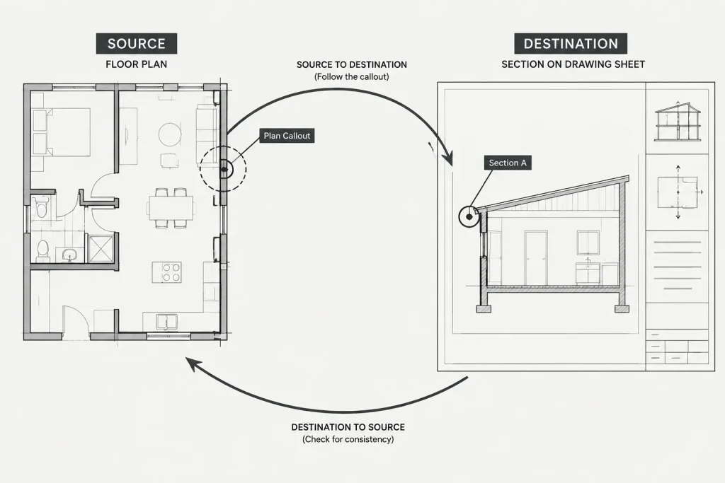
- Source-to-destination check: Follow each callout and confirm that the referenced view exists.
- Destination-to-source check: Review each view and confirm where it is called from.
- Content check: Confirm that the destination actually shows the marked location and direction.
This process detects orphan views, obsolete details, and reused references whose geometry no longer matches the project condition.
Control callout visibility and graphic hierarchy
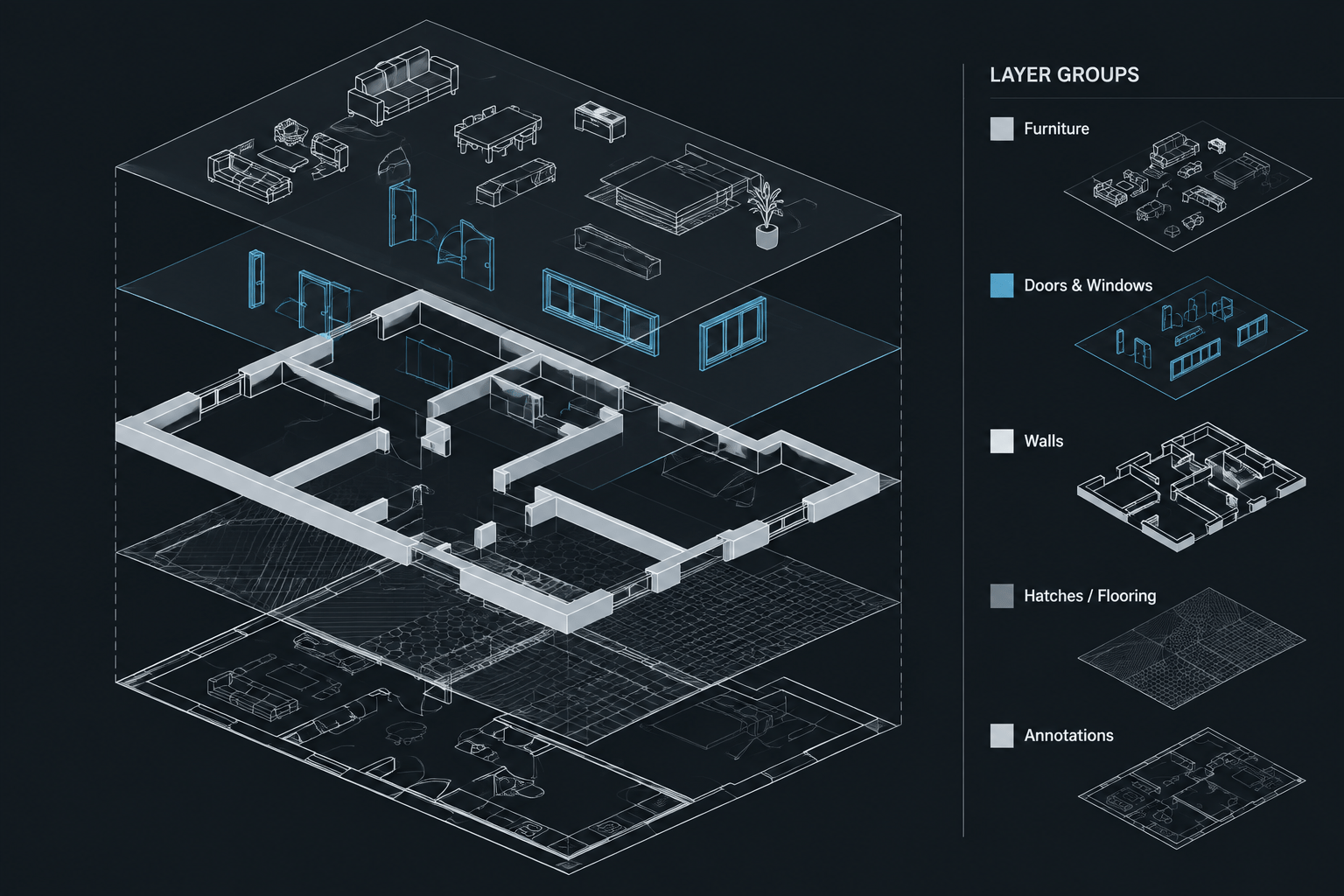
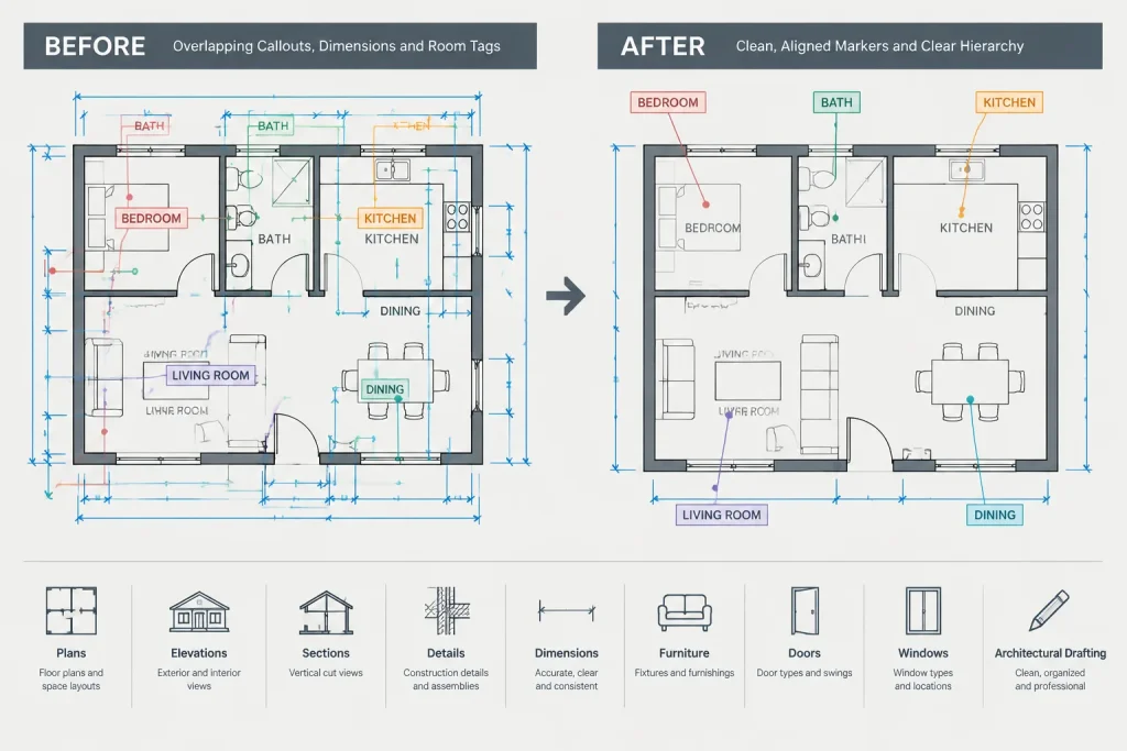
Callouts should be visible without overpowering the building geometry. Place callout components on appropriate annotation layers so their visibility and plotted appearance can be managed consistently. Separate symbols from model geometry; do not place section heads, detail bubbles, or reference text on wall, door, or furniture layers.
Use hierarchy to distinguish major cuts from secondary references. A building section may need greater visual emphasis than a small detail marker. However, differences should be systematic rather than based on arbitrary edits to individual symbols.
Keep labels clear of dimensions, room tags, door tags, and dense hatch patterns. When a marker must be moved for legibility, preserve its relationship to the actual cut, boundary, or viewing direction. Leader lines and jogs should clarify that relationship rather than create uncertainty.
Manage repeated and dependent views
One view may be referenced from several locations when the condition is genuinely the same. Before reusing a detail, compare the surrounding construction, orientation, material transitions, and adjacent components. A visually similar condition is not automatically identical.
If multiple callouts point to one typical detail, make the scope of that detail clear in the drawing notes or title. Do not use a generic detail to conceal unresolved differences between locations. Where conditions vary, create separate views or supplement the typical detail with project-specific information.
Dependent views also require care. An enlarged plan may reference interior elevations, which may then reference millwork or finish details. Review the chain as a complete path. A correct first reference does not compensate for a broken reference later in the sequence.
Update callouts when sheets change
Sheet composition commonly changes during design and documentation. Views may move, be deleted, or receive new identifiers. Whenever a destination changes, update every source marker that points to it.
A practical change workflow is:
- Record which view is being moved, renamed, replaced, or deleted.
- Locate all source callouts associated with that view.
- Update the destination label and source references together.
- Check any secondary callouts contained within the moved view.
- Plot or preview the affected sheets to review readability.
- Remove superseded symbols and temporary coordination notes.
Do not assume that changing a title beneath a view updates unrelated text elsewhere in the drawing set. Whether references are manually entered or data-driven, they still require visual verification.
Use a callout coordination register
For larger drawing sets, maintain a simple register during production and quality control. It can be a worksheet, drawing table, or project database, depending on the team workflow.
| Register field | What to record |
|---|---|
| View identifier | The unique label assigned to the destination view |
| View title | A concise description of the view content |
| Destination sheet | The sheet carrying the view |
| Source location | The plan, elevation, section, or detail containing the callout |
| View type | Section, elevation, enlarged plan, or detail |
| Status | Proposed, developed, checked, moved, or removed |
The register is not a substitute for reviewing the drawings. It is a tracking tool that makes duplicated identifiers and missing destinations easier to find.
Final pre-issue callout checklist
- Every callout has a legible view and sheet reference.
- Every referenced destination view exists on the stated sheet.
- View directions and section cuts agree with the destination content.
- Enlarged-plan boundaries accurately represent the shown scope.
- No two unrelated views use the same identifier on one sheet.
- Deleted or moved views have no remaining obsolete references.
- Repeated details are appropriate for every marked location.
- Markers do not conflict with dimensions, tags, or other annotation.
- Callout layers and plotted graphics follow the project hierarchy.
- Temporary identifiers and coordination notes have been resolved.
A coordinated callout system makes an architectural set easier to read and safer to revise. The essential habit is to treat every marker and destination as a linked pair. By checking location, direction, labeling, content, and sheet placement together, CAD teams can reduce broken references and help readers move confidently through the drawing set.
Make callout coordination part of the drawing workflow
Callout review is most effective when it occurs throughout drawing production rather than only before issue. A reference may be correct when first placed and become inaccurate after a view is moved, a plan is revised, or a construction condition is developed further.
Assign responsibility for checking both ends of each reference. The person editing a destination view should consider where that view is called from, while the person revising a source plan should confirm that its callouts still represent the current geometry. This shared approach reduces the chance that an apparently minor drawing change will create an unresolved reference elsewhere.
Review callouts in context
Do not evaluate a marker only at close drafting scale. Review the complete sheet to see whether the symbol is visually clear, then follow the reference to confirm that the destination answers the question raised at the source. A technically correct label can still be ineffective if it is hidden by other annotation or leads to a view that does not clearly show the marked condition.
- At the source: Check location, boundary, cut line, orientation, label, and nearby annotation.
- At the destination: Check the view identifier, sheet placement, title, orientation, and represented condition.
- Across the reference path: Follow any secondary callouts and confirm that the reader can continue without encountering an obsolete or ambiguous reference.
Separate drafting corrections from design questions
Some callout problems are straightforward drafting errors, such as mismatched labels or duplicated identifiers. Others reveal unresolved design information, such as a detail reused at locations with different assemblies. Record the latter as coordination questions rather than adjusting the annotation to imply that the condition has been resolved.
A clear callout system improves navigation, but it cannot replace accurate view content. The source marker, destination label, and drawing itself must remain coordinated as a complete information chain.
Frequently asked questions about architectural CAD callouts
What is the difference between a section callout and an elevation callout?
A section callout identifies a cutting plane through a building or assembly and indicates the direction of view. An elevation callout identifies a face viewed from a stated direction without implying the same type of cut. Their symbols should make that distinction clear within the project drawing conventions.
Should callout symbols be created as reusable CAD blocks?
Reusable blocks can improve consistency in symbol geometry, text placement, and insertion behavior. Information that changes between references, such as view and sheet identifiers, should remain editable without requiring the symbol to be exploded.
How should a moved view be coordinated?
Update the destination label and every source callout associated with the view. Then inspect callouts inside the moved view, review the affected sheets, and remove any superseded references or temporary notes.
Can several callouts reference the same detail?
Yes, when the represented condition is genuinely applicable at every marked location. Compare assemblies, orientation, adjacent components, and transitions before treating a detail as typical. Similar appearance alone does not establish that the conditions are identical.
Why should callouts be checked in both directions?
Following markers to their destinations finds missing or incorrect views. Reviewing destination views back to their sources finds orphaned views, outdated content, and drawings that no longer have a clear reason for inclusion.
Where should callout graphics be placed in a CAD file?
Callout symbols and reference text should be organized on suitable annotation layers rather than mixed with building geometry. This supports consistent visibility, plotting, editing, and quality-control review.