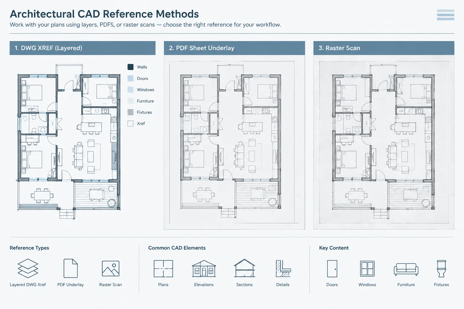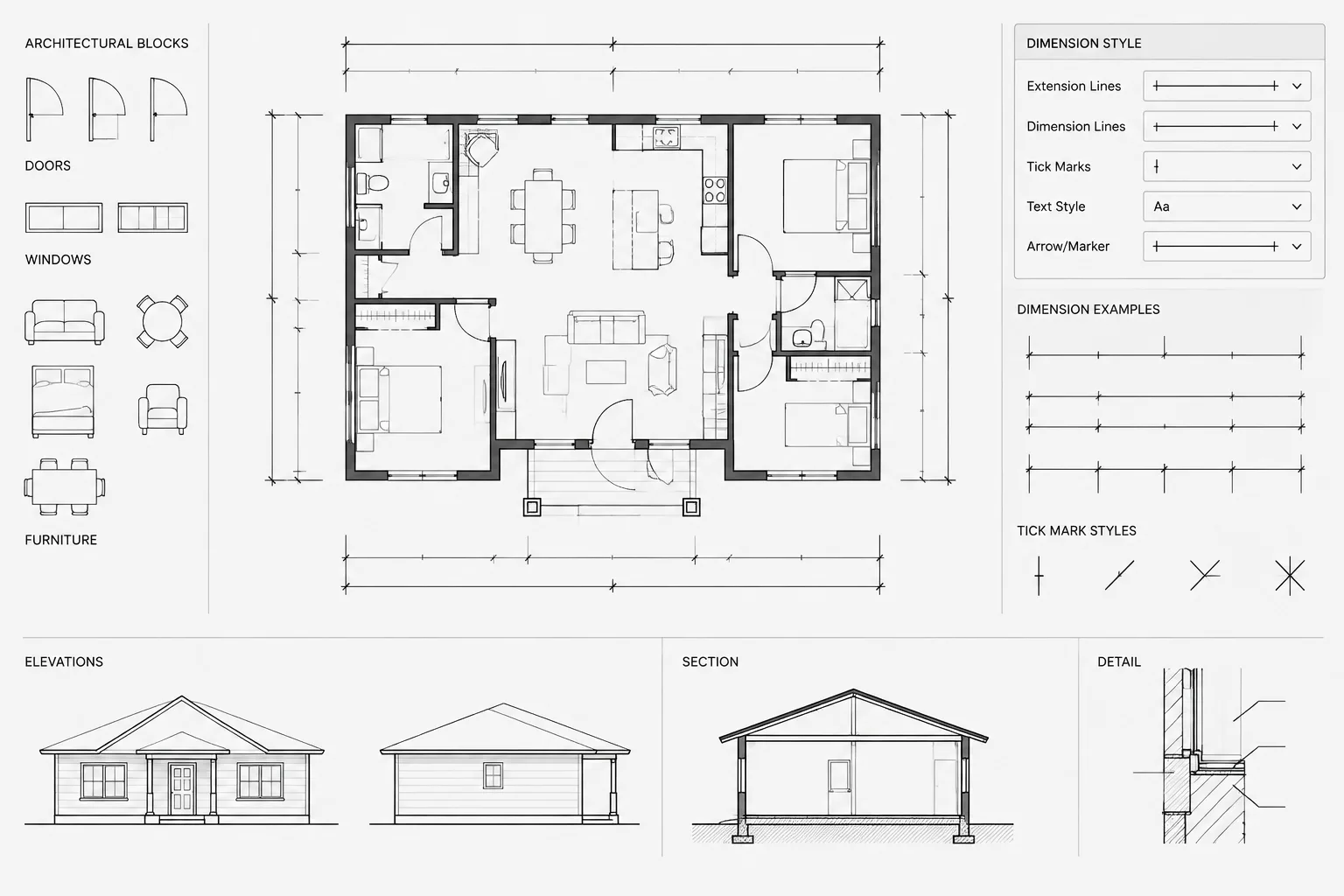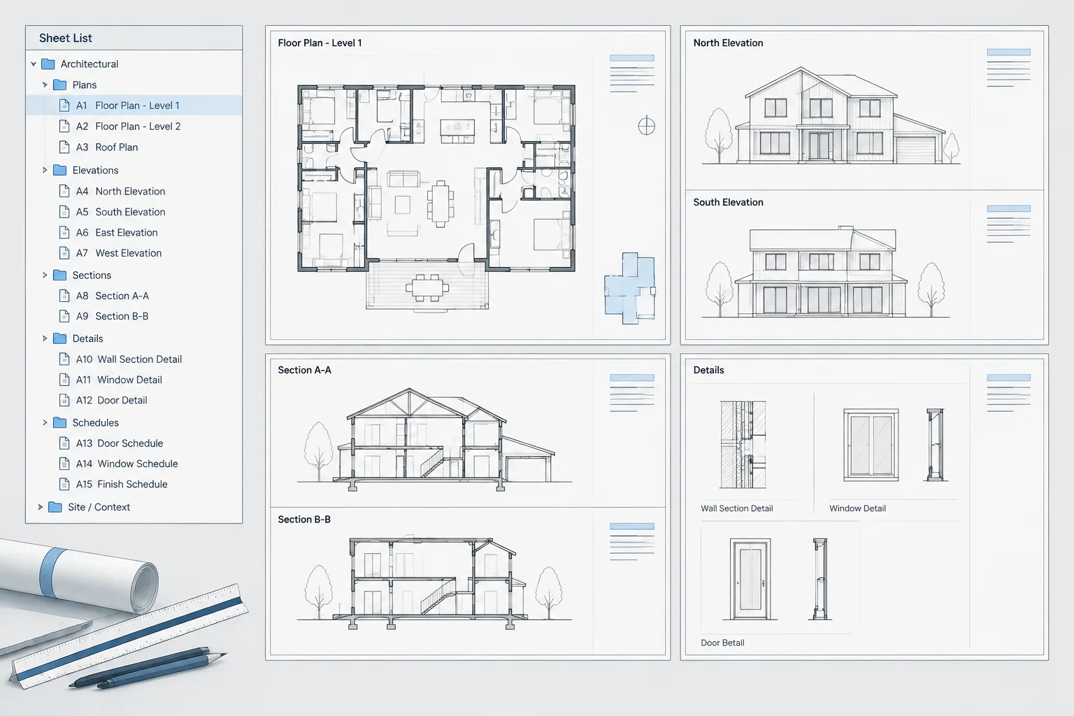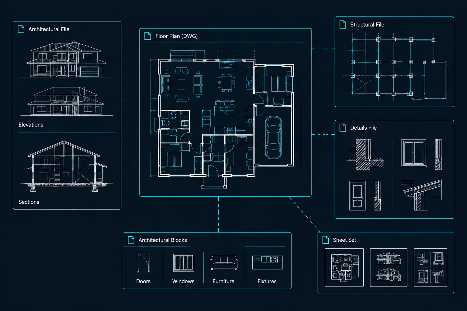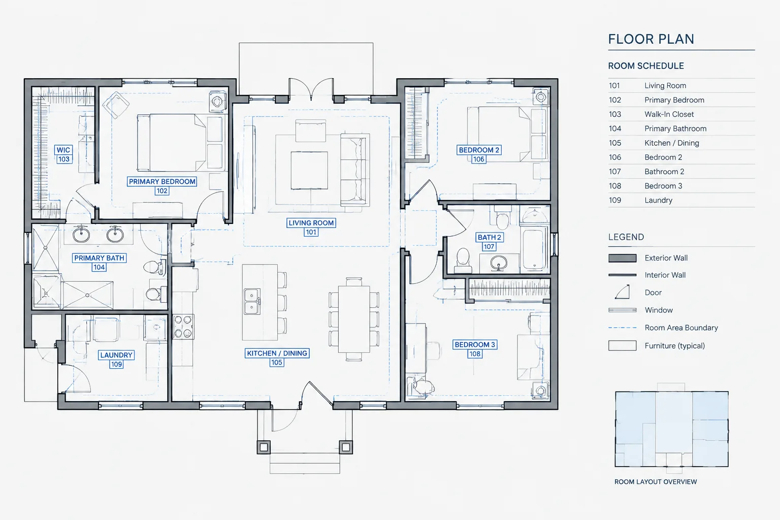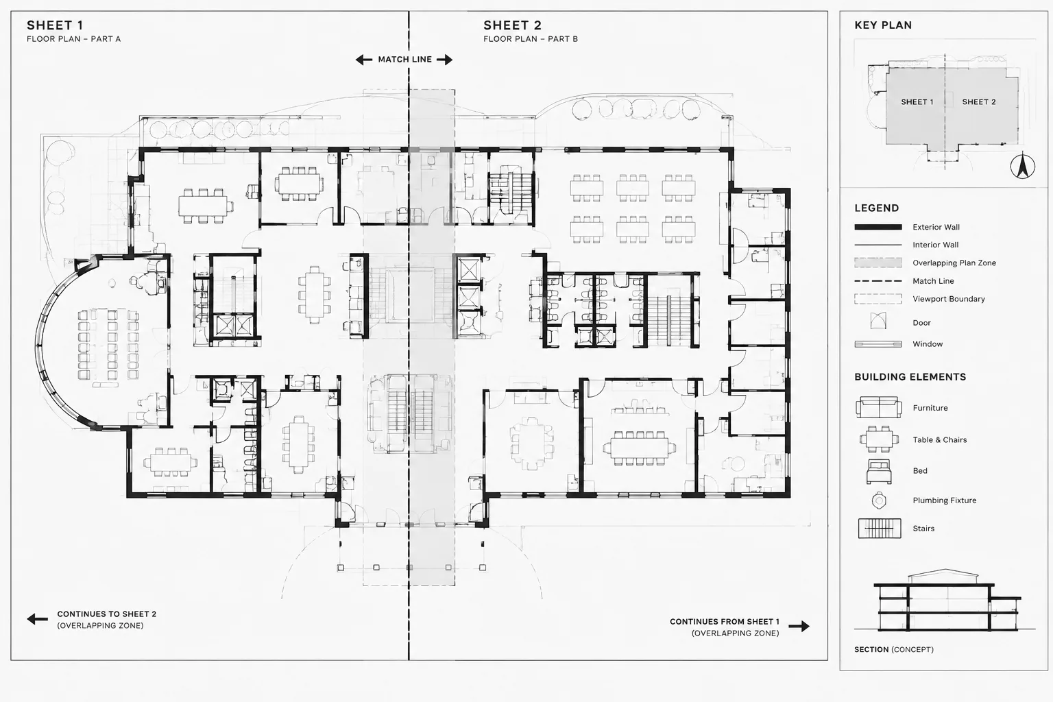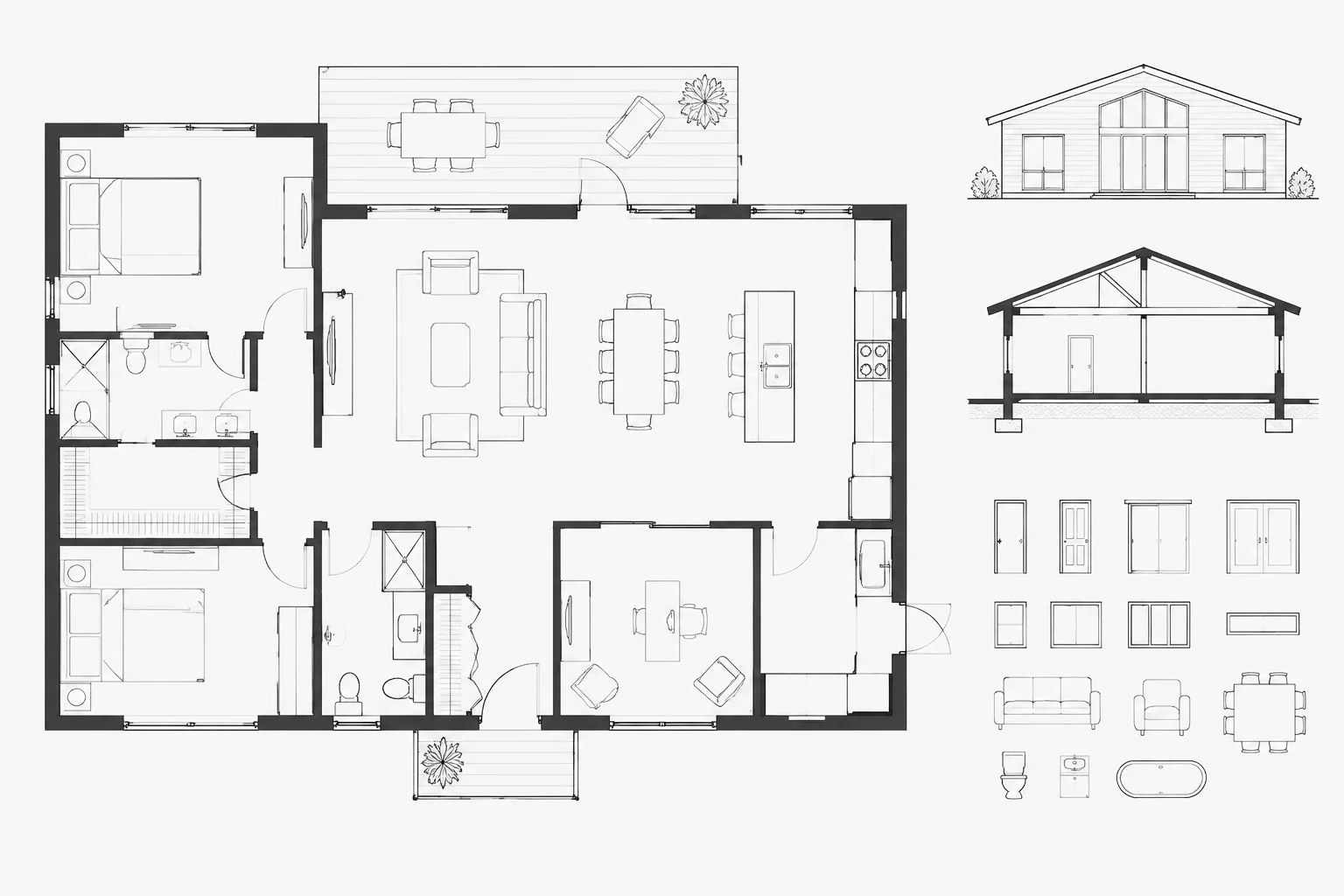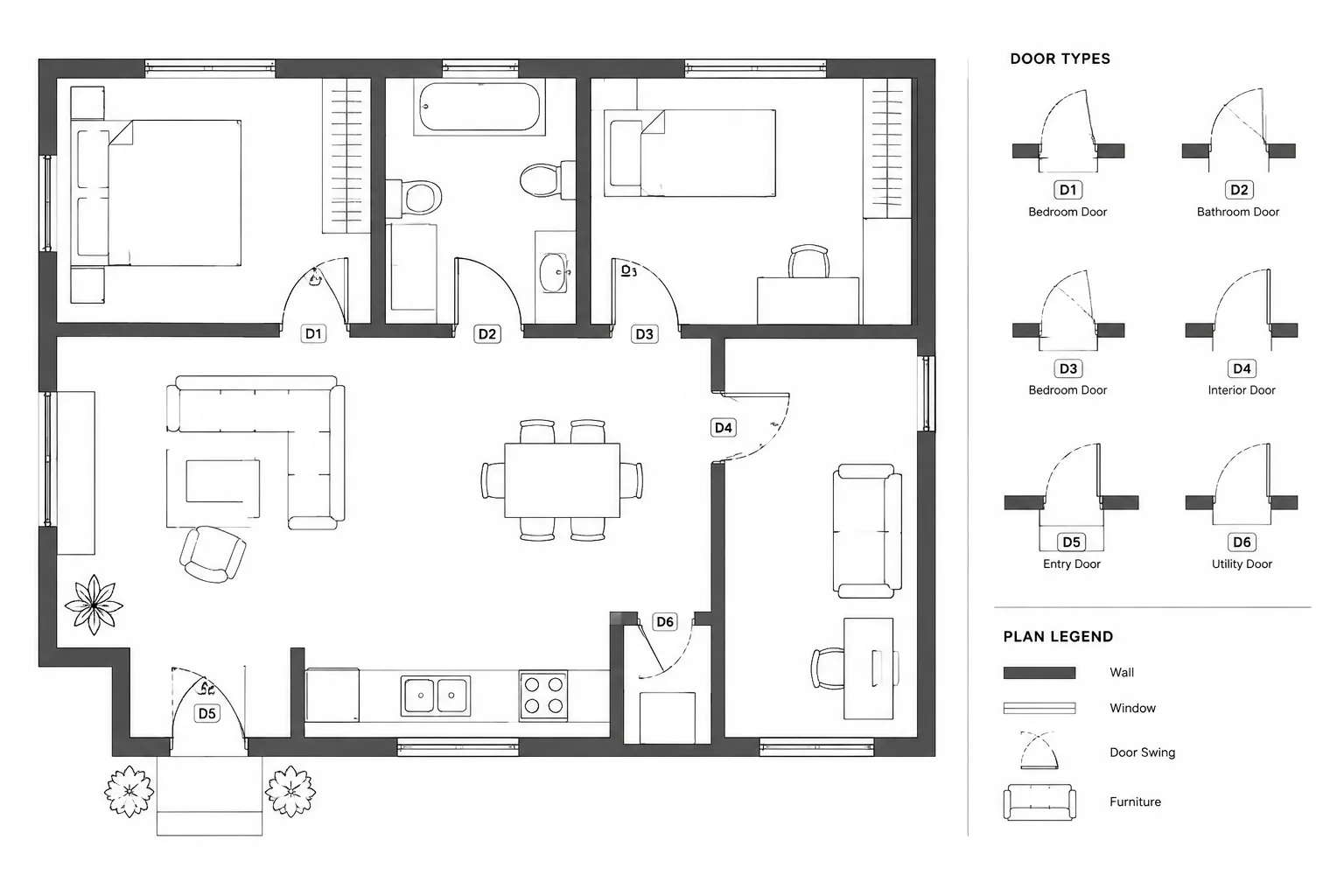
Door swings in architectural floor plans are both operating symbols and coordination tools. Their geometry helps readers interpret the hinge location, opening direction, and space used by the moving leaf, while the associated tag connects each opening to schedules and related documentation.
This guide explains how to construct, organize, and review door graphics in CAD. It also highlights the coordination checks needed when doors are inserted, mirrored, moved, replaced, or shown in multiple drawing views.
A door swing may look like a minor graphic element, but it communicates several important design decisions at once. It shows which side of an opening is hinged, the direction of operation, the approximate area occupied by the moving leaf, and the relationship between the door and nearby walls, fixtures, furniture, and circulation paths.
Incorrect door swings in architectural floor plans can cause coordination problems even when the wall opening itself is correct. A reversed swing may conflict with a cabinet, conceal a control, block access to a fixture, or disagree with the door schedule and hardware information. The goal of a reliable CAD workflow is therefore not simply to draw an arc. It is to treat every door as a coordinated assembly with a clear identity, location, orientation, and operation.
What a Door Swing Communicates
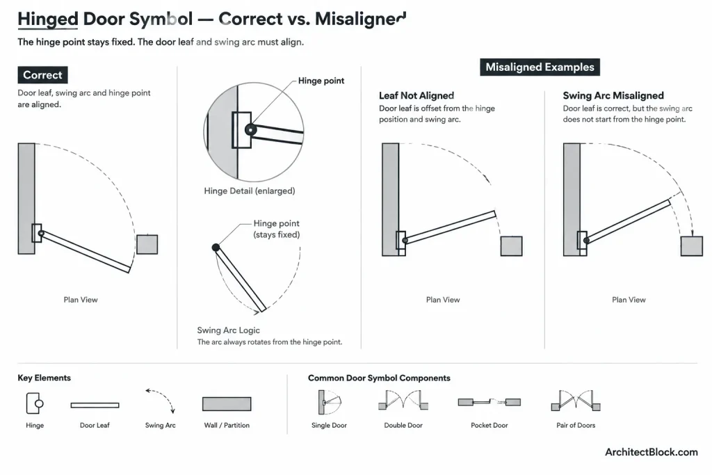
In a conventional floor plan, a hinged door is commonly represented by a leaf line extending from the hinge point and an arc indicating its movement. Together, these elements allow a reader to understand how the opening is intended to function.
A complete plan symbol may communicate:
- The location and width of the wall opening
- The hinge side of the active leaf
- Whether the door opens into or away from a room
- The relationship between the open leaf and adjacent construction
- Whether an opening contains one leaf, paired leaves, or another operating configuration
- The connection between the plan opening and its door identification tag
The swing arc is usually diagrammatic rather than a fabrication drawing of the hinge movement. It should remain geometrically consistent with the leaf and legible at the intended plotted scale.
Start with the Opening, Frame, and Leaf
A dependable door symbol should be based on coordinated geometry rather than an isolated arc placed over a wall. Begin by confirming the opening location and the wall faces. Then place the frame or jamb representation appropriate to the drawing scale and office graphic standard.
The hinge point should align with the intended pivot side of the frame. Draw or insert the leaf from that point in its open-plan position, and generate the swing arc from the same center. If the leaf and arc do not share a logical hinge point, the symbol may appear distorted or suggest the wrong opening width.
Keep the wall opening, jamb geometry, leaf, and swing visually related. Moving only one component during a revision is a common source of errors. A block-based door assembly can reduce this risk, but only if its geometry and parameters have been tested.
Understand Orientation Before Assigning Handing
Terms such as left-hand and right-hand door can be interpreted differently depending on viewpoint, swing direction, and hardware convention. Do not assign a handing label based only on how a symbol looks on the screen.
Instead, verify the door using a consistent project method:
- Identify the spaces on both sides of the opening.
- Determine which direction the leaf opens.
- Confirm the hinge side from the agreed reference viewpoint.
- Check whether hardware documentation uses the same terminology.
- Coordinate the result with the door schedule and hardware information.
If the project team has not established a handing convention, the plan geometry should remain unambiguous and the terminology should be clarified before issue. Mirroring a block can change the hinge side and may also affect attributes, tag orientation, hardware notes, or visibility settings.
Choose a Consistent CAD Construction Method
Individual linework
Lines and arcs are quick for one-off conditions and unusual openings. They also make local editing straightforward. However, loose geometry is easier to separate accidentally, and repeated doors may become inconsistent across a large plan.
Static blocks
A static block is useful when a project uses a controlled set of common door configurations. Separate blocks may be maintained for different orientations or leaf arrangements. The disadvantage is that a large collection can become difficult to manage if block names are unclear.
Configurable blocks
A carefully built configurable block can offer adjustable opening geometry, flipping controls, and visibility options. This may reduce the number of block definitions, but it also creates additional quality-control responsibilities. Test every allowed state, including mirrored orientations, attribute positions, plotted lineweights, and behavior after stretching.
Whichever method is used, avoid creating near-duplicate door blocks with vague names. A user should be able to distinguish between symbol configuration, nominal type reference, and project-specific door identity.
Organize Door Graphics by Function
Door components do not always need to share one layer. Separating information by function can provide better control across floor plans, reflected ceiling plans, demolition views, presentation plans, and consultant backgrounds.
A practical layer strategy may distinguish among:
- Door leaf and frame geometry
- Swing arcs or operating indicators
- Door identification tags
- Overhead or hidden door components
- Existing, removed, and new work
Use the project layer standard rather than introducing improvised names. Keep color, linetype, and lineweight controlled through the intended property workflow. Object-level overrides may produce a correct appearance in one view while causing inconsistent output elsewhere.
Coordinate the Full Swing Area
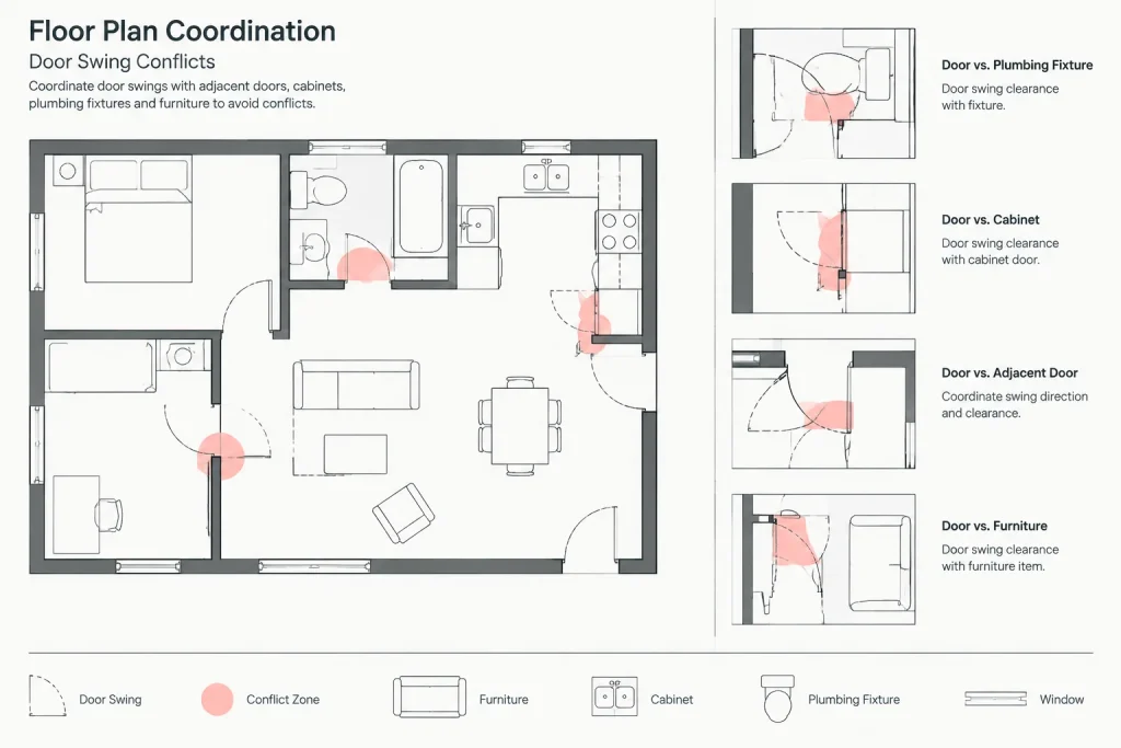
The swing arc is a useful visual warning, but coordination should not stop at whether the arc touches another line. Review the entire area occupied by the moving leaf and the likely use of the adjacent space.
Check door operation against:
- Adjacent doors and overlapping swing paths
- Fixed cabinets, countertops, and millwork projections
- Plumbing fixtures and bathroom accessories
- Furniture and equipment
- Columns, pilasters, and wall projections
- Floor level changes, ramps, and steps
- Controls, switches, panels, and access points shown by consultants
- Required maneuvering or clearance areas established for the project
A line intersection does not automatically prove that a condition is unacceptable, and a clear-looking plan does not prove compliance. Applicable codes, accessibility criteria, hardware requirements, and manufacturer information must be checked separately by the responsible project team.
Handle Common Door Configurations Carefully
Doors near inside corners
Confirm that the leaf can open as intended without the handle, frame, or door face conflicting with the adjoining wall. The plan should also leave enough graphic separation to make the hinge location readable.
Paired doors
Show both leaves and identify which leaf is active when that distinction matters to project documentation. Verify that the schedule, hardware information, and plan all describe the same arrangement. Avoid assuming that two leaves are equal merely because the opening appears symmetrical.
Double-acting doors
Use an office-approved symbol that clearly distinguishes double action from an ordinary single-direction swing. The plan representation should not leave readers guessing whether multiple arcs indicate alternate design options or actual operation.
Doors in tight vestibules
Review the doors together rather than as separate objects. Conflicts may occur between leaves, handles, required clearances, or the sequence in which users pass through the space.
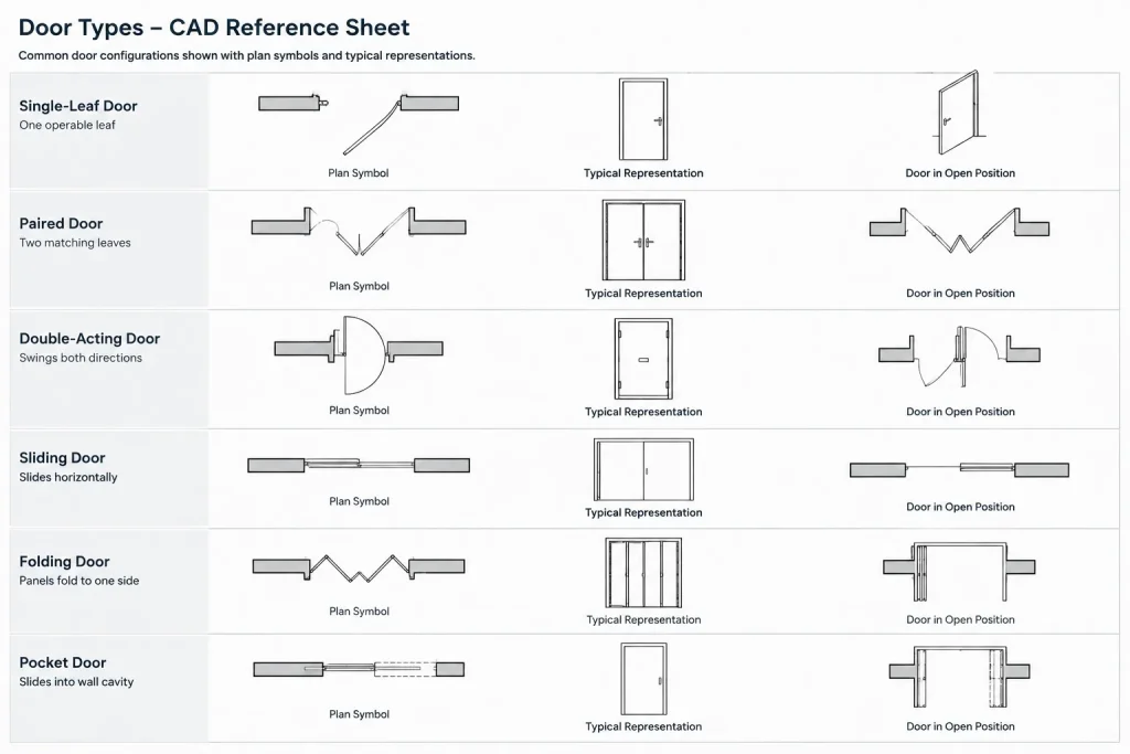
Sliding, folding, and pocket doors
Do not represent these with a standard hinged-door swing. Show the operating direction and stored position using a clear symbol appropriate to the door type. Coordinate concealed pockets, tracks, and adjacent wall contents where relevant.
Keep Door Tags Separate from Swing Geometry
The door tag identifies the opening; it should not become part of the moving leaf or swing arc. Keeping tags logically separate makes it easier to reposition annotation without altering the modeled opening.
Place tags where they are readable and clearly associated with the correct door. Avoid placing a tag directly over dense wall geometry, room text, dimensions, or another door swing. If a doorway is moved, verify that its tag moves with the intended opening and that the identifier still matches the schedule.
Review Door Swings at Multiple Scales
A door symbol that looks clear while zoomed in may become muddy or disappear on the plotted sheet. Review the plan at its intended output scale and inspect any enlarged plans where the same opening appears.
At smaller scales, prioritize a clear hinge point, leaf direction, and swing arc. At larger scales, frames, jambs, adjacent clearances, and hardware-related geometry may require more development. The same opening should not appear to operate differently between the overall plan and an enlarged view.
Door Swing Quality-Control Checklist
| Check | What to verify |
|---|---|
| Opening | The door is located in the correct wall and aligns with the intended opening. |
| Hinge point | The leaf and arc originate from a consistent pivot location. |
| Swing direction | The door opens toward the intended space and agrees with design requirements. |
| Configuration | Single, paired, sliding, folding, pocket, or double-acting operation is shown correctly. |
| Conflicts | The moving leaf has been reviewed against construction, fixtures, furniture, and other doors. |
| Identification | The plan tag matches the door schedule and related documentation. |
| Handing | Any handing designation follows the project’s agreed reference convention. |
| Graphics | Layers, lineweights, linetypes, and plot visibility are consistent. |
| Related views | Overall plans, enlarged plans, elevations, and details describe the same opening. |
| Revision status | Moved, removed, or replaced doors have been updated in tags, schedules, notes, and backgrounds. |
A Better Revision Workflow
When a door changes, treat the edit as a coordinated revision rather than a local graphic adjustment. Update the opening and swing first, then review the tag, schedule entry, hardware information, dimensions, wall construction, elevations, and consultant backgrounds.
After moving or flipping a door, search the surrounding area for former geometry, disconnected arcs, duplicate tags, and dimensions that still reference the previous jamb location. Plot or preview the affected sheet before considering the change complete.
Clear door swings in architectural floor plans result from disciplined coordination. Consistent geometry, controlled blocks, deliberate layers, and repeated checks help the plan communicate operation without ambiguity—and reduce the chance that a small drafting symbol becomes a larger field or documentation problem.
Use the Door as a Coordination Point
A productive review begins with the door itself and then expands into the surrounding documentation. Confirm the opening, frame, hinge point, leaf, and operating indicator before checking nearby objects. Next, compare the plan symbol with its tag, schedule entry, hardware information, enlarged views, elevations, and consultant backgrounds.
This sequence helps distinguish a drafting defect from a broader design conflict. A disconnected arc is primarily a graphic problem, while a leaf colliding with fixed construction may require a design response. A correctly drawn symbol can still be inconsistent with the schedule, and a visually clear plan does not by itself establish code or accessibility compliance.
Make Revisions Traceable
When a door is changed, review every place where its location or identity is referenced. Preserve a clear relationship between the opening and its annotation, and remove obsolete geometry rather than leaving overlapping blocks or abandoned swing arcs in the file.
Before issuing the drawing, inspect the affected area at the intended plotted appearance. Confirm that linework remains readable, tags identify the correct openings, and related views communicate the same operation. Project-specific code, accessibility, hardware, and manufacturer requirements should be verified by the responsible design team.
Frequently Asked Questions
What does a door swing show on a floor plan?
It indicates the hinge side, the direction in which the leaf operates, and the approximate area occupied as the door opens. Together with the frame and tag, it helps identify how the opening relates to nearby spaces and objects.
Why should the swing arc and door leaf share the same hinge point?
A common pivot keeps the symbol geometrically coherent. If the arc and leaf originate from different locations, the drawing may imply an incorrect opening or create a distorted operating path.
Can a door block be mirrored to change its handing?
Mirroring may change the hinge side, but it can also affect attributes, tags, notes, and configurable block behavior. Review the complete block state and confirm the result against the project’s handing convention and related documentation.
Should the door tag be included in the swing block?
The tag should remain logically independent from the moving leaf and arc. This allows annotation to be repositioned for readability without changing the opening geometry, while still maintaining a clear association with the correct door.
How should sliding or pocket doors appear in plan?
They should use symbols that communicate their actual operating direction and stored position rather than a hinged-door arc. Concealed pockets, tracks, and nearby wall contents should be coordinated where they affect the drawing.
Does a clear swing arc prove that a door complies with project requirements?
No. The arc is a diagrammatic coordination aid. Code, accessibility, hardware, clearance, and manufacturer requirements require separate review by the responsible project team.