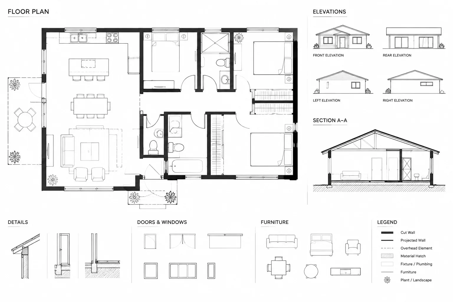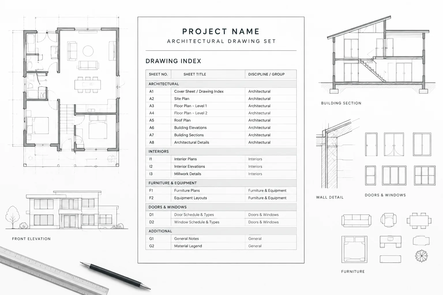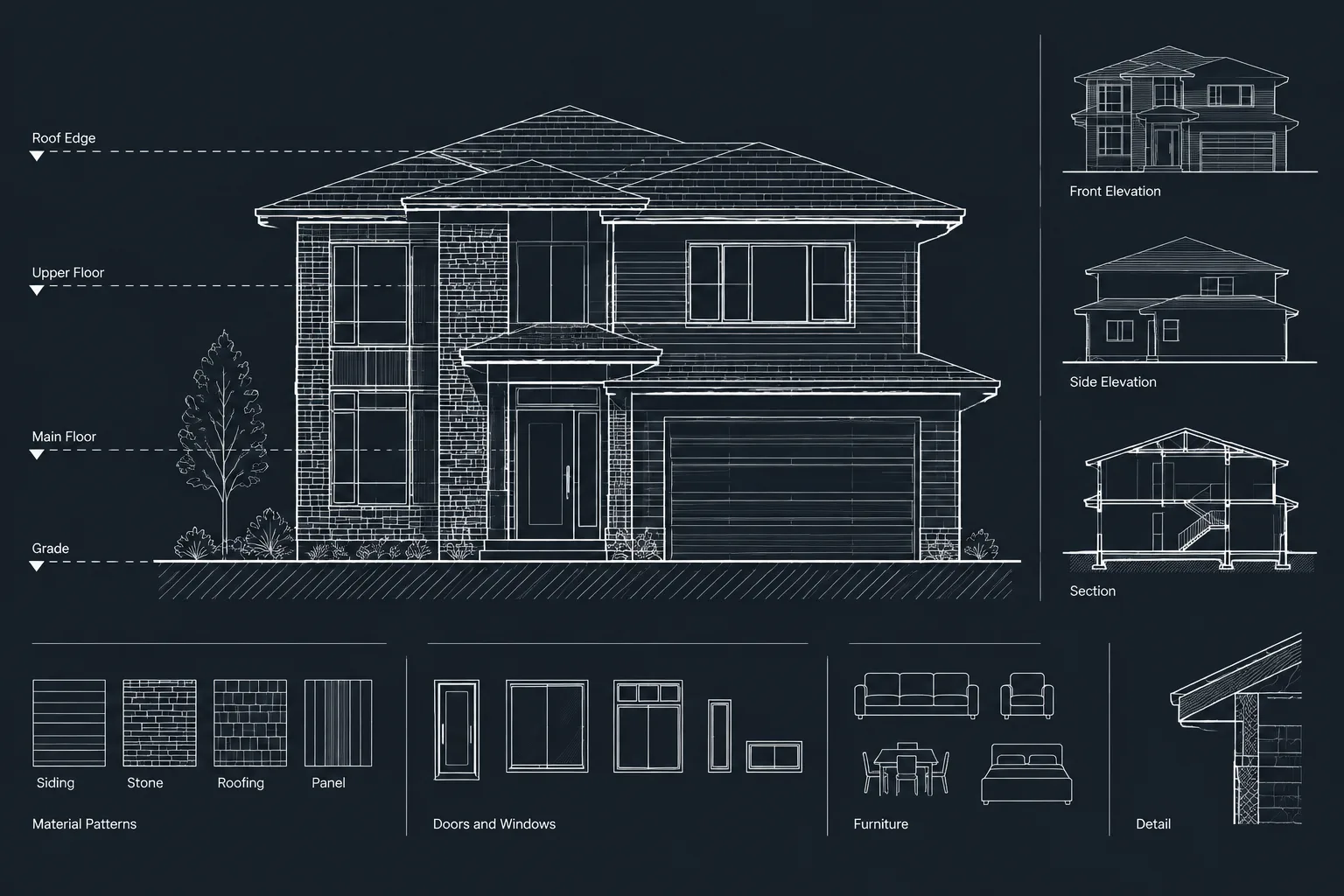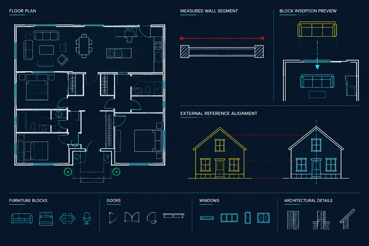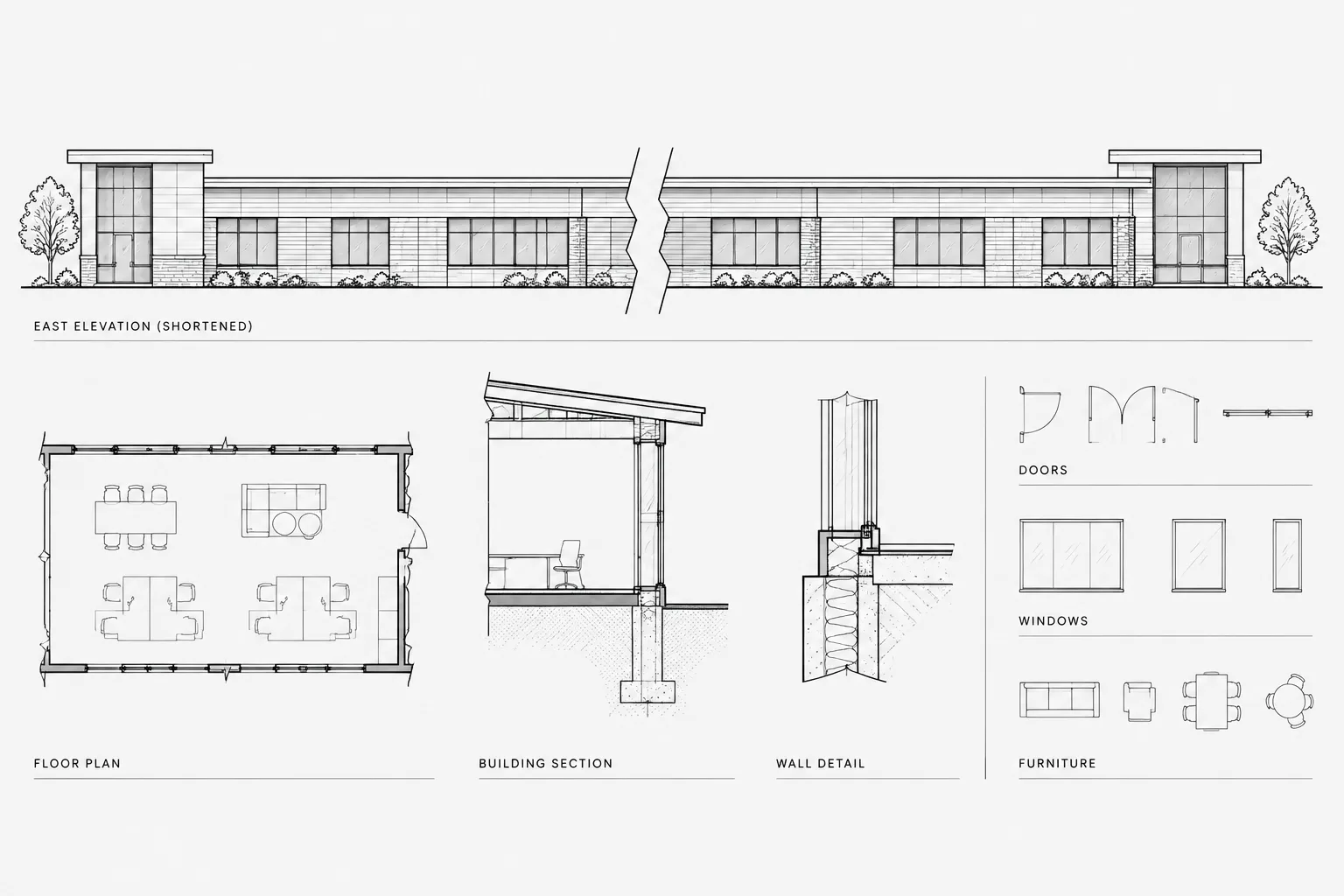
Break lines in architectural CAD help fit long, tall, or repetitive subjects into a readable drawing area without suggesting that the represented construction physically ends. Their effectiveness depends on more than the symbol itself: the source geometry, visible endpoints, hatches, dimensions, leaders, and plotted appearance must all support the same interpretation.
This guide explains how to distinguish break lines from other drawing boundaries, choose an appropriate graphic treatment, preserve coordinated geometry, and review shortened views before issue. The goal is a compact presentation that remains clear to anyone reading the sheet.
Break lines allow a drafter to omit part of an object or view while showing that the drawing continues beyond the displayed geometry. They are useful for long building elements, repetitive assemblies, partial elevations, wall sections, site features, and details that would otherwise consume too much sheet space.
Although a break line may look like a simple drafting symbol, it carries an important message: part of the subject has been intentionally removed from the view. If the symbol is unclear, inconsistently applied, or confused with a match line, the drawing can become misleading. A reliable workflow therefore addresses both the graphic symbol and the geometry behind it.
What a break line communicates
A break line indicates that a continuous object or view has been shortened, interrupted, or shown only in part. The omitted portion is not necessarily demolished, separated, or physically discontinuous. It is simply not displayed in that view.
Common architectural uses include:
- Shortening a long wall, railing, counter, curb, or linear site element.
- Removing a repetitive middle portion from an elevation or section.
- Limiting a partial plan, elevation, or detail to the area relevant to the drawing.
- Showing the upper and lower portions of a tall assembly without drawing its entire height.
- Ending a detail where adjacent construction continues but is outside the detail’s purpose.
The break should not conceal information needed to understand dimensions, alignment, connections, transitions, or construction scope. If the omitted portion contains a change in material, level, profile, or configuration, a shortened view may be inappropriate.
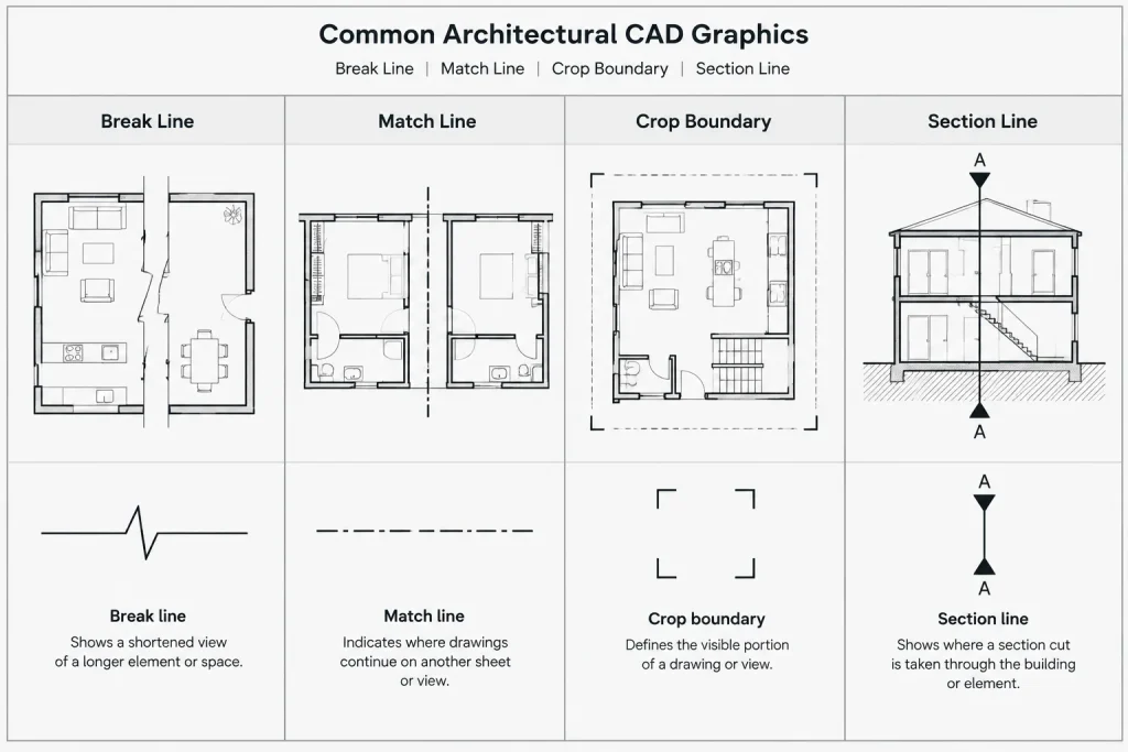
Break line, match line, crop boundary, or section line?
Several architectural graphics can appear to divide a drawing, but they serve different purposes.
| Graphic | Primary purpose | Typical coordination requirement |
|---|---|---|
| Break line | Indicates that part of an object or view has been omitted. | Confirm that the shortened representation does not distort design information. |
| Match line | Divides a continuous plan or view between separate drawing areas or sheets. | Provide a clear continuation reference and coordinate geometry on both sides. |
| Crop boundary | Controls or describes the visible extent of a view. | Confirm that tags, dimensions, and relevant context remain visible. |
| Section line | Identifies the location and viewing direction of a section cut. | Coordinate the callout with the referenced section or sheet. |
| Property or limit line | Represents an actual boundary, agreement, or scope limit. | Use the correct line convention and supporting annotation. |
A break line should not be used as a substitute for a match line when a drawing continues elsewhere. Likewise, a viewport edge alone may crop a view, but it does not always explain that a physical object has been intentionally shortened within the drawing.
Choose a break style that fits the subject
Architectural drawings commonly use irregular freehand-style breaks, zigzag breaks, or compact break symbols crossing a narrow element. The selected style should be recognizable at the plotted scale and compatible with the office’s graphic conventions.
Irregular break boundaries
An irregular or freehand-style boundary works well at the edge of a partial plan, elevation, section, or detail. Its uneven profile distinguishes it from a physical straight edge. It is especially useful when several layers or components continue beyond the displayed area.
Compact breaks across linear elements
A compact break symbol can shorten a railing, wall, pipe chase, counter, or other narrow linear object. The symbol should cross the affected geometry clearly enough to show which elements continue. Avoid placing it where it could be mistaken for a joint, seam, hinge, or material transition.
Paired breaks in shortened views
When the middle of a long or tall subject is omitted, paired breaks can define the removed region. Both sides must remain aligned so that the reader understands they represent the same continuous assembly. Any dimensions crossing the omitted region require special attention because the drawn length no longer represents the real length.
A practical CAD workflow
Start with complete, coordinated geometry
Whenever practical, draft the object at its actual extent before creating a shortened presentation. Complete geometry is easier to coordinate with plans, elevations, sections, grids, and consultant backgrounds. It also reduces the risk that a display shortcut will alter the design model.
If a dedicated detail drawing is intentionally schematic, record that decision in the drawing organization. Do not allow shortened geometry to be reused later as though it were a complete building element.
Decide whether the break belongs in geometry or presentation
A break can be created by trimming copied linework in a dedicated view, masking part of the view, clipping a reference, or limiting a viewport. These methods are not interchangeable.
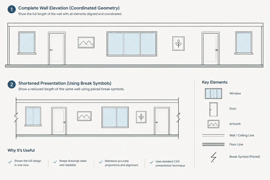
- Trimmed view geometry: Appropriate for an independently drafted detail or elevation, but changes must be coordinated manually.
- Masking: Preserves geometry behind the mask, although draw order and plotting must be checked carefully.
- Reference clipping: Useful for controlling the displayed portion of an external reference without editing the source file.
- Viewport cropping: Useful for sheet composition, but the crop alone may not communicate a break within an object.
Use the method that preserves the project’s source geometry and makes future editing understandable. Avoid destructive trimming in a shared base plan merely to improve one sheet.
Place the symbol on a controlled layer
Break symbols should be assigned to an intentional annotation or view-graphics layer rather than mixed into wall, furniture, or structural geometry. A controlled layer makes it easier to manage visibility, plotting, and viewport-specific presentation.
The symbol’s properties should follow the project’s layer and plotting system. Review its plotted weight relative to the cut geometry and secondary lines around it. A break should be visible without overpowering the subject.
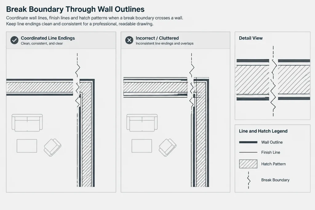
Clean the visible endpoints
Where a break crosses multiple lines, decide which lines stop at the break and which continue behind it. Random line endings create visual noise and may imply separate components. Use trimming, masking, or draw order consistently so the break reads as one deliberate boundary.
Hatches require particular care. A hatch that continues through an omitted area can undermine the break, while a poorly edited hatch may leave slivers or unexpected boundaries. Inspect both the CAD view and the plotted output.
Protect dimensions and annotations
Do not infer a real length from shortened graphic geometry. If an overall dimension is necessary, it should report verified project geometry rather than the apparent distance between the displayed endpoints. Avoid dimensioning across a removed region unless the intended value and extension-line references are unambiguous.
Keep tags, keynotes, leaders, and material labels on the visible side of the break. A leader disappearing into an omitted area suggests that referenced information is missing. If important annotation belongs beyond the boundary, expand the view or provide another referenced drawing.
Building a reusable break-line block
A reusable block can improve consistency, especially for compact break symbols. Build it with a logical insertion point and neutral base orientation. Test rotation, mirroring, scaling, and plotting before adding it to a shared library.
A good block should be simple enough to edit and should not contain unrelated layers, text styles, hidden attributes, or distant stray objects. Keep annotation behavior consistent with the rest of the project. If separate symbols are needed for different applications, use clear names rather than forcing one complicated block to handle every condition.
Freeform partial-view boundaries may be better drawn as controlled polylines because their shape often depends on the surrounding geometry. Consistency does not require every irregular break to be identical; it requires the graphic language to remain recognizable.
Common mistakes to avoid
- Using a break to hide unresolved coordination: A break should save drawing space, not conceal an uncertain connection or transition.
- Breaking only some related lines: Walls, finishes, edges, hatches, and overhead elements should tell a coherent continuation story.
- Confusing a break with a physical joint: Keep the symbol visually distinct from expansion joints, control joints, seams, and material boundaries.
- Editing the shared base unnecessarily: Sheet-specific presentation changes should not damage coordinated source geometry.
- Allowing annotation to cross the omitted area: Dimensions and leaders can make a shortened view appear complete when it is not.
- Relying on model-space appearance alone: A break that looks clear while drafting may become weak, heavy, or cluttered at the final plot scale.
Quality-control checks before plotting
Review every shortened or partial view in its final sheet context. Confirm that the break is visible, the continuation is obvious, and no essential information has been omitted. Check that aligned components remain aligned on both sides and that the drawing does not imply a false overall proportion.
Also compare the view with its source plan, elevation, section, or detail. Verify that dimensions come from coordinated geometry, that tags reference visible objects, and that hatches and masks plot correctly. If a reader would need to guess what happens within the omitted portion, the view should be expanded or supplemented with another drawing.
Used carefully, break lines make architectural drawings more compact without sacrificing meaning. The strongest workflow preserves complete source geometry, treats the break as a presentation device, and verifies that every omitted portion is genuinely unnecessary to the view’s purpose.
A decision framework for using a break
Before shortening a view, identify what the reader must understand from it. A break is most effective when the omitted area is continuous, predictable, and unnecessary to the drawing’s immediate purpose. If that area contains a connection, change, offset, opening, transition, or annotation needed for coordination, show more of the subject or provide a separate referenced view.
Separate design information from sheet presentation
Complete source geometry should remain the dependable basis for coordination whenever practical. The shortened view can then be treated as a presentation condition rather than a change to the represented building element. This distinction helps prevent cropped or trimmed graphics from being mistaken for the actual extent of the work.
Review the complete graphic system
A convincing break affects more than object outlines. Cut lines, surface lines, hatches, overhead graphics, dimensions, tags, and leaders should all respond consistently to the omitted area. If one category continues while another stops without a clear reason, the break may appear accidental or may resemble a physical joint.
Check the view from the reader’s perspective
Someone reviewing the sheet should be able to recognize what continues, understand that information was intentionally omitted, and avoid reading the displayed length as the actual length. If the interpretation depends on knowledge available only to the drafter, the view needs clearer graphics, annotation, or additional context.
Coordination and handoff considerations
Shortened views should remain understandable when another CAD user opens, revises, or plots the file. Use recognizable layer organization, keep reusable symbols free of unrelated content, and avoid presentation edits that obscure the coordinated source. Where masking or clipping is used, review draw order and visibility after references or surrounding geometry change.
During quality control, compare the partial view with the complete source rather than checking it in isolation. This reveals missing transitions, misaligned components, unsupported dimensions, and annotations that point into hidden areas. It also confirms that the break saves space without changing the intended meaning of the drawing.
Frequently asked questions
Does a break line mean that the building element physically stops?
No. A break line normally indicates that part of a continuous object or view has been intentionally omitted from the drawing. A physical termination, joint, or separation should be represented with the appropriate geometry and annotation.
When should a match line be used instead of a break line?
Use a match line when a continuous drawing area is divided and continues in another view or sheet area. Use a break line when part of the represented subject is omitted rather than transferred to a coordinated continuation view.
Should the original CAD geometry be trimmed to create a shortened view?
Not automatically. Destructive trimming can damage geometry used by other views or team members. When practical, retain the complete coordinated source and create the shortened appearance through a dedicated view, controlled masking, reference clipping, or sheet presentation method.
Can a dimension cross a break line?
It can only be reliable when the value comes from verified project geometry and the referenced points are unambiguous. The apparent distance in a shortened view must not be treated as the actual overall length.
Why can a break line look correct in CAD but fail on the sheet?
Plot scale, lineweight, draw order, masking, hatches, and nearby annotation can change how the symbol reads. Review the final sheet presentation rather than relying only on the drafting view.
Should every break use the same symbol?
Consistency is important, but the graphic should also suit the subject. A compact symbol may work for a narrow linear element, while an irregular boundary may communicate the edge of a partial plan, elevation, section, or detail more clearly.