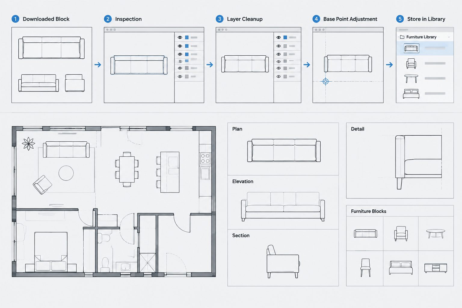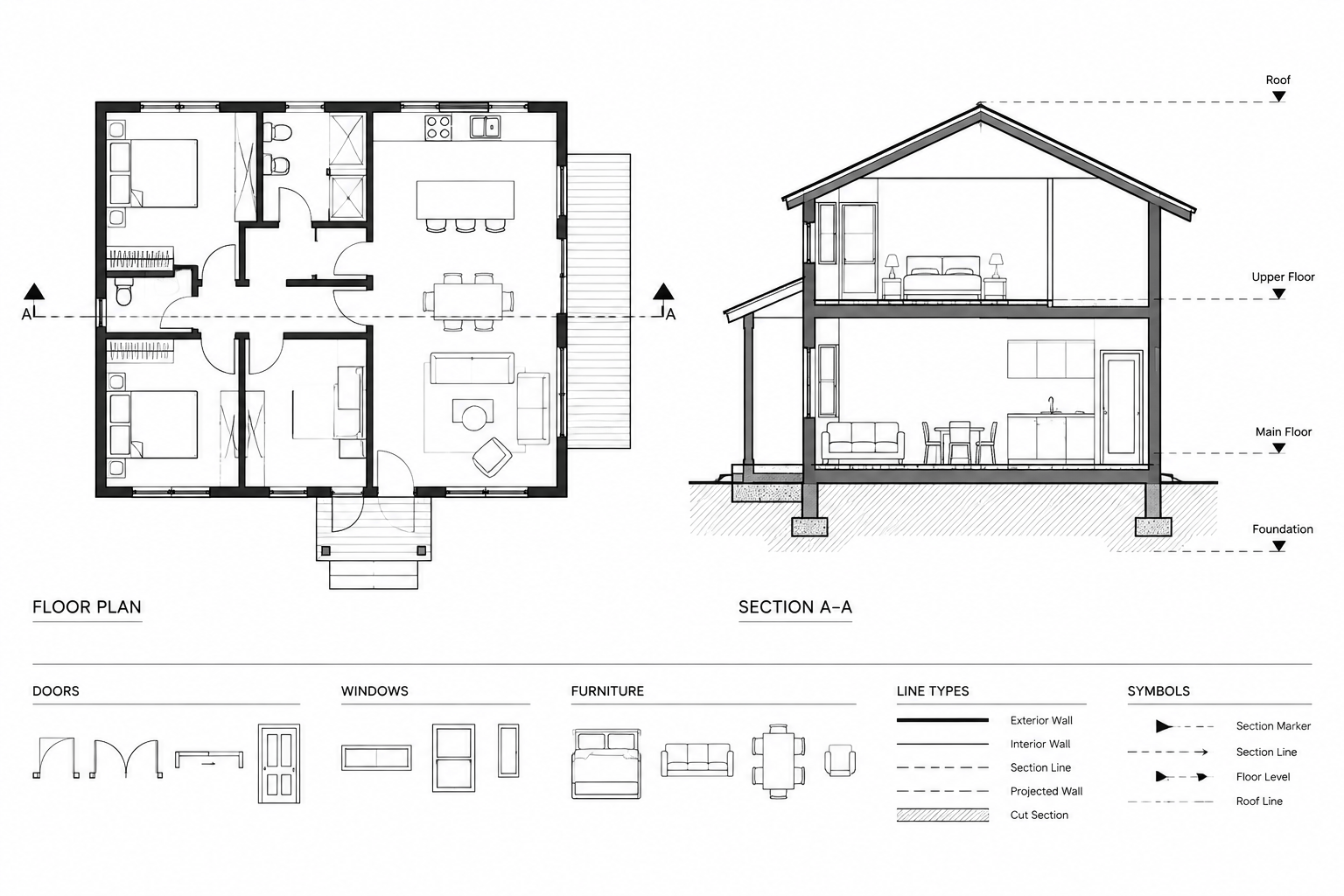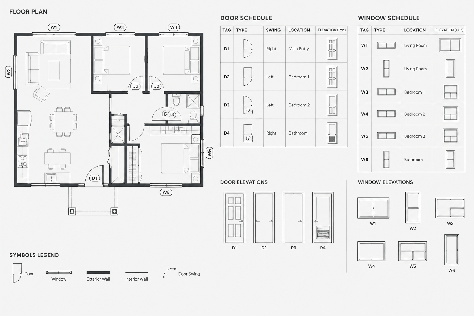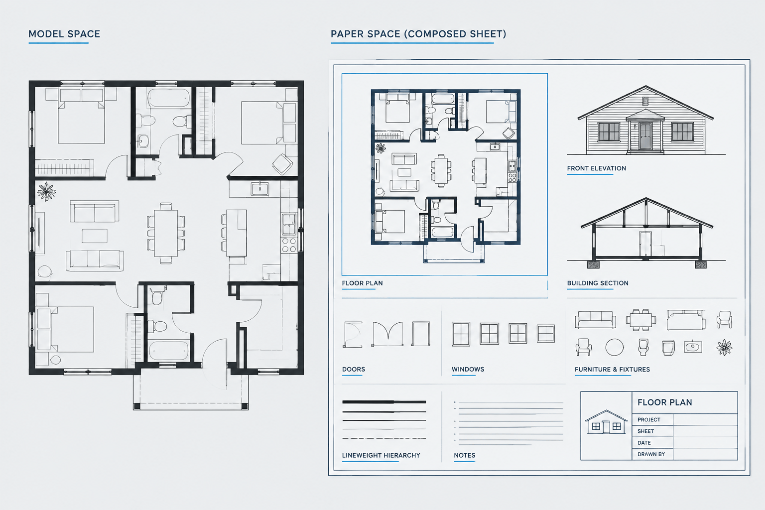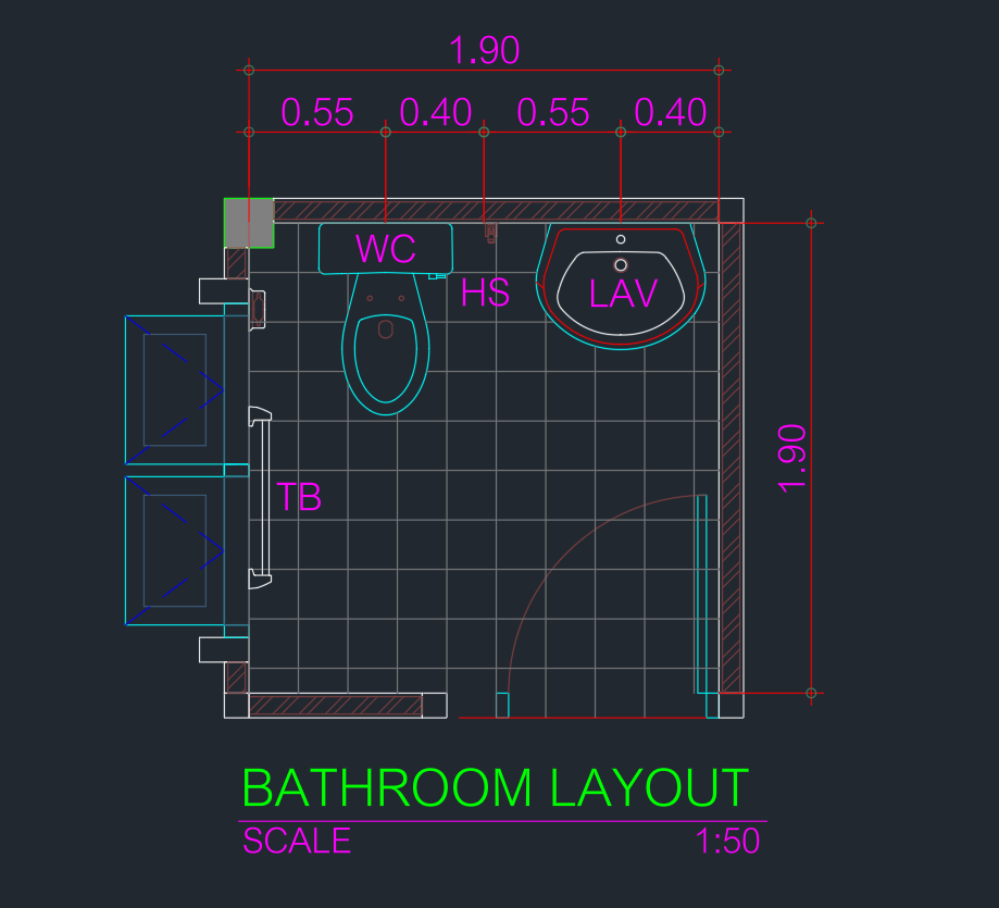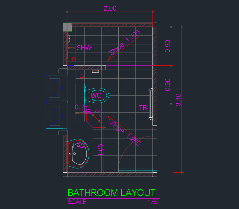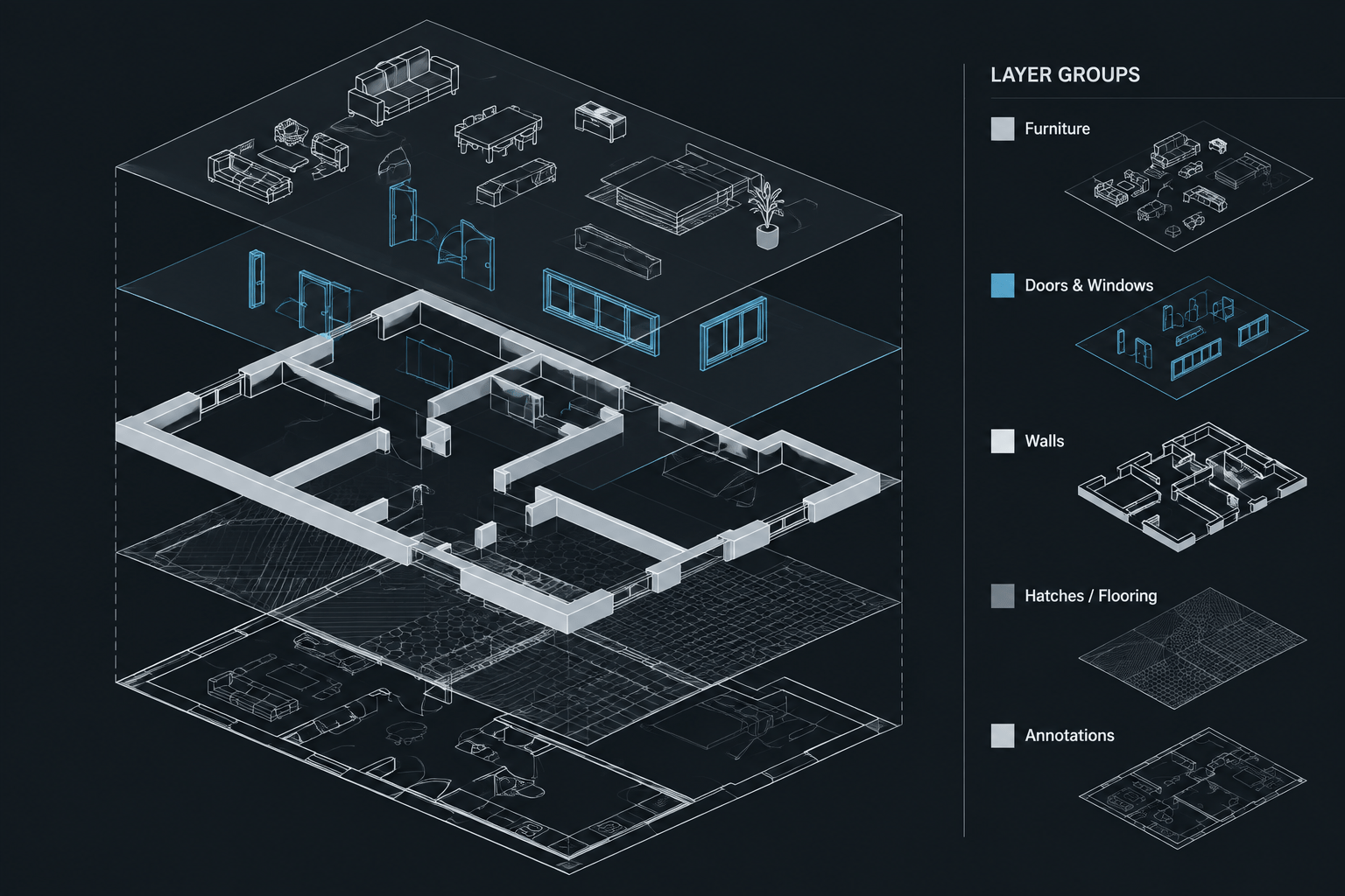
A well-organized architectural drawing is easier to edit, review, plot, and share. Layers provide the basic structure that makes this possible. They separate walls, doors, fixtures, dimensions, notes, reference files, and other drawing information so each category can be controlled without affecting unrelated objects.
Good architectural CAD layer organization is not simply a matter of creating a long list of names. The real goal is to make drawing content predictable. A drafter opening the file should be able to identify where an object belongs, understand why a layer exists, and control its visibility without searching through duplicate or ambiguous options.
The following workflow can be adapted to office standards, consultant requirements, and project-specific needs. It is a practical starting point rather than a substitute for an established CAD manual or a required project standard.
What an Architectural Layer Should Control
A layer can control several properties shared by the objects assigned to it. Depending on the CAD setup, these may include visibility, color, linetype, lineweight, transparency, plotting behavior, and whether objects can be selected or edited.
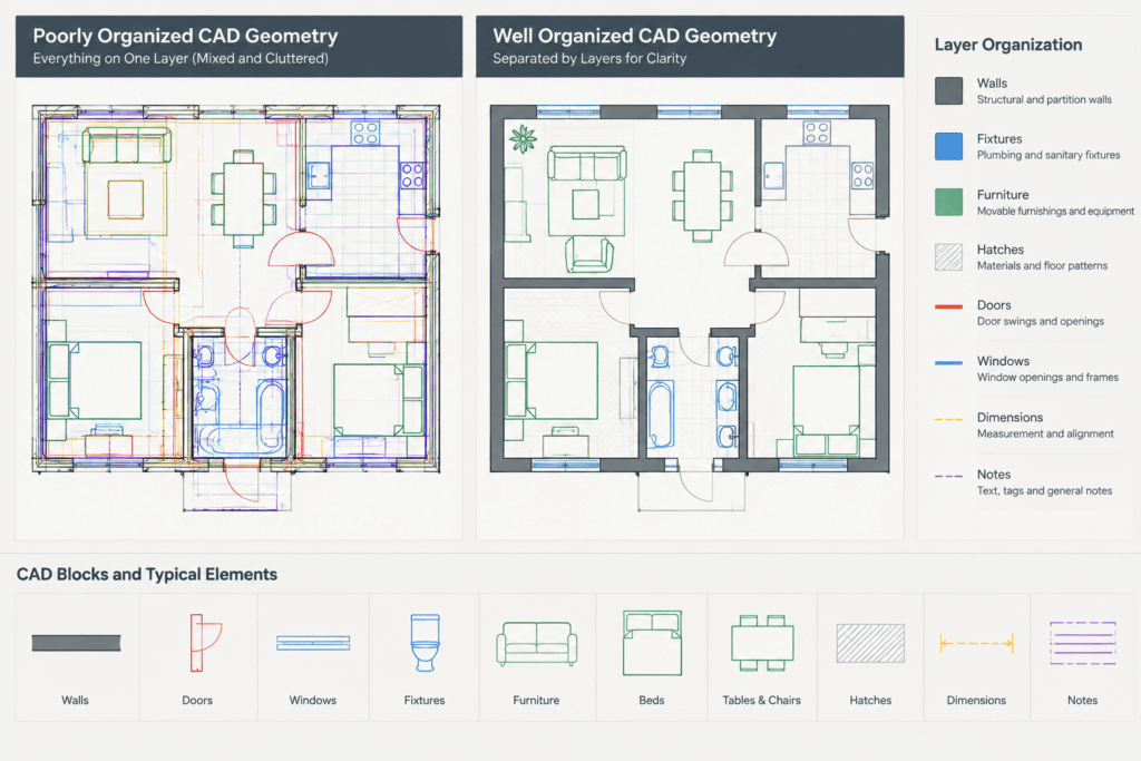
Layers work best when they represent meaningful drawing categories. A wall line and a room label may appear in the same plan, but they serve different purposes and should normally be controlled independently. Separating them allows the team to prepare different views from the same model-space information.
Useful architectural categories commonly include:
- Building elements such as walls, doors, windows, stairs, roofs, and ceilings
- Fixed fixtures, casework, plumbing fixtures, and built-in equipment
- Loose furniture and movable equipment
- Dimensions, notes, room names, tags, and reference symbols
- Overhead, hidden, or beyond-view elements
- Hatches, poche, fills, and material indications
- Grids, levels, property information, and layout guides
- External references and consultant backgrounds
- Nonplotting construction or coordination information
Build Layer Names Around a Consistent Logic
Layer names should communicate their purpose without becoming unnecessarily complicated. A simple naming structure can begin with a discipline or drawing category, followed by an element and an optional modifier.
| Naming component | Purpose | Example concept |
|---|---|---|
| Discipline or group | Identifies the broad source of the information | Architectural, structural, site, or interiors |
| Element | Identifies the object category | Walls, doors, windows, furniture, or text |
| Modifier | Separates a special condition or graphic role | Existing, demolished, overhead, hidden, or annotation |
For example, an office might use a consistent sequence that distinguishes architectural walls from architectural wall hatches and overhead wall information. The exact abbreviations matter less than consistent application. Avoid creating several layers that mean nearly the same thing, such as separate variations of “door,” “doors,” and “door new.”
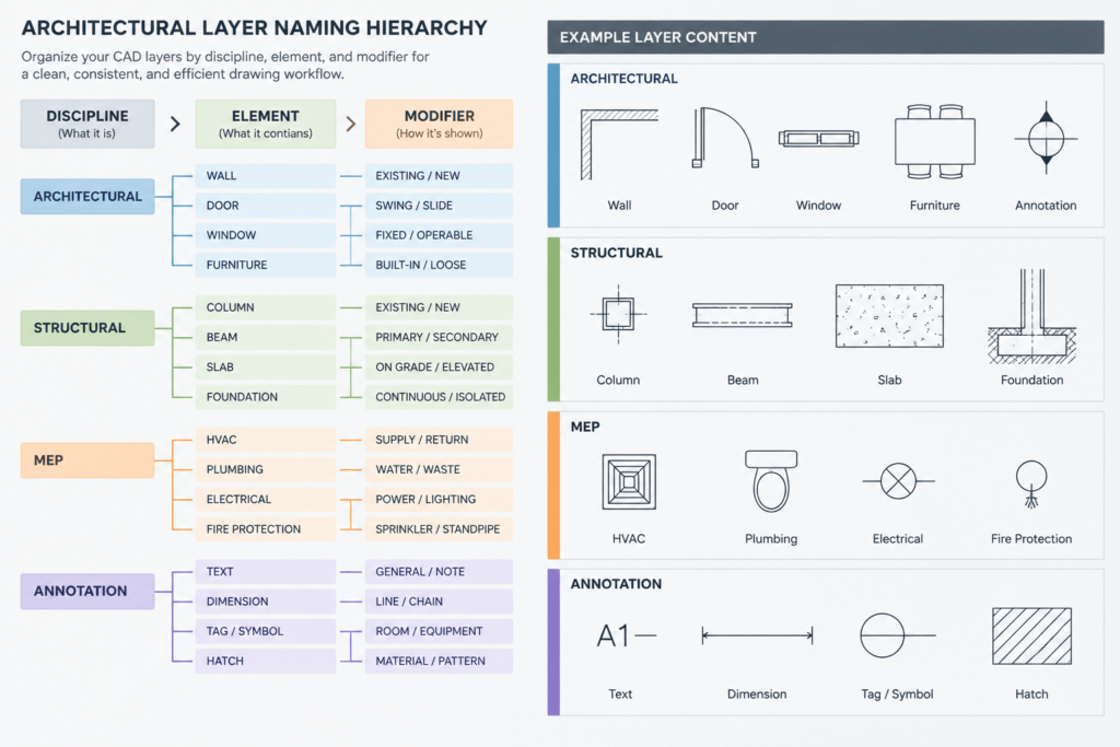
Before introducing a new layer, check whether an existing layer already serves the intended function. If it does not, create a name that follows the same structure as the rest of the file.
Separate Objects by Function, Not by Convenience
One of the most common drafting problems occurs when objects are placed on whichever layer happens to be current. This may not be obvious while drawing, but it becomes disruptive when a layer is frozen, locked, or given a different plotting property.
Classify an object by what it represents. A door tag belongs with annotation or identification information, not necessarily on the same layer as the door geometry. A countertop outline may belong with casework, while an appliance symbol may require separate control as equipment. A floor hatch should not automatically share a layer with the floor boundary.
Functional separation is especially helpful when preparing reflected ceiling plans, furniture plans, enlarged plans, presentation drawings, or demolition views. Each view can display the required information without forcing the drafter to erase, duplicate, or manually hide individual objects.
Use Object Properties By Layer
Whenever practical, assign object color, linetype, lineweight, and plotting behavior through the layer rather than overriding each object individually. By-layer properties make graphic changes faster and easier to audit.
If wall outlines need a different plotted emphasis, a layer-level change can update all correctly assigned wall objects. If some wall lines contain individual property overrides, those lines may continue to plot differently and become difficult to diagnose.
Individual overrides can be useful for a deliberate exception, but they should not become the normal method of controlling drawing graphics. When an exception is required, confirm that it is intentional and understandable to another user.
Plan for Drawing Views and Plotting
A layer list should support the actual sheets and views the project requires. Before drafting extensively, consider which information must appear in floor plans, ceiling plans, elevations, sections, schedules, details, and presentation drawings.
Elements that need independent visibility should generally not be combined. Common examples include:
- Overhead cabinets versus base cabinets
- Elements cut in section versus elements seen beyond
- Existing construction versus proposed work
- Demolition information versus new construction
- Furniture versus fixed casework
- Room names versus general notes
- Reference grids versus temporary layout lines
Plot-test the file early. Screen color alone does not confirm that the final drawing will have a clear graphic hierarchy. Review lineweights, hatches, hidden lines, text, and symbols at the intended plotted scale. The result should remain legible whether the drawing is printed or reviewed digitally.
Keep Annotation Layers Distinct
Dimensions and notes require a different kind of control from model geometry. Separating annotation categories helps prevent crowded views and supports discipline-specific or sheet-specific presentation.
A practical annotation structure may distinguish among dimensions, general notes, room information, door and window identifiers, section references, elevation references, revision information, and match lines. Not every project needs a separate layer for every symbol. Create distinctions only when they improve visibility control, coordination, or plotting.
Annotation should also be checked for ownership. Notes placed directly in a referenced background can be difficult to manage when the background is updated. Project teams should decide whether annotations belong in the source file, the sheet file, or another coordinated drawing file.
Manage External References Deliberately
External references can keep plans, consultant backgrounds, and sheet compositions coordinated without copying the same geometry into multiple files. However, references can also make the layer list more difficult to navigate because referenced layers appear alongside layers created in the current drawing.
Use clear reference file names and attach each background for a defined purpose. Place reference instances on dedicated host layers when that approach fits the project workflow. This provides a convenient way to control the entire reference while preserving access to its internal layers.
Avoid editing consultant information merely to make it resemble the architectural file. Instead, use reference display controls where appropriate and document any coordination issue that requires correction by the source author.
Create Nonplotting Layers for Drafting Aids
Temporary guides, study lines, viewport setup information, coordination notes, and construction geometry should not be mixed with finished architectural objects. Dedicated nonplotting layers make these aids available during drafting while keeping them out of issued drawings.
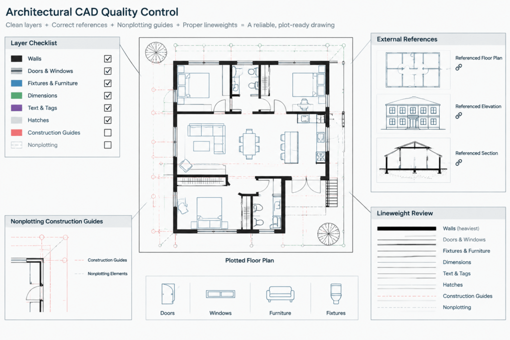
Do not assume that a layer will remain hidden or nonplotting merely because it appears that way on screen. Confirm its settings and inspect a plot preview. Remove obsolete working geometry before file delivery when it no longer provides useful project information.
Audit the Drawing Before Sharing It
Layer cleanup is most effective when performed throughout the project rather than only before submission. A short review can catch misplaced objects, unused layers, unexplained overrides, and accidental content.
Practical layer review checklist
- Confirm that major building elements are assigned to the intended layers.
- Look for objects placed on default or temporary layers without a clear reason.
- Check whether duplicate layer names represent the same function.
- Review individual color, linetype, and lineweight overrides.
- Verify that nonplotting information does not appear in plot preview.
- Confirm that required referenced drawings are attached and can be located.
- Check that hidden, frozen, or locked layers are intentionally controlled.
- Remove abandoned studies and redundant content when project procedures allow.
- Open representative sheet views and inspect the complete graphic hierarchy.
Avoid Overbuilding the Layer List
More layers do not automatically create a better-organized drawing. Excessive separation can slow navigation and increase the chance of assigning objects incorrectly. A layer should exist because it provides meaningful control, communicates ownership, or supports a drawing output.
For a small interior plan, a compact layer structure may be sufficient. A multidisciplinary building project may require more detailed categories. The appropriate level of complexity depends on the drawing set, team, deliverables, and required coordination.
Make the System Easy to Reuse
Once a reliable structure has been developed, incorporate it into approved drawing templates and office setup files. Include only layers that are genuinely useful at the start of most projects. Specialized layers can be added when the work requires them.
Document the naming logic in plain language so new team members can follow it without memorizing an unexplained abbreviation list. Consistency is maintained more effectively when users understand the reason behind the system.
Architectural CAD layer organization should ultimately reduce friction. A successful layer structure makes objects easier to find, drawings easier to plot, and files easier for another person to continue. It supports the drawing rather than becoming a separate administrative task.