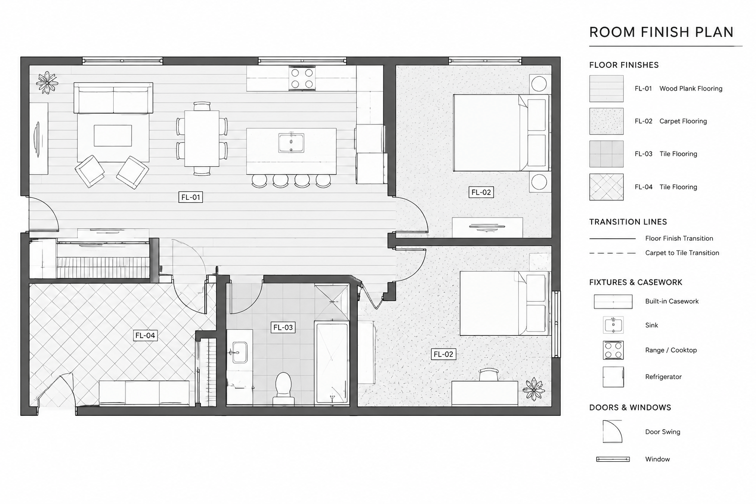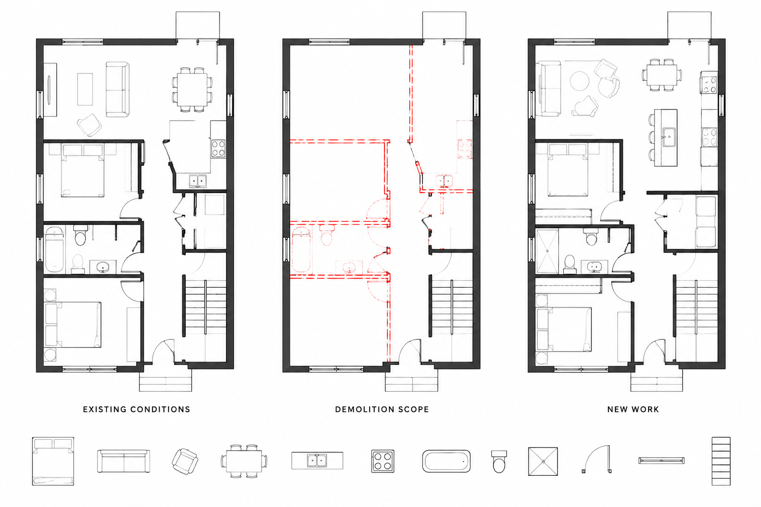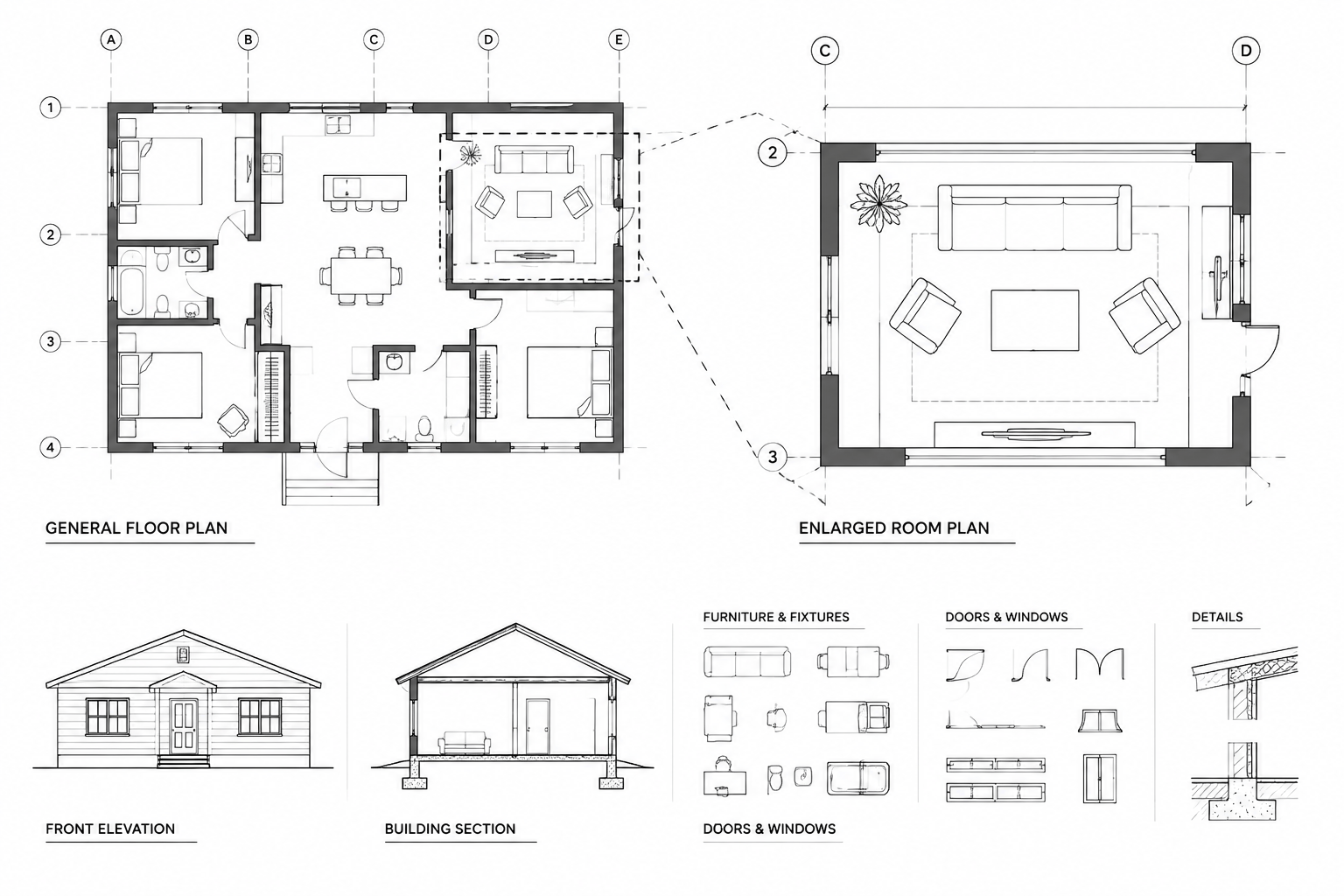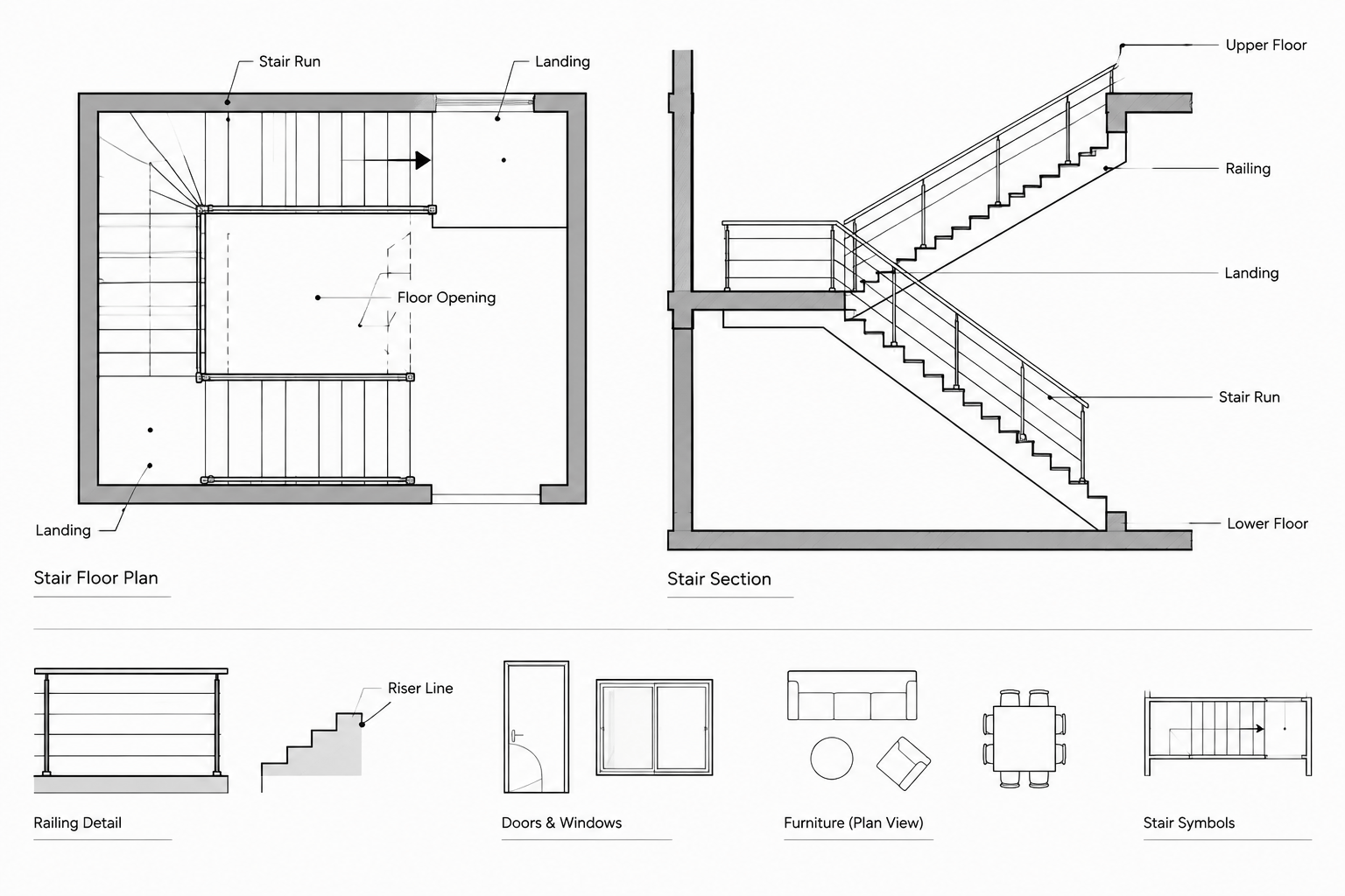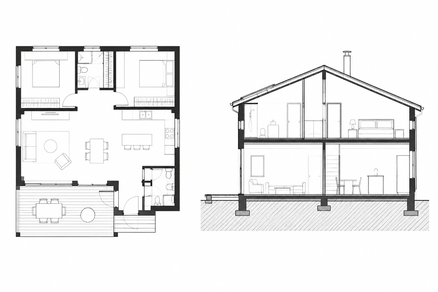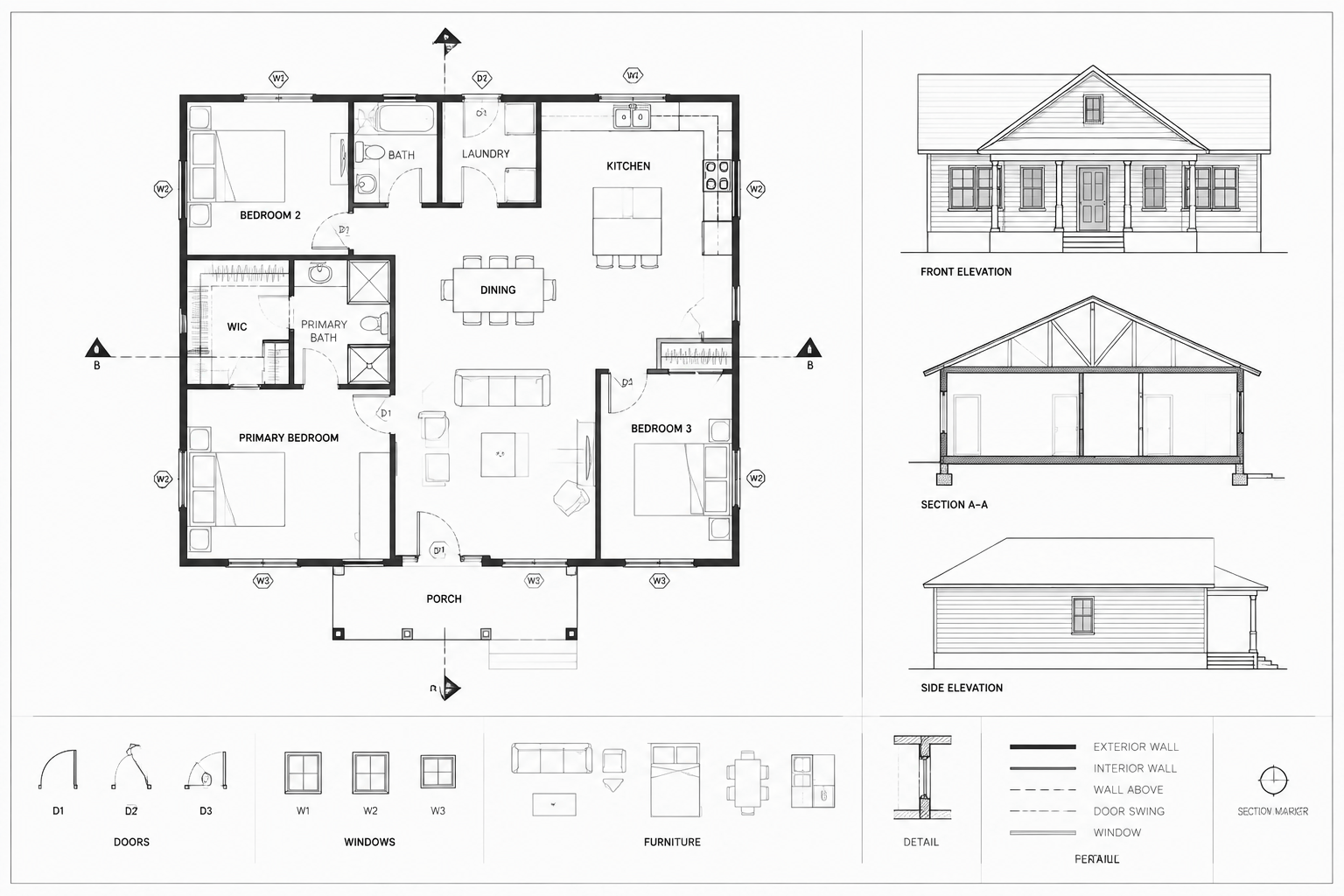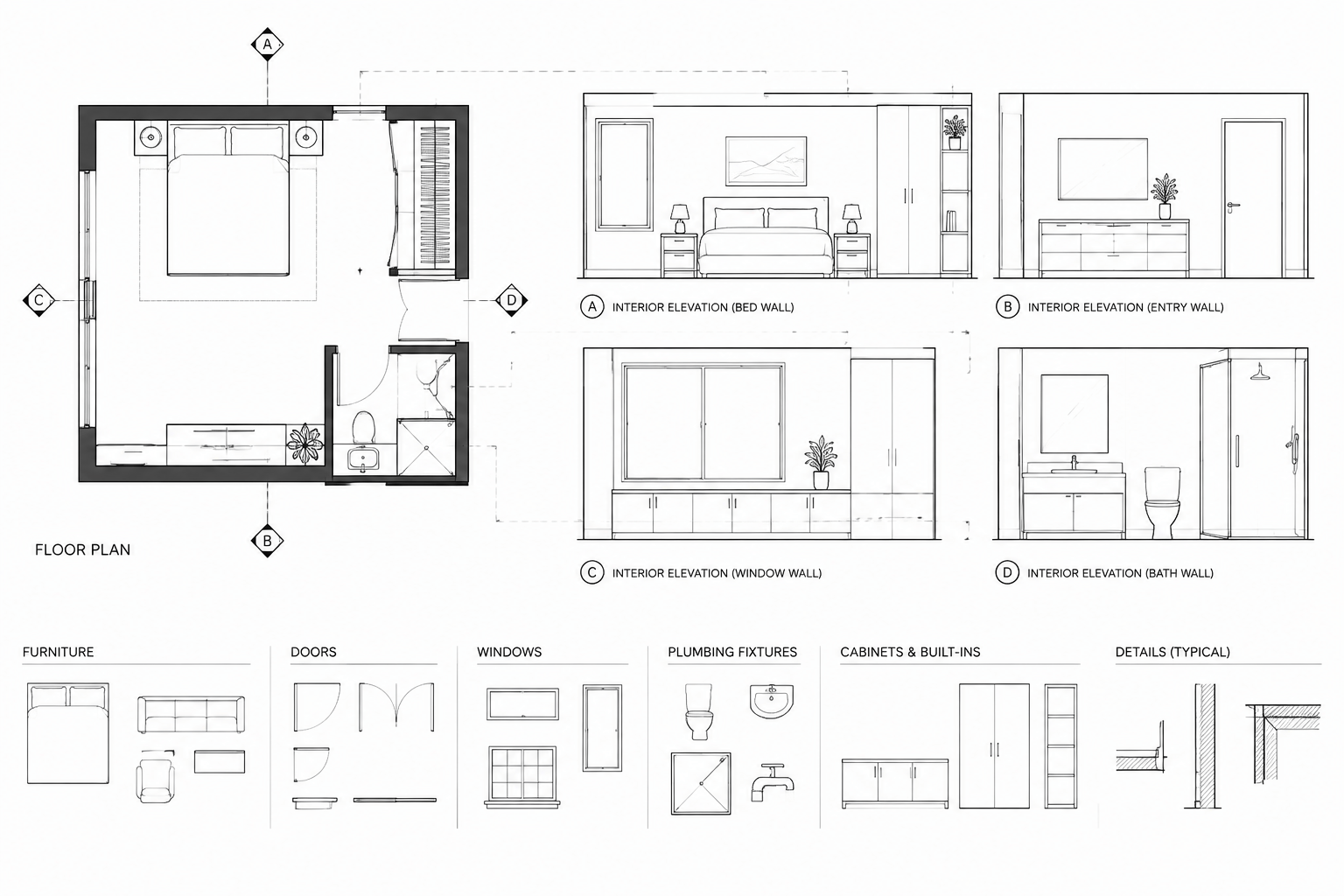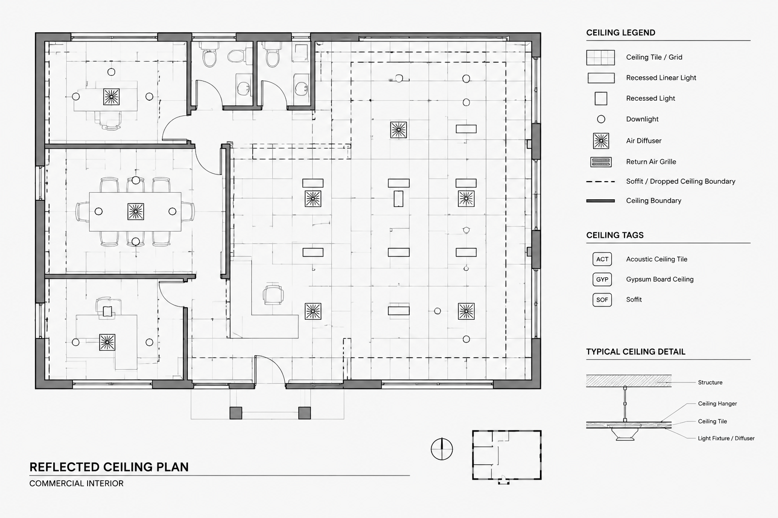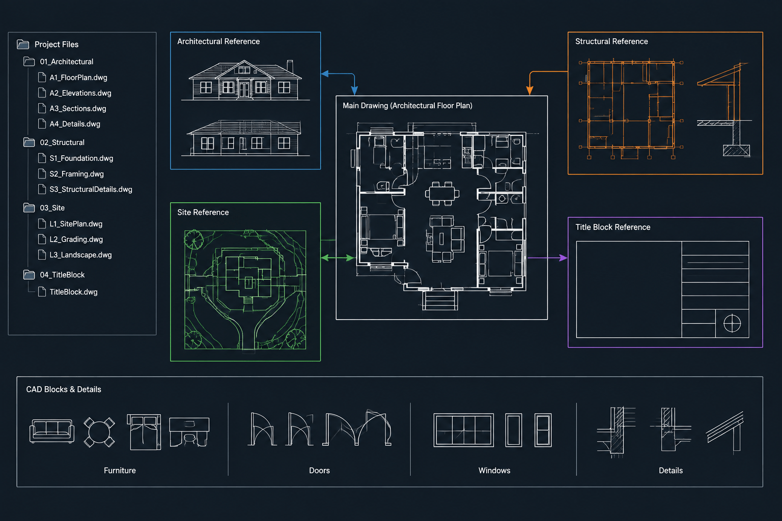
External references, commonly called xrefs, allow an architectural CAD team to divide a project into manageable drawing files while viewing them together as a coordinated model. A floor plan can reference a structural background, reflected ceiling plan, furniture layout, consultant drawing, or site base without permanently copying that geometry into the host DWG.
This approach can reduce duplicated work and make updates easier, but only when the reference structure is planned. Unclear file names, broken paths, uncontrolled nested references, and edits made in the wrong file can quickly undermine the benefits. The following workflow explains how to use architectural CAD external references as part of a reliable drawing organization system.
What an external reference does
An xref displays the contents of another drawing inside the current drawing. The referenced geometry remains stored in its source file. When that source changes, the host drawing can reload it and display the updated information.
This differs from inserting an ordinary block. A block definition becomes part of the receiving drawing, while an xref maintains a connection to an external file. That connection makes xrefs useful for backgrounds and project information that may continue to change.
A typical architectural sheet might contain:
- A referenced architectural floor-plan model.
- A title block or sheet border managed as a separate file.
- Consultant backgrounds used for coordination.
- A survey, civil base, or site drawing.
- Referenced plans used to align enlarged rooms or partial plans.
An xref is not automatically accurate simply because it loads correctly. Units, insertion point, rotation, drawing origin, and source-file content still need to be checked.
Plan the file structure before attaching drawings
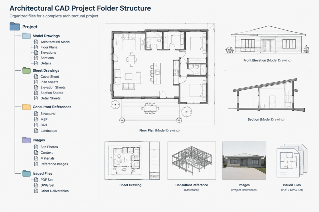
A predictable folder structure is one of the best defenses against missing references. Keep project drawings, references, issued files, and incoming consultant information separated according to a documented office convention. Avoid attaching live production files from temporary download folders, email attachment locations, personal desktops, or removable drives.
A practical project structure may distinguish among architectural model files, architectural sheets, consultant references, images, and published deliverables. The exact folder names are less important than consistency and team understanding.
Use descriptive drawing names
File names should indicate a drawing’s role without requiring users to open it. A consistent name can identify the discipline, area, level, content, or sheet function. Avoid vague names such as plan-new, latest, or final-final. Those labels do not explain whether a file is a model, a sheet, a consultant background, or an archived copy.
Revision status should be managed through the project’s agreed document-control process rather than through improvised file-name additions. Renaming a live reference can break its connection in every host file that depends on it.
Choose a suitable reference path
When a drawing is attached, CAD software stores information describing where the source file can be found. The available path options generally include relative, full, and no-path approaches. The best choice depends on how the project is stored and transferred.
| Path approach | Practical use | Coordination concern |
|---|---|---|
| Relative path | Useful when project folders maintain the same relationship to one another | The folder relationship must remain intact when the project is moved |
| Full path | Points to a specific storage location | Can fail when another user has a different drive or server mapping |
| No saved path | May work when files are kept together or found through configured search locations | Can become ambiguous when duplicate file names exist |
Relative paths are often practical for a self-contained project directory because the entire project can be moved while preserving the internal folder relationships. Before adopting any method, confirm that it fits the team’s network, cloud, or document-management environment.
Understand attachment and overlay behavior
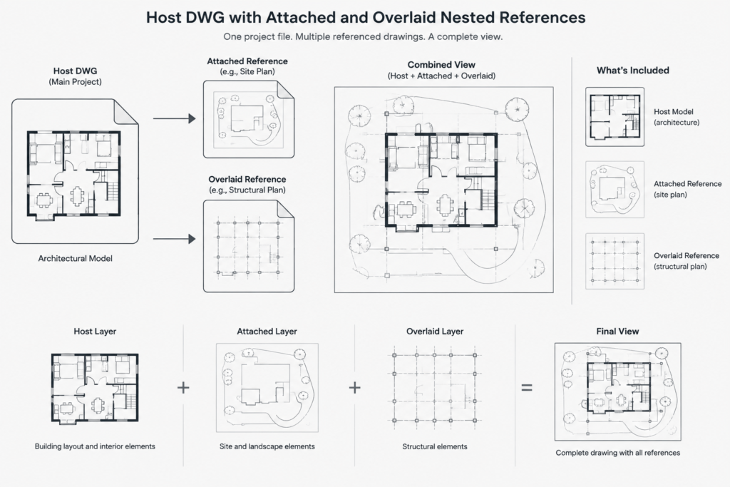
A DWG reference can generally be assigned as an attachment or an overlay. The difference matters when referenced files contain references of their own.
An attached xref can carry its nested references into another host drawing. An overlaid xref is visible in its immediate host but does not continue through additional levels of referencing. Overlay behavior is often useful for discipline backgrounds because it helps prevent the same file from appearing repeatedly through several reference chains.
Attachment behavior may be appropriate when a complete referenced assembly is intentionally expected to travel together. Do not select a type only because it makes the current view look correct. Consider how the file will behave when it is referenced into plans, elevations, sections, enlarged views, and sheets.
Establish a stable coordinate strategy
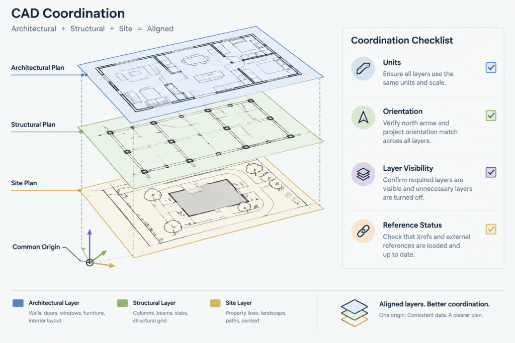
Referenced drawings coordinate most reliably when their teams agree on a common origin, orientation, and unit system. Repeatedly moving or rotating an xref by eye may solve an immediate visual problem while creating uncertainty elsewhere.
Before attaching a background, verify:
- The source drawing uses the intended drawing units.
- The architectural and consultant files share an agreed reference point.
- Project north, true north, and view rotation are clearly distinguished where relevant.
- The reference is not unintentionally scaled during insertion.
- Geometry is located within the expected project area rather than at an unexplained remote location.
If a received file does not align, investigate its coordinate basis before modifying it. Record any approved transformation so other team members can reproduce the setup. Moving consultant geometry inside the consultant’s file can make later replacements difficult unless that modification is part of an agreed workflow.
Separate model files from sheet files
A useful architectural CAD structure distinguishes drawing content from sheet presentation. Model files contain coordinated building geometry, while sheet files assemble views, annotations, title information, and plotted output.
For example, a floor-plan model can be referenced into several sheet files. Each sheet can show the appropriate area and scale through paper-space viewports while relying on the same underlying plan. This reduces the temptation to maintain separate copied plans for different sheets.
Not every office divides files in the same way. Some teams keep plan annotations with the model; others place sheet-specific notes and dimensions in sheet files. Either method can work if responsibilities are clear and the same information is not maintained in competing locations.
Control xref layers without editing the source
Referenced layers normally appear with a prefix that identifies the source drawing. This helps users distinguish host layers from xref layers. Visibility, color, linetype, and plotting behavior may be overridden in the host drawing when a particular sheet needs a different presentation.
Use overrides deliberately. A sheet may need a consultant background screened back or selected layers hidden, but extensive local overrides can conceal problems and make sheets difficult to troubleshoot. If a layer is wrong across many drawings, correcting the source file or shared layer standard may be more efficient than applying repeated host-file fixes.
Before plotting, check that:
- Required xref layers are visible in the relevant viewport.
- Temporary coordination layers are not being published.
- Layer overrides support a clear graphic hierarchy.
- Reference geometry does not mask architectural linework or annotation.
- Unexpected layers have not appeared after a source-file update.
Manage updates during coordination
When a referenced file changes outside the host drawing, the displayed version may need to be reloaded. Reloading should be followed by an actual review rather than treated as a clerical step. A consultant update can move openings, alter grids, change room boundaries, or add information that conflicts with architectural work.
Use a repeatable update process:
- Receive and identify the incoming file according to project document controls.
- Confirm its units, origin, orientation, and basic drawing condition.
- Replace or repath the approved project reference without changing the established relationship unnecessarily.
- Reload the reference in affected host drawings.
- Review coordination-sensitive areas and sheet graphics.
- Record significant issues through the team’s coordination process.
Do not assume that matching file names mean matching content. Similarly, avoid overwriting a current reference until the incoming file has been checked and the previous issue can be recovered if necessary.
Avoid circular and excessive reference chains
A circular reference occurs when drawings ultimately refer back to one another. Even when the software warns about or limits the loop, the file structure becomes harder to understand. Establish a clear direction of dependency: background models feed coordination or sheet files, rather than every file referencing every other file.
Deeply nested chains also make troubleshooting difficult. A layer visible on a sheet may originate several drawings away from the current host. Keep reference relationships as direct as practical, and document any intentional nesting.
Prepare files for sharing and issue
Before transmitting a drawing set, verify that recipients will receive every required reference, font, plot resource, image, and underlay permitted by the project agreement. A host DWG without its dependent files may open with missing backgrounds and incomplete sheets.
Use the software’s file-packaging or dependency-reporting tools where appropriate, but inspect the resulting package rather than assuming it is complete. Remove unrelated temporary material and respect any restrictions on consultant or proprietary files.
Binding an xref converts referenced content into information stored within the host drawing. This can be useful for a controlled archive or a specific exchange requirement, but it breaks the live external relationship and can introduce many layers or block definitions. Keep an unbound working copy and bind only for a defined purpose.
Final xref review checklist
- All required references are found and loaded.
- File names and folder locations follow the project convention.
- Path types support the team’s storage and transfer method.
- Attachment and overlay settings match the intended reference hierarchy.
- Units, origin, scale, and orientation have been verified.
- No unexplained duplicate or nested references are visible.
- Xref layer overrides produce the intended plotted hierarchy.
- Recent updates have been reviewed for coordination changes.
- Sheet files contain the correct models and presentation information.
- The issue package includes the approved dependencies.
A well-planned xref system does more than keep DWG files smaller. It clarifies ownership, supports coordinated updates, and makes architectural sheets easier to maintain. The key is to treat references as a project-wide information structure rather than as a convenient way to place one drawing inside another.