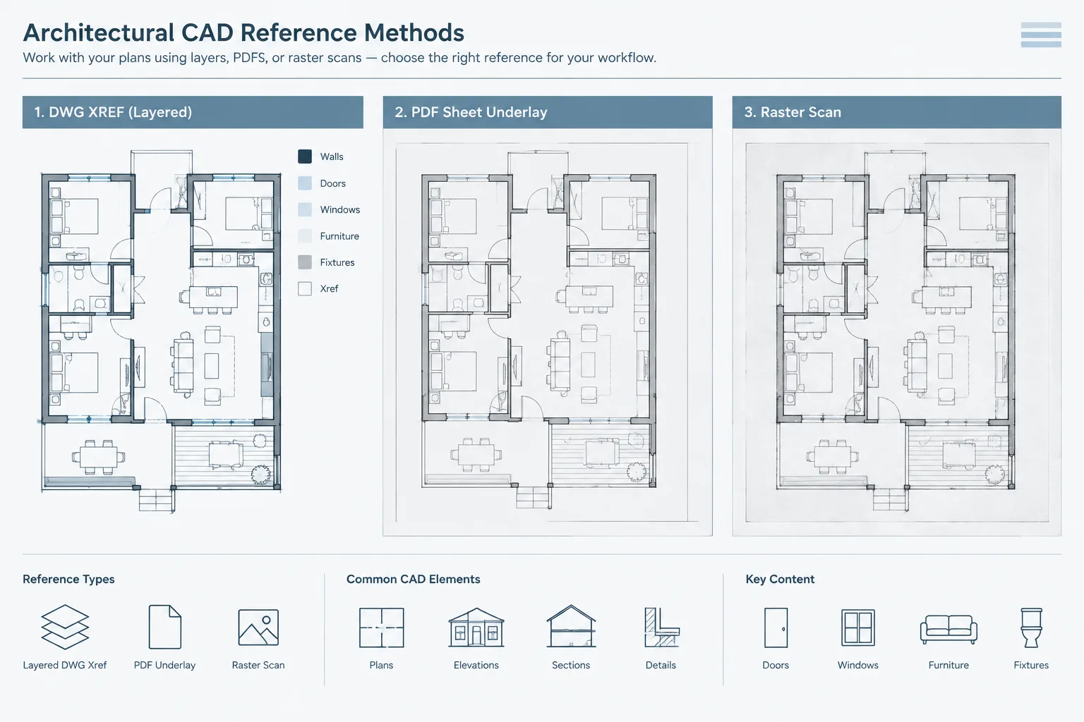
Choosing between an xref, PDF underlay, and raster image is not simply a file-format decision. It determines how confidently a CAD team can coordinate changes, verify scale, manage external dependencies, and distinguish source information from newly drafted work.
This guide compares the reference methods by purpose, reliability, update behavior, and drawing impact. Use it to select a workflow that preserves source context without allowing unverified information to become accidental project geometry.
Architectural CAD work often begins with information created somewhere else: a consultant drawing, survey, existing-condition sketch, scanned plan, product layout, or previously issued sheet. That reference information may arrive as a DWG file, a PDF, or an image. Although all three formats can appear behind CAD geometry, they do not provide the same accuracy, editability, coordination value, or file-management behavior.
Selecting the right reference method helps prevent scale errors, broken file paths, accidental tracing mistakes, and cluttered drawing files. The best choice depends on the source, how the information will be used, and whether the reference is expected to change.
What Is a Reference File in Architectural CAD?
A reference file supplies visual or geometric information without necessarily becoming permanent drawing geometry. It may support tracing, coordination, verification, or sheet composition. Common examples include structural backgrounds, civil base plans, consultant layouts, scanned field sketches, and record documents.
A reference should not automatically be treated as verified project information. Before relying on it, confirm its source, issue status, units, orientation, and relationship to the current design. A clear-looking attachment can still be outdated or incorrectly scaled.
DWG External References
A DWG external reference, commonly called an xref, is generally the strongest option when the source is a coordinated CAD drawing. The referenced file remains separate while its geometry is displayed in the host drawing.
When an xref is useful
- Coordinating architectural plans with structural, civil, mechanical, electrical, or plumbing backgrounds
- Separating floor plans, reflected ceiling plans, elevations, and other project files
- Maintaining repeated backgrounds used by multiple sheets or disciplines
- Receiving updates without manually copying replacement geometry into each host file
- Preserving the source file’s layers and object organization for visibility control
An xref supports an update-oriented workflow. When the referenced drawing is replaced or revised at the agreed location, host drawings can display the updated information. This makes it preferable to copying consultant geometry directly into an architectural file, where the copied objects may quickly become outdated.
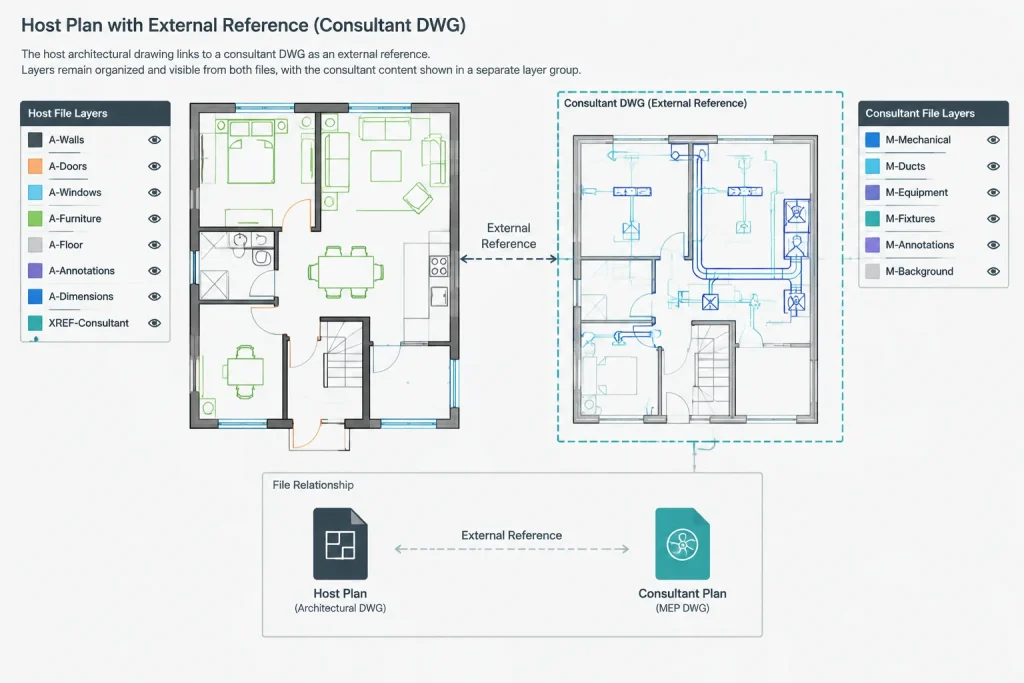
Potential xref problems
Xrefs require disciplined file management. Broken paths can cause references to disappear, while inconsistent units or insertion assumptions can produce incorrect size or location. Layer names from referenced drawings may also add complexity to layer lists.
Before using an xref, inspect the source file independently. Confirm that relevant geometry is near the expected project coordinates, unnecessary references are understood, and the drawing does not contain unexplained content far from the building. Coordinate any cleanup with the source owner rather than silently modifying consultant information.
PDF Underlays
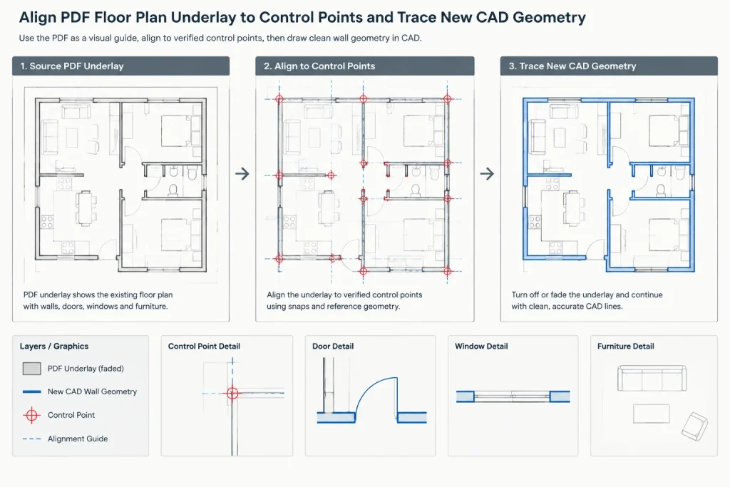
A PDF underlay is useful when a native CAD file is unavailable or when the goal is to compare against an issued document. PDFs may contain vector linework, raster content, or a mixture of both. Their apparent sharpness does not prove dimensional accuracy.
Appropriate PDF uses
- Reviewing an issued consultant sheet when no DWG background is available
- Tracing limited existing-condition information after scale verification
- Comparing a current drawing with a previously published sheet
- Displaying diagrams, sketches, or reference sheets during internal coordination
- Using recognizable control points to align supporting information
A PDF should be scaled from dependable known information, not from paper size alone. Sheet margins, printer settings, cropping, and earlier export processes can alter the relationship between the page and the original model. Verify more than one known distance in different directions where possible. If one area aligns while another does not, the source may be distorted or may not have been generated from accurate geometry.
Vector PDFs can be visually crisp and may provide more usable line information than scanned pages. However, text, hatches, line joins, and clipped graphics can still behave differently from native CAD objects. Treat the PDF as a reference unless there is a deliberate and checked reason to create CAD geometry from it.
Raster Images
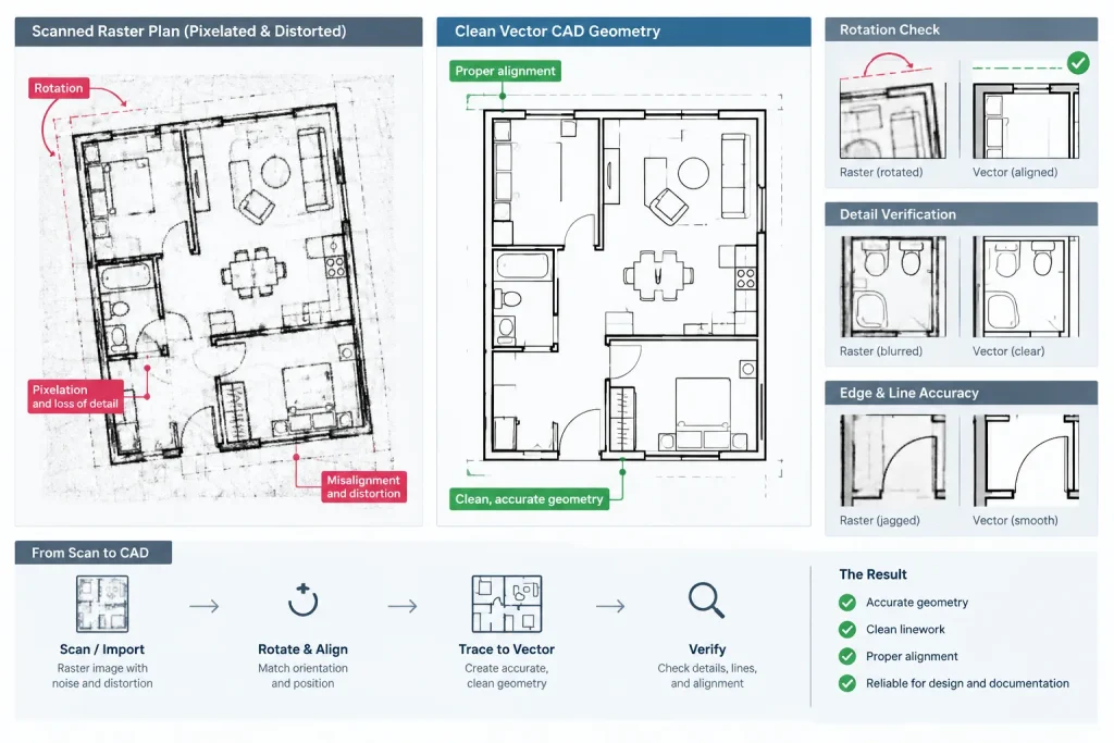
Raster references include scanned drawings, photographs, screenshots, and exported image files. They are composed of pixels rather than CAD vectors, so clarity depends on image resolution and the scale at which the image is viewed or plotted.
When raster images make sense
- Attaching a scan of a hand sketch or archival plan
- Using an aerial image as visual context rather than survey geometry
- Referencing field photographs or marked-up sketches
- Tracing a source that exists only as a scanned document
- Placing presentation graphics that are not intended to become CAD linework
Scans can contain rotation, stretching, page curl, lens distortion, and uneven scaling. Aligning one known length does not guarantee that the rest of the image is accurate. For that reason, raster tracing should be checked against multiple field measurements, survey points, or other reliable controls.
Large image files can also affect drawing performance and plotting. Crop the displayed area when appropriate, retain a practical source resolution, and avoid attaching unrelated images merely because they may be useful later.
DWG, PDF, and Raster Comparison
| Reference type | Primary strength | Main limitation | Typical architectural use |
|---|---|---|---|
| DWG xref | Coordinated CAD geometry with layer organization | Depends on units, coordinates, paths, and source-file discipline | Live backgrounds and multidisciplinary coordination |
| PDF underlay | Represents a published or exchanged document | May have uncertain scale or mixed vector and raster content | Issued-sheet review, comparison, and controlled tracing |
| Raster image | Accepts scans, photographs, and informal source material | Pixel-based and potentially distorted | Archival plans, sketches, photos, and visual context |
A Practical Selection Workflow
1. Identify the purpose
Decide whether the file is needed for live coordination, temporary comparison, measured tracing, or visual context. A changing consultant background usually favors an xref. An issued sheet may be better retained as a PDF underlay. A field sketch or scan generally requires a raster attachment.
2. Confirm source authority
Record who supplied the file, what it represents, and whether it is current. File format does not establish reliability. A native DWG may be obsolete, while a PDF may be the official issued record.
3. Check units, scale, and orientation
Verify the source against known project information before drafting from it. Check several control points, including points that are separated across the reference. Confirm rotation and project alignment rather than forcing the source to fit by eye.
4. Attach instead of embedding unnecessary content
Keeping source material external usually makes updates and responsibility clearer. Avoid copying an entire background into the working file unless there is a documented need and an appropriate cleanup process.
5. Control display separately
Make references visually subordinate to active architectural work. Use suitable layer visibility, fading, contrast, clipping, or plotting controls according to office workflow. The background should remain readable without competing with new geometry and annotation.
6. Test the plotted result
Review a PDF output rather than relying only on the model-space display. Check whether thin reference lines disappear, dense content becomes muddy, images print too dark, or clipped boundaries expose unwanted information.
7. Package external dependencies
When issuing or archiving drawings, include required reference files and preserve a usable folder relationship. A host DWG alone may not contain the xrefs, PDFs, images, fonts, or other dependencies needed to reproduce the drawing correctly.
Do Not Trace More Than the Project Needs
Tracing every line from a PDF or scan can create false precision and unnecessary maintenance. First determine which elements affect the architectural decision. A simplified outline may be sufficient for adjacent context, while verified walls, openings, columns, or site controls may require more careful reconstruction.
Separate traced geometry from the source reference so reviewers can distinguish interpreted CAD work from original information. Add notes or internal records describing assumptions that require field confirmation or consultant verification.
Final Recommendation
Use a DWG xref when coordinated, updateable CAD geometry is available. Use a PDF underlay when the published document itself is the important reference or when native geometry is unavailable. Use a raster image for scans, photographs, sketches, and other pixel-based sources.
Whichever format is selected, verify the source before relying on it, keep external files organized, and check the final plotted output. Reference files should support architectural decisions without disguising uncertainty or becoming accidental project geometry.
Build a Clear Information Hierarchy
A well-managed CAD file should make the status of each reference understandable. Active architectural geometry, consultant backgrounds, issued documents, archival records, and informal sketches should not appear equally authoritative. Their visual treatment and file organization should reflect how much confidence the project team places in them.
Consider recording the reference source, received status, intended use, and verification state in the project documentation. This creates an audit trail when a background is replaced, a published sheet conflicts with a native drawing, or traced information requires later confirmation.
Separate Alignment from Verification
A reference can be aligned correctly and still contain inaccurate information. Moving, rotating, or scaling a file only establishes its relationship to the host drawing; it does not confirm that the source geometry represents actual conditions.
Verification should therefore address both placement and content. Compare recognizable control information across the reference, investigate inconsistent results, and avoid adjusting separate areas merely to make them appear compatible. Local mismatches may indicate distortion, outdated information, or differences between surveyed, designed, and constructed conditions.
Plan for Replacement and Archiving
Reference management should anticipate future updates. Consistent file naming, controlled storage, and documented replacement procedures reduce the chance that a revised background will be attached beside an obsolete copy. Team members should be able to identify which source is current without relying on memory.
Before an issue or archive, review every external dependency from the recipient’s perspective. Confirm that required files are present, paths remain usable within the delivered folder structure, and plotted sheets reproduce the intended hierarchy. Also check whether a reference depends on additional external material that has not been included.
Use Traced Geometry as an Interpretation
Geometry traced from a PDF or image is a CAD interpretation of the source, not a conversion of uncertain information into verified fact. Keep that geometry identifiable through drawing organization and document assumptions that may affect design decisions.
Where source quality varies, prioritize the elements that matter to the current task. Selective, checked reconstruction is generally easier to review and maintain than a dense tracing that reproduces every visible mark without establishing what those marks mean.
Frequently Asked Questions
Is a DWG xref always more reliable than a PDF?
No. A DWG offers organized CAD geometry and update potential, but reliability depends on its source, issue status, units, coordinates, and content. An officially issued PDF may be the governing record even when an older DWG is available.
Can a PDF underlay be treated as dimensionally accurate?
Only after it has been checked against dependable project information. Export settings, cropping, page handling, and mixed vector or raster content can affect the result. Visual sharpness alone does not establish accuracy.
Why can a scanned plan align in one area but not another?
The scan may contain stretching, rotation, page deformation, photographic distortion, or inaccuracies in the original drawing. A single aligned distance cannot confirm the condition of the entire image.
Should reference geometry be copied into the host drawing?
Copying may be justified for a defined drafting task, but it removes the automatic relationship to the external source and can obscure responsibility for updates. Keep imported or traced work separate and document why it was created.
How should references appear in plotted drawings?
They should remain legible while staying visually subordinate to active geometry and annotation. Review the plotted output for excessive darkness, disappearing lines, clutter, exposed clipping edges, and image-quality problems.
What should be checked before sharing a referenced CAD file?
Review the host drawing together with its required xrefs, PDFs, raster images, fonts, and other dependencies. Confirm that the folder structure is usable and that the recipient can reproduce the intended drawing without access to undocumented local files.