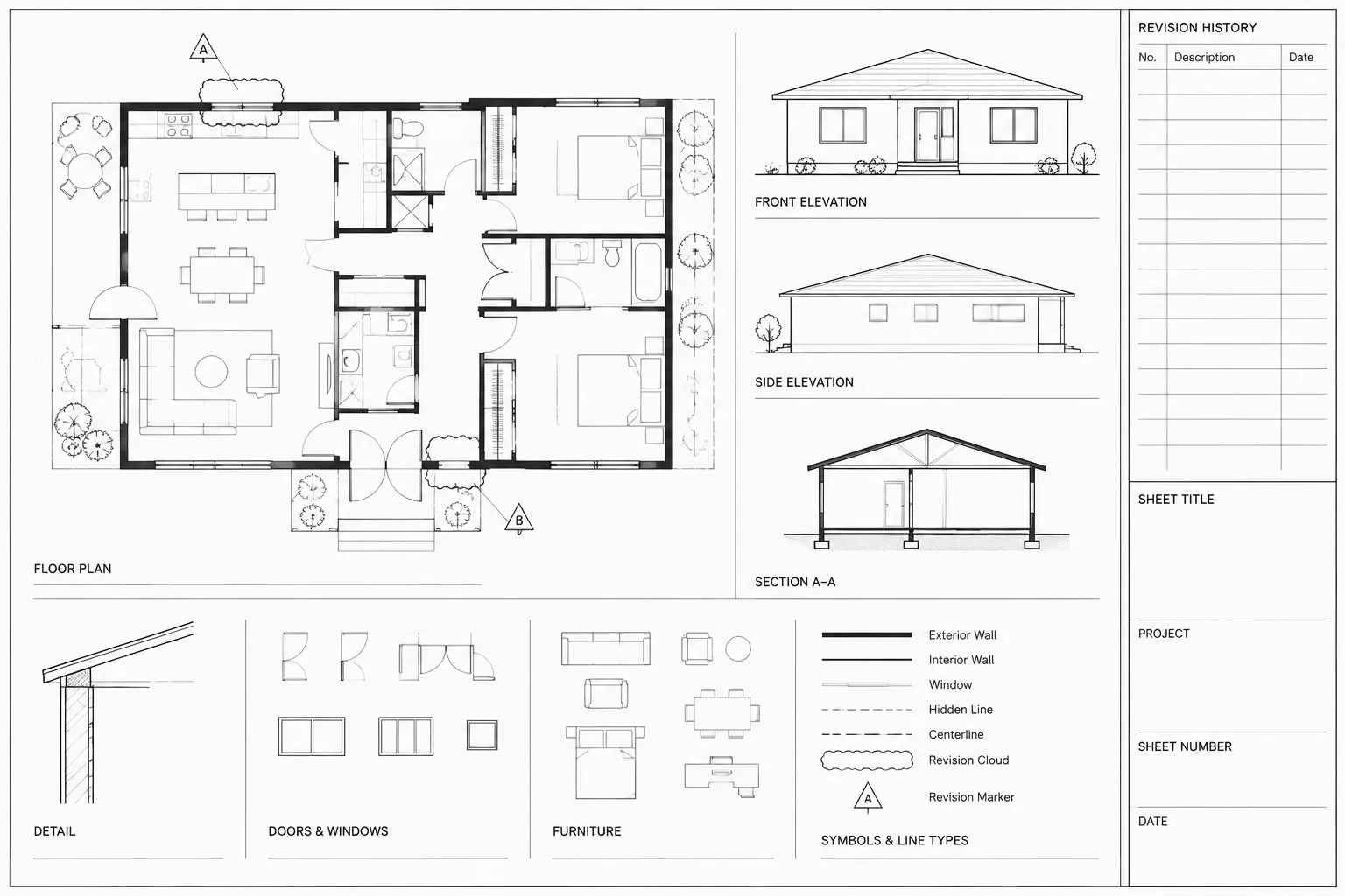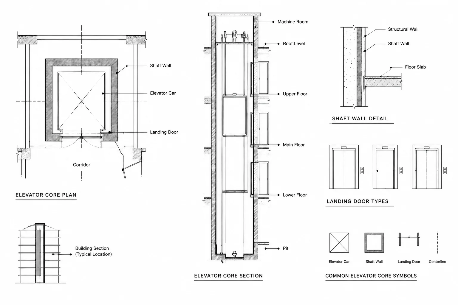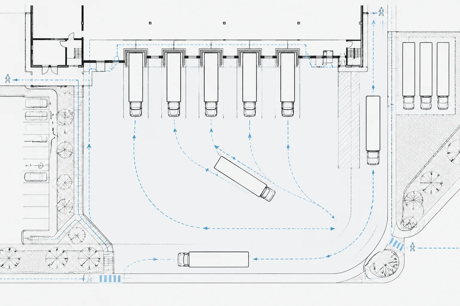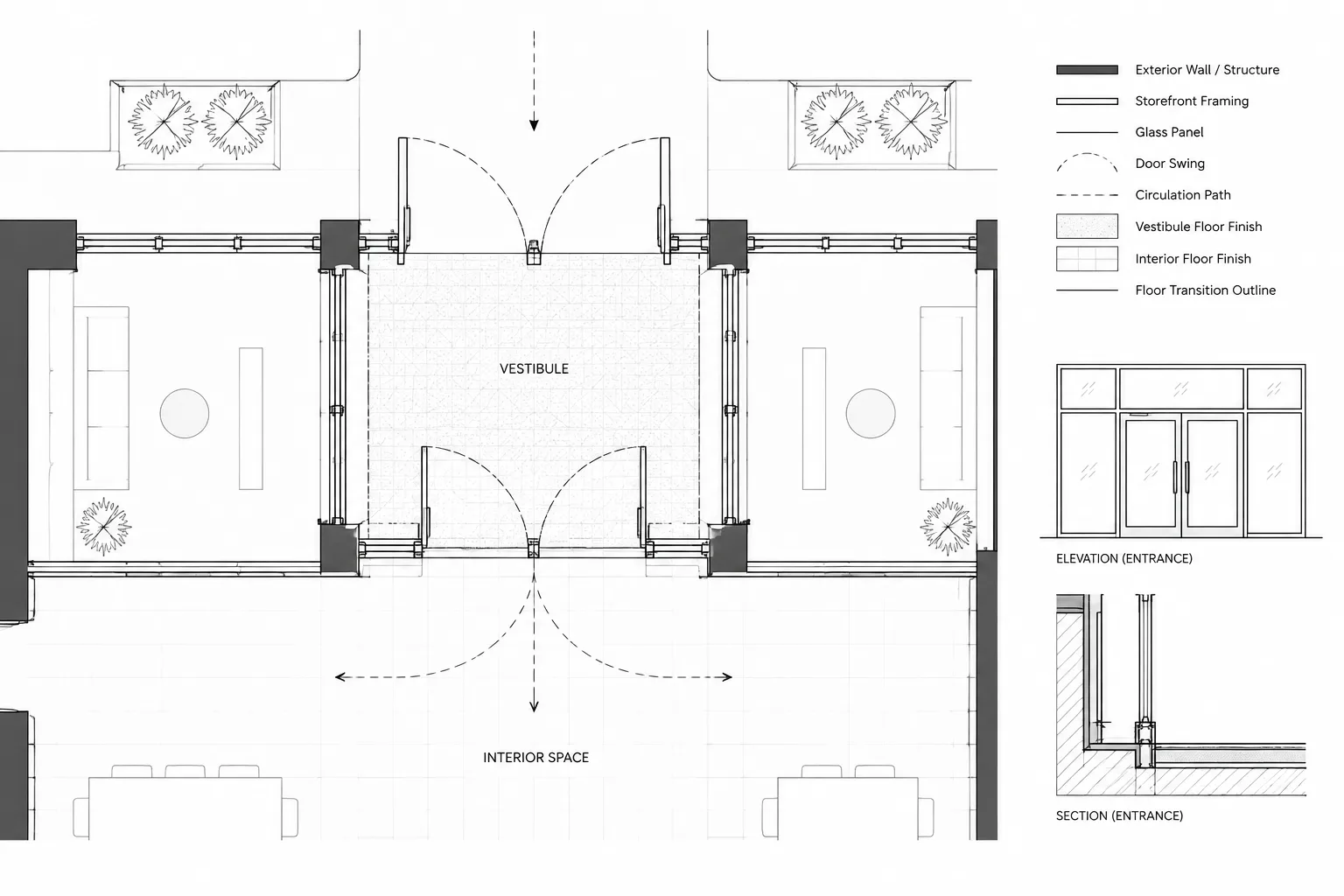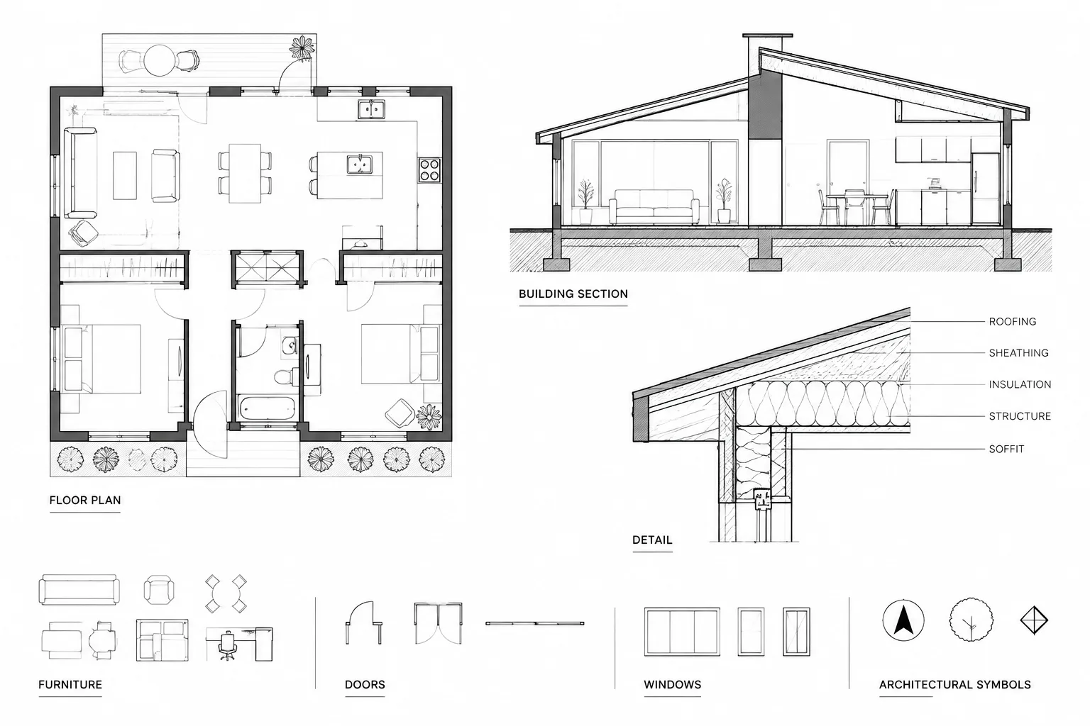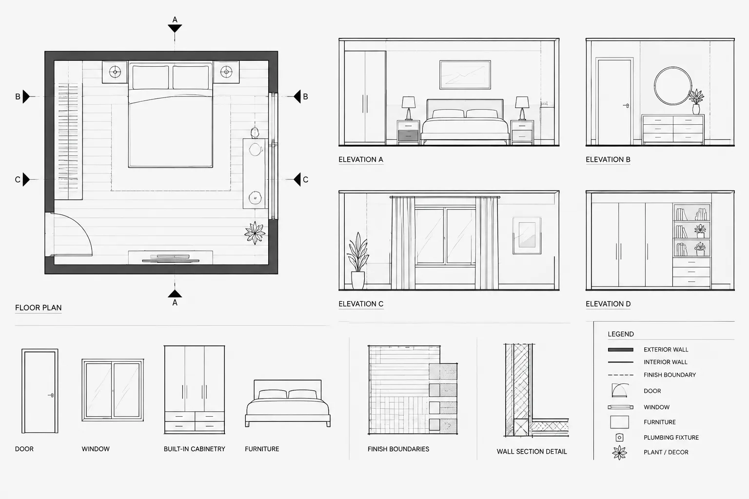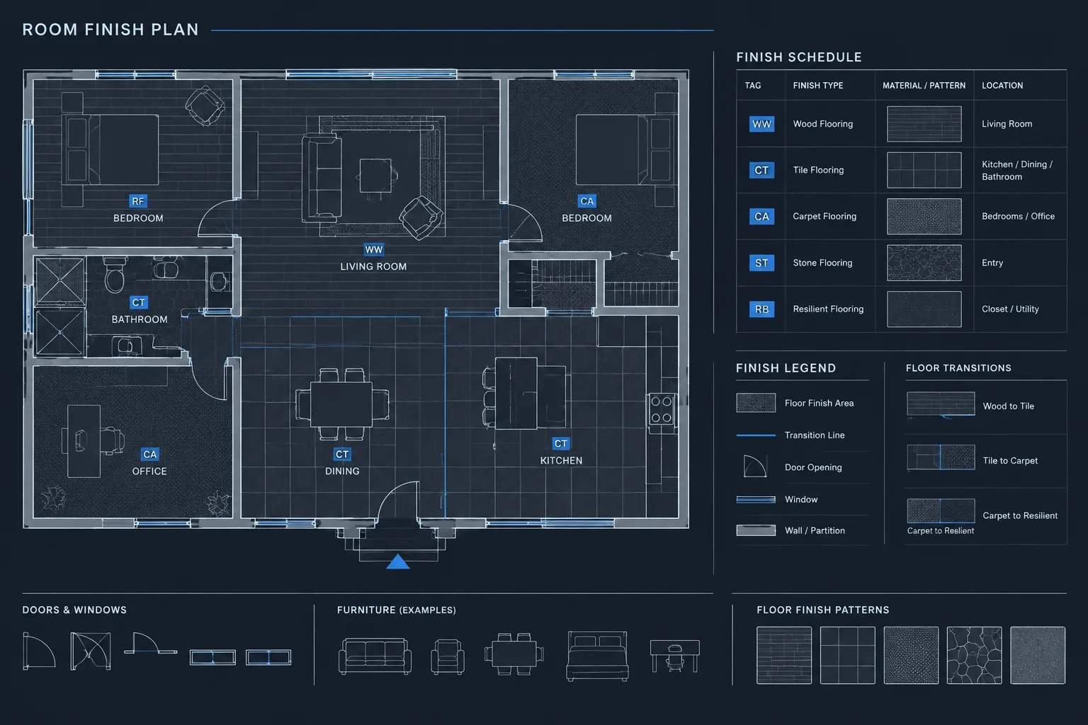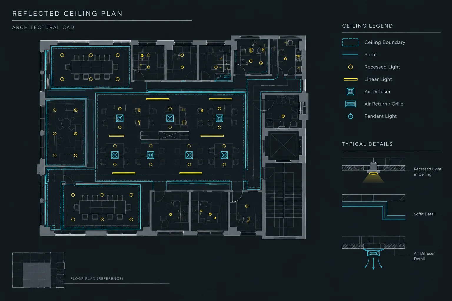
Paper space viewports in AutoCAD are central to producing coordinated architectural sheets from reusable model-space geometry. Their reliability depends on more than selecting a scale: viewport boundaries, displayed extents, layer visibility, annotation, and sheet titles must remain aligned throughout revisions.
The guidance below presents a practical control process for composing views, preventing accidental changes, and checking the plotted sheet. Use it alongside the project template and office drafting standards rather than treating viewport setup as an isolated plotting task.
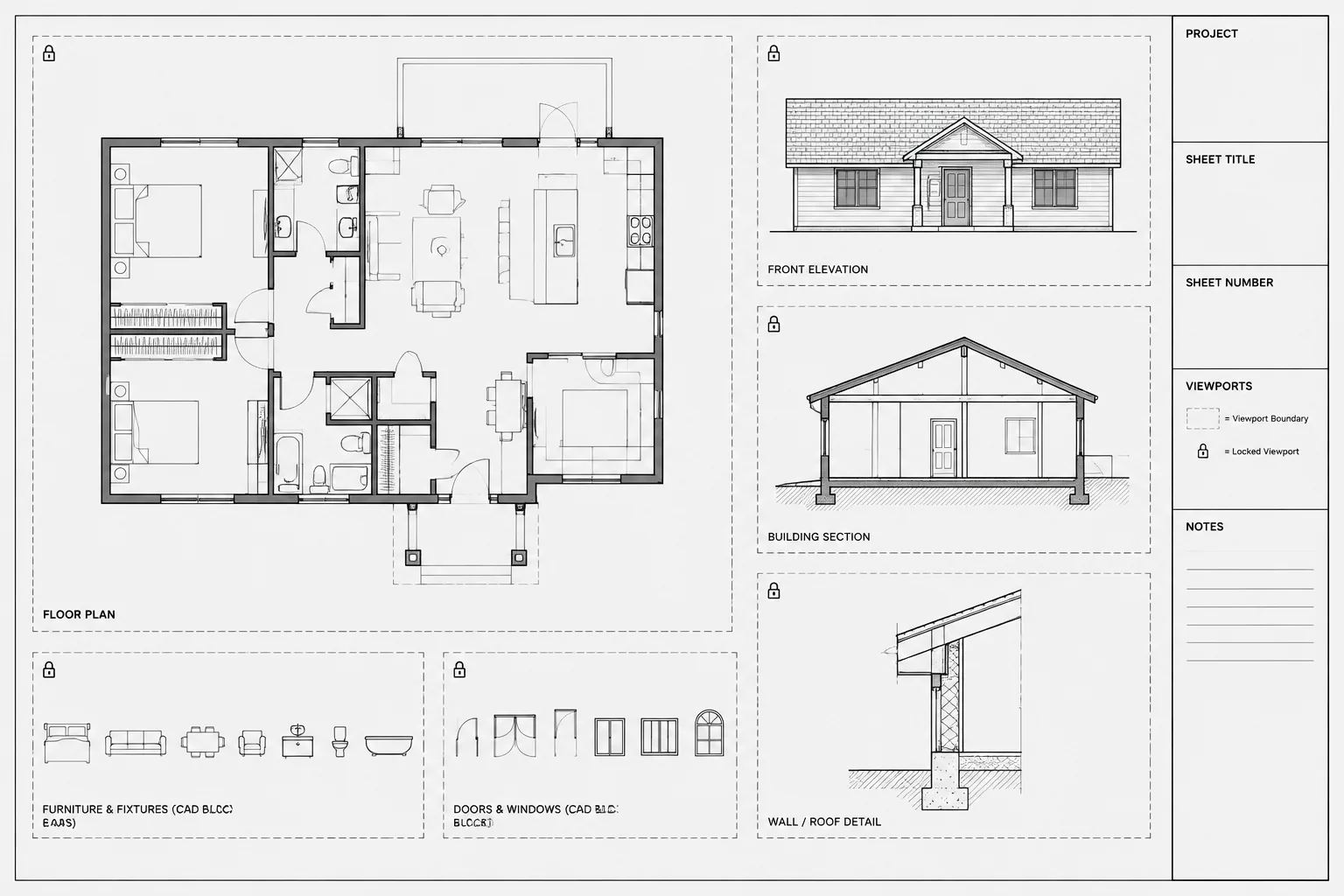
Paper space viewports connect full-size architectural geometry in model space to organized, printable views on a sheet. When they are managed carefully, one floor plan can support overall plans, enlarged areas, key plans, and coordination views without duplicating the building geometry. When they are managed poorly, a small accidental pan or scale change can disrupt dimensions, callouts, linework, and sheet composition.
This guide explains a practical workflow for setting up and controlling paper space viewports in AutoCAD. The emphasis is not merely on creating a viewport, but on keeping its scale, position, layer display, and relationship to the sheet dependable throughout design and documentation.
What a paper space viewport does
Model space is generally where architectural geometry is drawn at full size in the project’s established drawing units. Paper space represents a plotted sheet. A viewport is a paper space object that displays a selected portion of model space at a controlled scale.
This separation allows the same model-space geometry to appear on multiple sheets or multiple times on one sheet. Each viewport may show a different area, scale, orientation, or layer configuration while referring to the same underlying objects.
A viewport should therefore be treated as a coordinated drawing component rather than as a simple window. Its setup affects what the reader sees, how annotations relate to the view, and whether the sheet remains stable after revisions.
Establish the layout before creating viewports
Begin with a layout that already has the correct sheet framework. Confirm the title block, printable area, page setup, plot style, paper size, and output device or PDF configuration used by the project. Viewports arranged before the page setup is verified may need extensive repositioning later.
It is also helpful to identify the intended sheet content before drawing viewport boundaries. Consider:
- The primary view that should dominate the sheet.
- Supporting plans, enlarged views, diagrams, or key plans.
- Space required for titles, notes, legends, schedules, and revision information.
- Margins needed between view graphics and the title block.
- Whether adjacent sheets should use matching view extents or alignment.
A quick sheet-composition sketch can prevent repeated resizing and rearrangement. The goal is to make the viewport serve the drawing hierarchy rather than filling every available area.
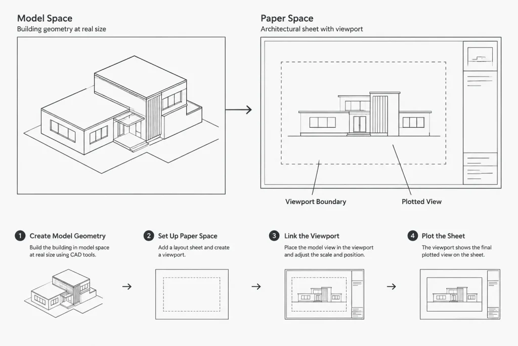
Create viewports on a dedicated layer
Place viewport boundaries on a dedicated paper space layer. This makes them easier to select, inspect, lock, and control during plotting. The viewport layer is commonly configured so its boundary does not print, but the exact layer name and plot behavior should follow the office template.
Do not place viewport frames on an unrelated annotation or title-block layer. A dedicated layer reduces the chance that viewport boundaries will plot unexpectedly or become difficult to find among other paper space objects.
Start with a simple rectangular viewport when possible. Irregular or clipped viewports can be useful for special sheet arrangements, but they introduce more complex edges and may make later adjustments less intuitive. Use them because the presentation requires them, not merely to fit geometry into leftover space.
Set the view and scale deliberately
After creating a viewport, activate its model-space view and navigate to the required area. Set the intended viewport scale using a controlled scale selection or the project’s established method. Avoid relying on visual approximation with the mouse wheel.
The viewport scale should reflect the amount of information and graphic detail shown. An overall plan usually needs a broader field of view than an enlarged room plan or detail. The selected scale must also agree with the view title and any scale notation elsewhere on the sheet.
A dependable sequence is:
- Create the viewport in paper space.
- Activate the view through the viewport.
- Select the required architectural area.
- Apply the intended scale precisely.
- Pan to compose the view without changing its scale.
- Return to paper space.
- Lock the viewport.
If the view no longer fits after the scale is applied, resize the paper space viewport boundary or reconsider the sheet composition. Do not choose an unsuitable scale simply to force the plan into an existing frame.
Lock viewports as soon as they are composed
Viewport locking is one of the simplest protections against sheet errors. An unlocked viewport can be zoomed accidentally while a user is trying to inspect or edit model-space content through the layout. The result may be a subtle scale change that is not noticed until plotting or review.
Lock each viewport after its scale and view position are established. If a revision requires recomposing the view, unlock it intentionally, make the change, verify the scale, and lock it again.
Locking does not prevent edits to model-space geometry. It protects the viewport’s displayed magnification and helps keep the sheet composition stable. Teams should include viewport lock status in routine drawing checks rather than treating it as an optional cleanup task.
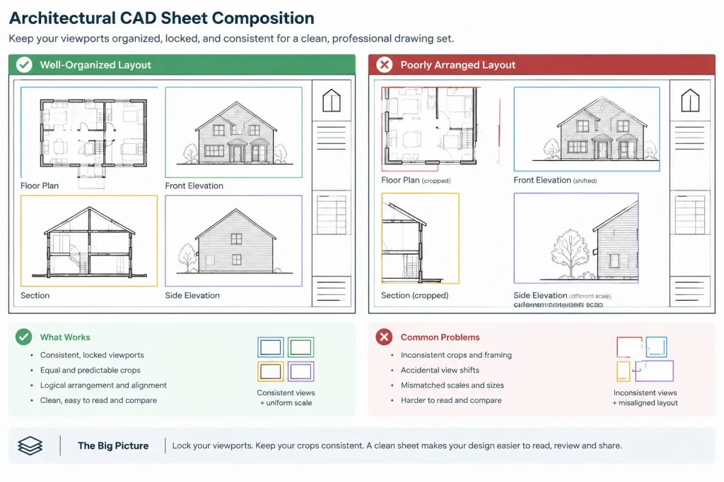
Pan without losing scale control
Once a precise scale has been assigned, use panning to center the required content. Avoid zooming as a positioning method because zooming can change the viewport scale when the viewport is unlocked.
When several related sheets show adjacent portions of a plan, establish recognizable alignment references in model space. Grid lines, major walls, or other stable project geometry can help coordinate the views. Match lines and reference callouts should then agree with the actual extents shown on each sheet.
For repeated layouts, named views may help users return to established model-space extents. However, restoring a view does not eliminate the need to verify the viewport scale, position, and lock status on the finished sheet.
Control viewport-specific layer visibility carefully
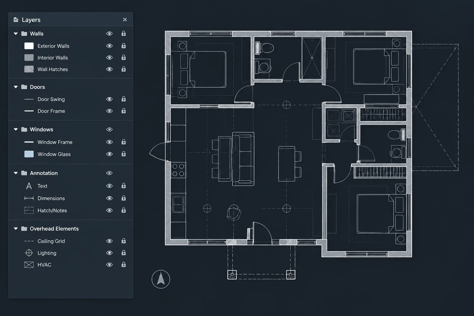
A paper space viewport can show a layer configuration that differs from other viewports. This is useful when the same base drawing supports several presentation purposes. For example, a coordination view may display reference information that is hidden from a clean architectural plan.
Viewport-specific controls should be used with discipline. A layer hidden only in one viewport can be overlooked during troubleshooting because it remains visible elsewhere. Before applying an override, ask whether the difference is truly view-specific or whether the object belongs on a more appropriate layer.
Maintain a clear distinction between:
- Global layer changes that affect the drawing generally.
- Viewport-specific visibility changes used for one presentation.
- Viewport graphic overrides used to adjust plotted appearance without changing the source objects.
When a line is missing from a sheet, check viewport-specific layer settings as well as global layer status, object properties, clipping, and draw order.
Coordinate annotation with viewport behavior
Annotations may be placed in model space, paper space, or through a controlled hybrid workflow. Whatever method the project uses, viewport scale must remain coordinated with text, dimensions, symbols, and callouts.
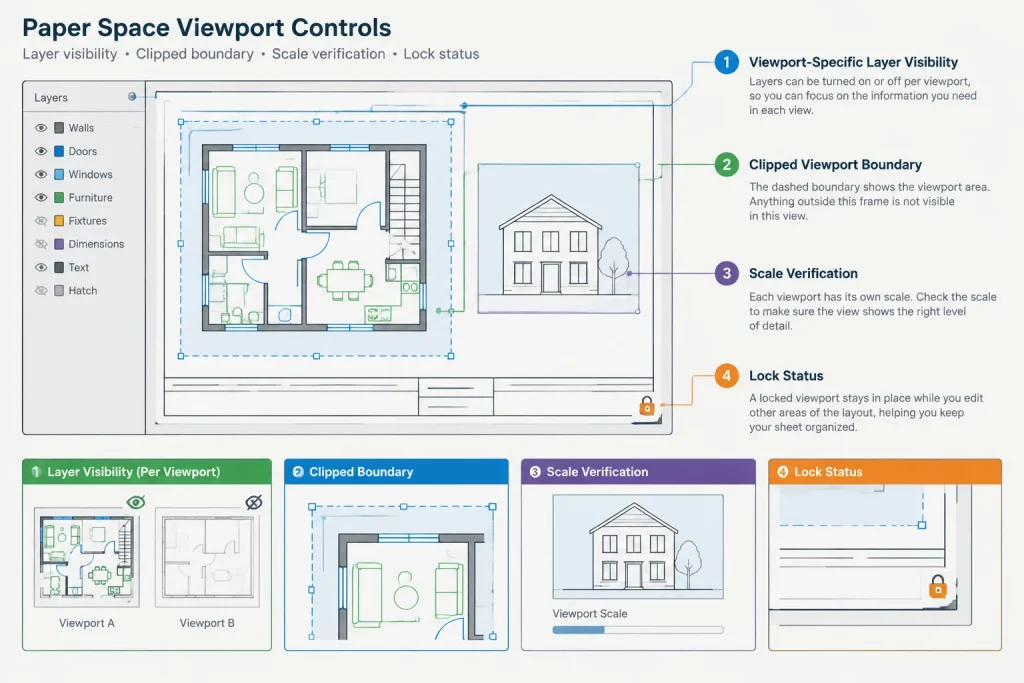
Paper space view titles should identify the displayed view and state its scale according to the office standard. A title that no longer matches the viewport is a documentation error even if the geometry itself is correct.
For model-space annotation intended to appear through multiple scaled viewports, confirm that the annotation setup supports the required display conditions. Do not assume text or dimensions will remain readable merely because the viewport scale is correct. Plot-based review is essential.
Use clipped and overlapping viewports cautiously
Clipped viewports can create useful nonrectangular presentation areas, but their boundaries should remain understandable and easy to edit. Complex clipping shapes may conceal geometry unexpectedly or make selection difficult.
Overlapping viewports deserve particular attention. One viewport may cover another with its background or display content in an unintended stacking order. Keep viewport arrangements simple where possible, inspect draw order, and review the resulting PDF rather than relying only on the layout display.
If a sheet requires many small, tightly cropped views, consider whether separate layouts or a more structured sheet arrangement would be easier to maintain.
Common viewport problems and likely causes
| Problem | Likely cause | Practical check |
|---|---|---|
| The plan appears at the wrong size | The viewport scale changed or was set approximately | Confirm the viewport’s scale property and compare it with the view title |
| The view shifted on the sheet | The viewport was unlocked and panned accidentally | Recompose the view, verify scale, and lock it |
| Objects appear in one viewport but not another | Viewport-specific layer visibility differs | Inspect the affected layers while the correct viewport is active |
| The viewport frame prints | The boundary is on a plotting layer | Move it to the designated nonplot viewport layer |
| Annotation is missing or unreadable | The annotation method does not match the viewport setup | Check annotation location, scale behavior, layers, and plotted size |
| A clipped view hides required geometry | The clipping boundary is too restrictive or outdated | Edit the boundary and compare it with the intended view extent |
Quality-control checklist before issue
Viewport review should be performed in the layout and in the plotted output. Before issuing a sheet, verify the following:
- Every viewport uses the intended scale.
- Each stated view scale agrees with the actual viewport.
- Viewports are locked after final composition.
- Viewport boundaries do not print unless intentionally shown.
- Plans are centered and cropped without omitting required information.
- Match lines, callouts, and adjacent sheet references agree with the displayed extents.
- Viewport-specific layer settings are intentional.
- Text, dimensions, symbols, hatches, and lineweights remain readable in the PDF.
- No overlapping viewport obscures another view.
- Revisions to model-space geometry remain visible in every relevant viewport.
A stable viewport workflow supports reliable sheets
Paper space viewports are most dependable when their setup follows a repeatable sequence: establish the sheet, create viewports on a controlled layer, assign exact scales, compose views by panning, apply necessary layer controls, and lock the results. The final PDF should then be reviewed as the actual communication product.
This approach keeps model geometry reusable while allowing each sheet to present a specific architectural view. More importantly, it reduces the risk that ordinary navigation or late revisions will quietly alter the scale and composition of a drawing set.
Managing viewport changes during revisions
Viewport coordination becomes especially important when a sheet has already been composed and the model continues to change. A revision to walls, grids, room boundaries, or referenced information may alter the visual balance of a view without changing its assigned scale. Review the displayed extents after significant model updates, but avoid recomposing a viewport unless the sheet actually requires it.
When adjustment is necessary, use a controlled sequence: confirm which viewport is active, unlock it intentionally, pan or revise its boundary, verify its scale and layer display, then lock it again. The related view title, callouts, match lines, and references should be checked at the same time.
Distinguish viewport geometry from displayed geometry
A viewport boundary is a paper space object, while the building information seen through it remains in model space. This distinction helps diagnose selection and editing problems. If the frame itself must move or change shape, work with the viewport in paper space. If the displayed building geometry must change, edit the appropriate model-space objects while protecting the viewport composition.
Before deleting or recreating a problematic viewport, inspect its lock status, scale, clipping boundary, layer overrides, and draw order. Rebuilding may remove useful view-specific settings and can create additional coordination work.
Coordinate viewports as part of the sheet set
A viewport should not be reviewed only as an individual frame. Compare it with adjacent plans, enlarged views, key plans, and referenced sheets. Shared alignment features should appear consistently, and the visible extents should support the references used to guide the reader through the drawing set.
For team handoff, make viewport intent easy to understand. Consistent layer use, clear view titles, locked compositions, and restrained use of clipping or overrides allow another drafter to revise the sheet without having to reconstruct how each view was assembled.
Review the communication result
The plotted output is the final test of viewport management. Layout display alone may not reveal every issue involving lineweights, hatches, annotation, clipping, or overlapping views. Review the output for both technical correctness and drawing hierarchy: the main view should remain clear, supporting views should be identifiable, and no viewport-specific setting should hide information needed to interpret the sheet.
Frequently asked questions
Why should a paper space viewport be locked?
Locking protects the established magnification and helps prevent accidental zooming or panning. It does not stop users from editing the model-space geometry displayed through the viewport.
Should viewport boundaries be placed on their own layer?
Yes. A dedicated paper space layer makes viewport frames easier to select, inspect, and control. Its plotting behavior should follow the project template so boundaries do not appear unintentionally in the issued output.
Can several viewports display the same model-space geometry?
Yes. Separate viewports can present different areas, scales, orientations, or layer configurations while referencing the same underlying geometry. This avoids duplicating the building model solely for sheet presentation.
Why is an object visible in one viewport but missing in another?
The affected viewport may have different layer visibility or graphic overrides. Also inspect global layer status, object properties, clipping, and draw order before changing the source geometry.
Should a viewport be zoomed to center a plan?
After assigning the intended scale, use panning to compose the view. Zooming an unlocked viewport can change its scale and create a mismatch with the view title.
What should be checked after changing a viewport?
Verify the displayed area, assigned scale, lock status, boundary, layer settings, annotation, view title, callouts, and related sheet references. Then inspect the plotted output.
When is a clipped viewport appropriate?
A clipped viewport can support a specialized sheet arrangement when a rectangular frame does not provide the required presentation. Keep the clipping boundary understandable and confirm that it does not conceal necessary geometry.