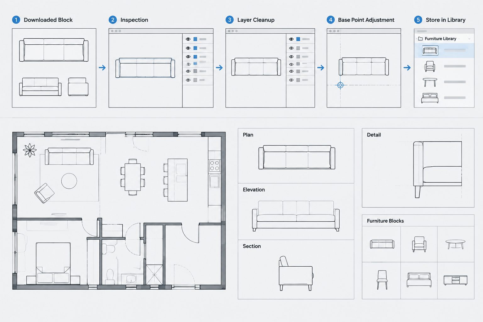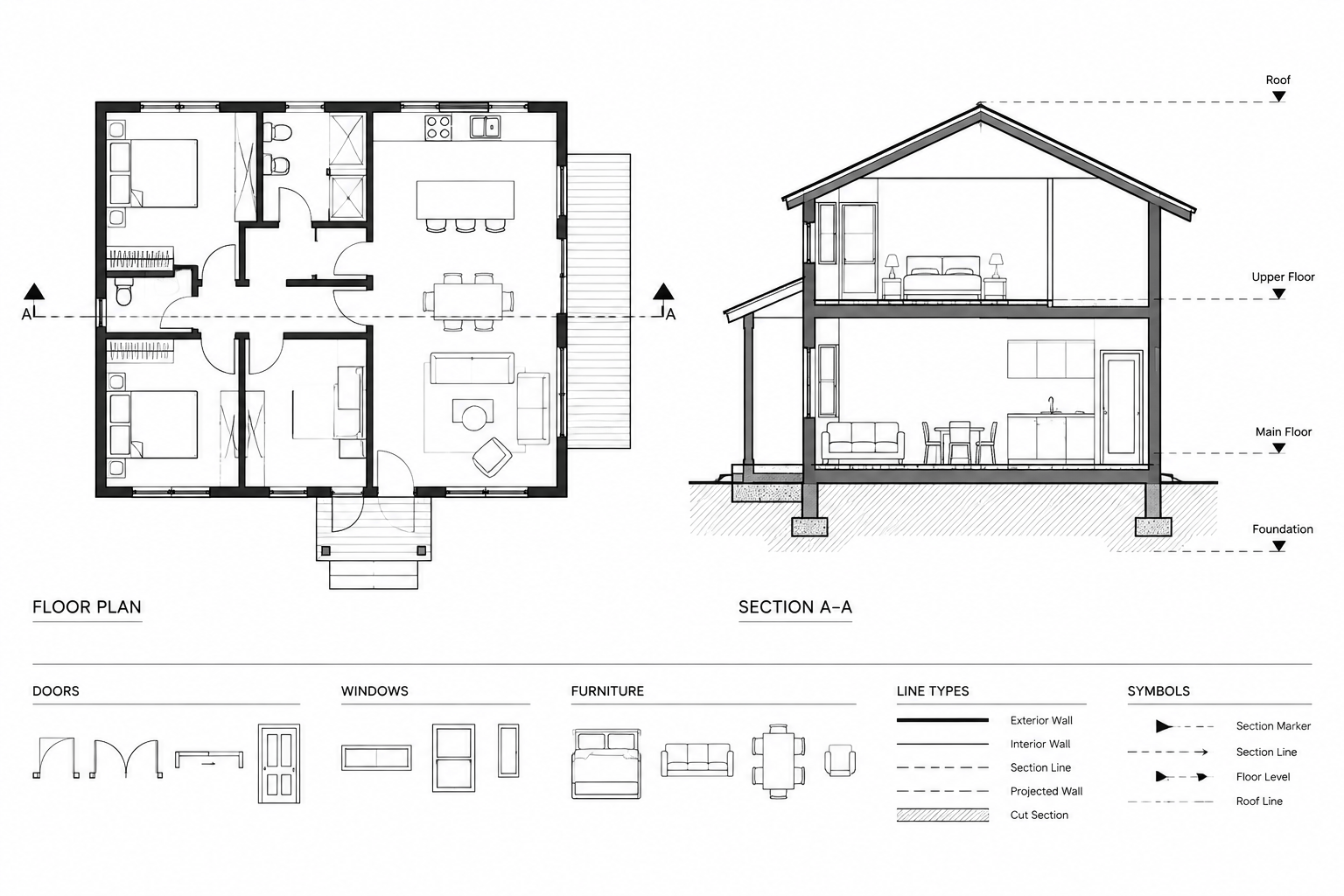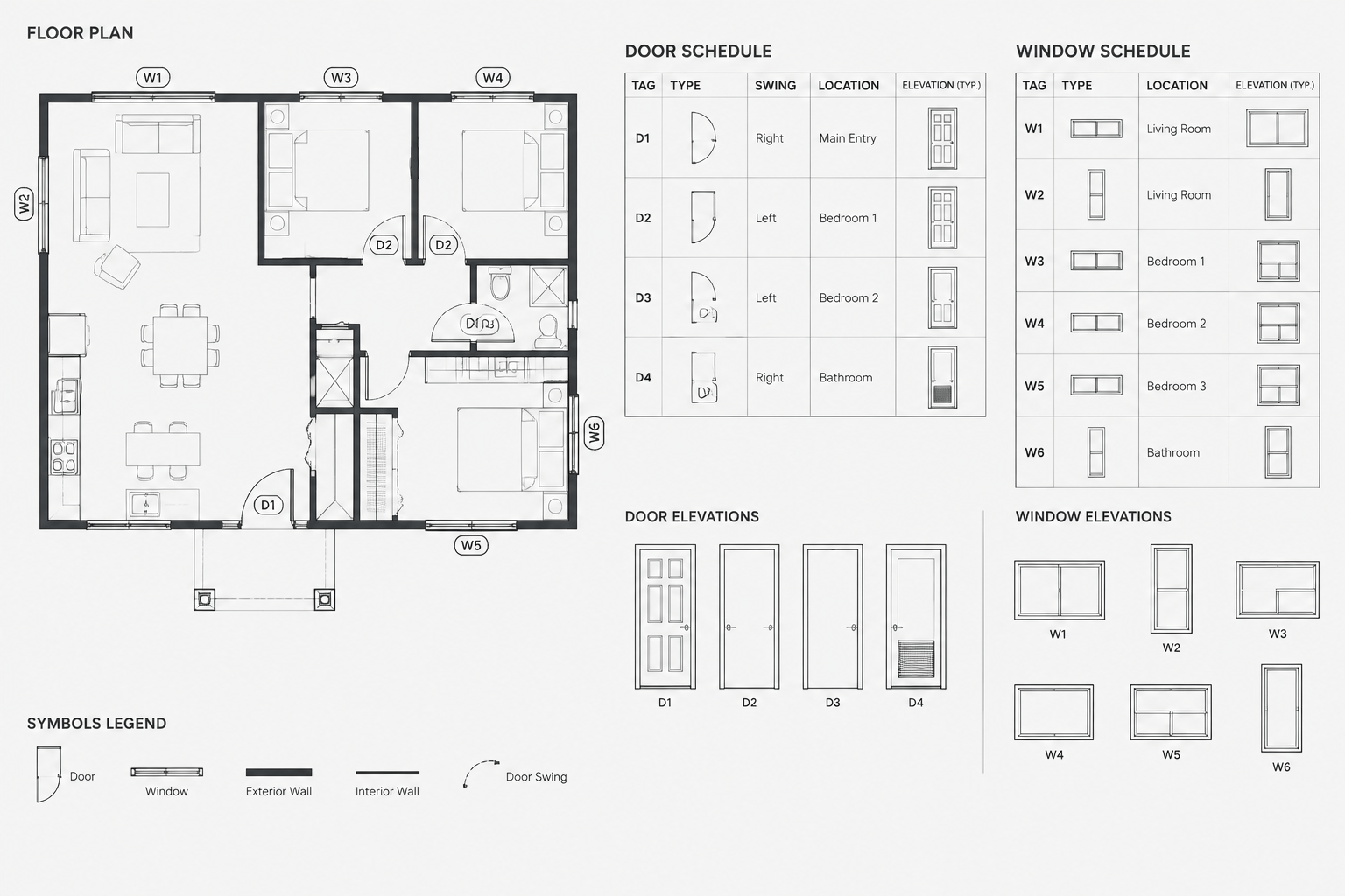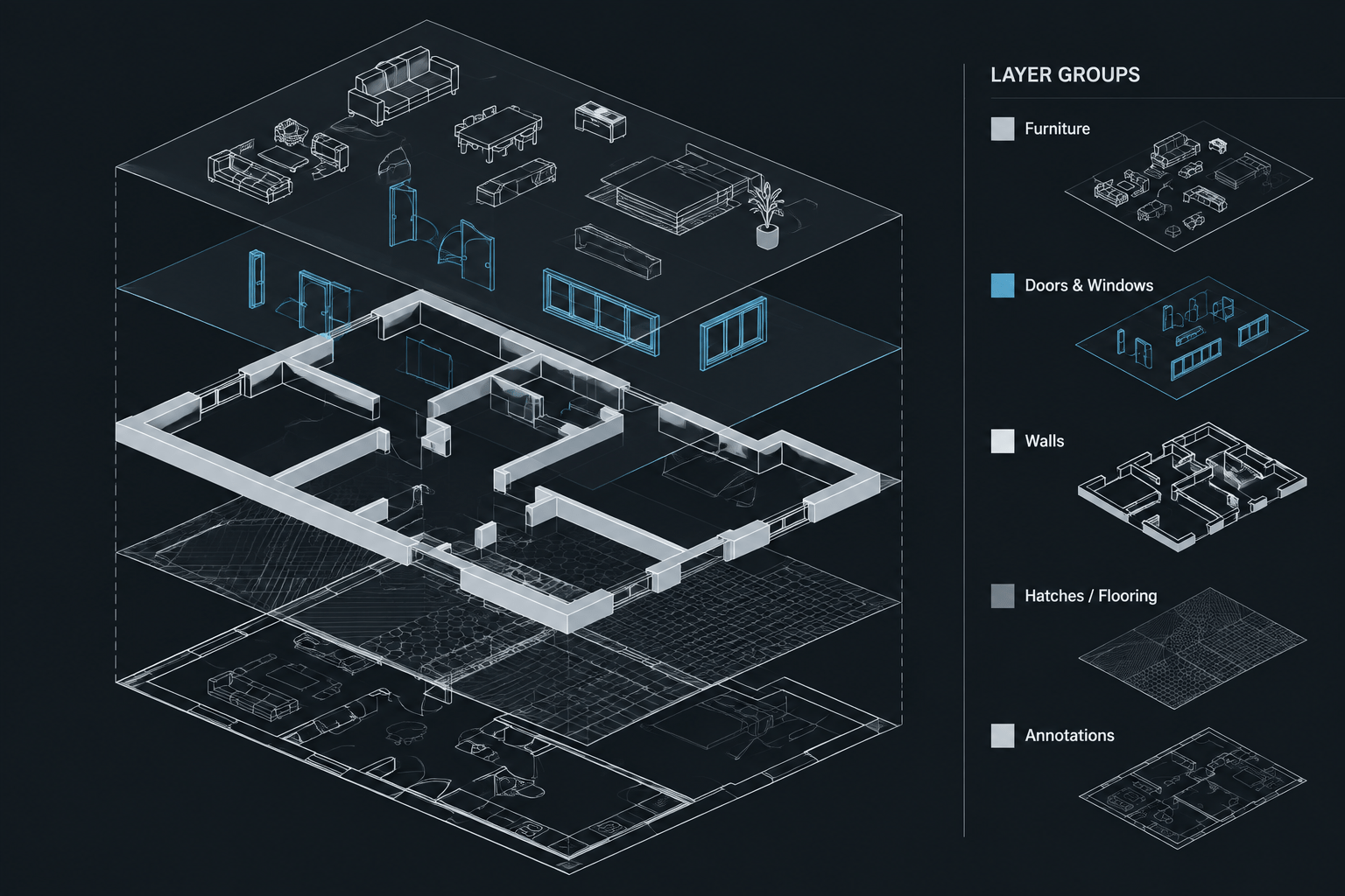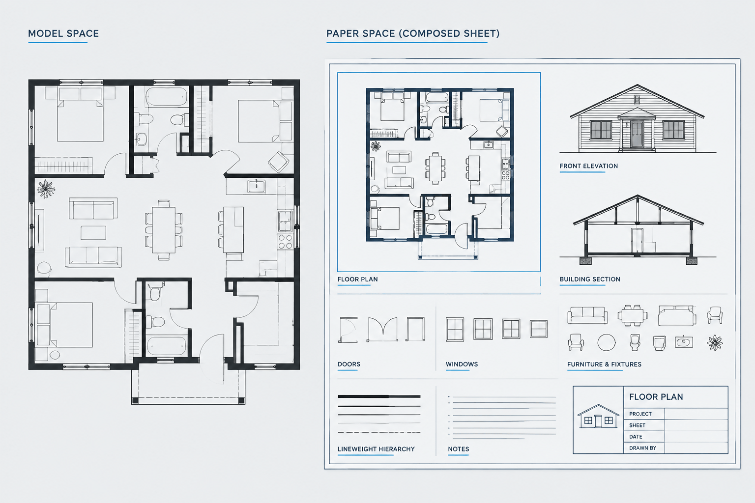
Understanding model space vs. paper space is essential for producing architectural CAD sheets that are easy to edit, coordinate, and plot. The basic distinction is straightforward: model space holds the building geometry, while paper space organizes that geometry into printable sheets. Problems arise when drawing content, notes, title blocks, and sheet graphics are placed without a consistent plan.
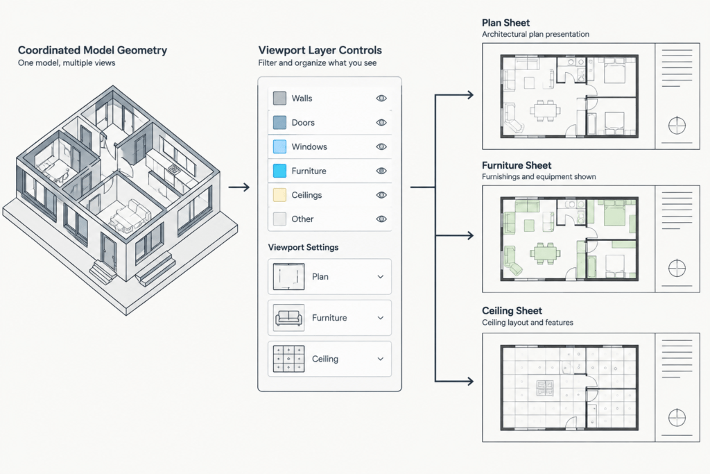
A good workflow keeps the architectural model reusable and treats each layout as a controlled view of that model. This allows one floor plan to support several sheets, such as a general plan, a dimension plan, a furniture plan, or a reflected ceiling plan, without duplicating the base geometry for every output.
What Belongs in Model Space?
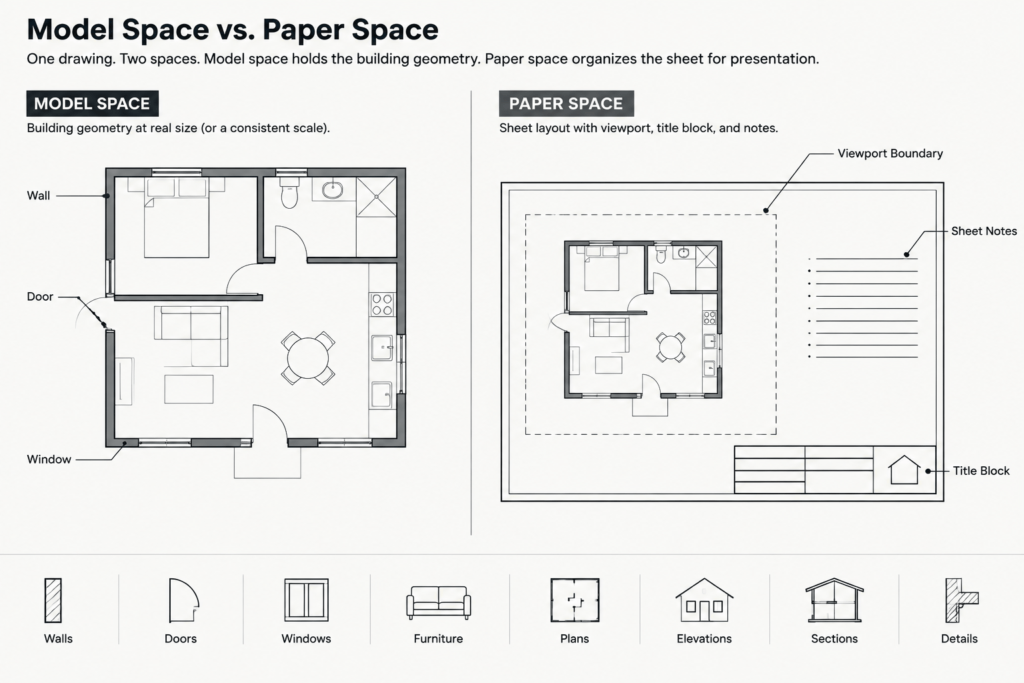
Model space is normally the working environment for full-size architectural geometry. Walls, doors, windows, stairs, fixtures, structural references, grids, and other building elements are drawn according to the project units established for the file. The geometry should represent the project rather than the final sheet composition.
Typical model-space content includes:
- Floor plans and roof plans
- Exterior and interior elevations
- Building and wall sections
- Ceiling, furniture, finish, and equipment layouts
- Referenced backgrounds from other disciplines
- Detail geometry when the office workflow keeps details in model space
- Symbols or notes intended to remain associated with model geometry
Keeping building geometry in model space makes it easier to coordinate changes. If a door moves, the relevant plan geometry can be updated in one location rather than corrected separately on several copied sheets.
What Belongs in Paper Space?
Paper space, commonly organized through layout tabs, represents the printed sheet. It is where the drafter assembles title block information, viewports, sheet-level notes, and other graphics related to presentation rather than the building model itself.
Typical paper-space content includes:
- The title block and sheet border
- Sheet number, sheet title, issue information, and project identification
- Viewports showing selected areas of model space
- General notes that apply to the complete sheet
- Legends, key plans, and sheet-specific diagrams
- Match lines or reference graphics used only for sheet composition
- Revision information when managed directly on the layout
Some offices place most annotation in model space, while others place selected notes and dimensions in paper space. Either method can work, but mixing approaches without clear rules often creates inconsistent text, duplicated callouts, and difficult revisions. Follow the project CAD standard and record any exceptions.
The Role of Viewports
A viewport is a paper-space window into model space. It does not create a separate copy of the model. Instead, it displays a chosen area, orientation, and scale. Several viewports can show different parts of the same model on one sheet or across multiple layouts.
Viewports support common architectural sheet arrangements such as:
- A main floor plan with enlarged plan areas
- Several elevations placed on one sheet
- A building section accompanied by related wall sections
- A site overview paired with a more focused entry or parking layout
- A plan with a small key plan for orientation
After setting the intended view and scale, lock the viewport if the CAD platform and office workflow support that practice. A locked viewport helps prevent accidental zooming that can change the plotted scale. Before issue, confirm the view, scale, layer display, and boundary of every viewport rather than assuming the layout remains unchanged.
Model Space and Paper Space at a Glance
| Drawing item | Usual location | Reason |
|---|---|---|
| Walls, doors, and windows | Model space | They describe the building and should remain coordinated. |
| Title block and border | Paper space | They belong to the printed sheet format. |
| Sheet identification | Paper space | It changes by layout rather than by model view. |
| Dimensions and tags | Depends on office standard | They may be model-associated or sheet-specific. |
| General sheet notes | Paper space | They apply to the assembled sheet. |
| Referenced consultant geometry | Model space | It must align with the architectural model. |
| Viewport-specific layer display | Controlled through the layout viewport | It allows one model to support different drawing purposes. |
A Step-by-Step Architectural Sheet Workflow
1. Confirm Units and Drawing Origin
Before developing sheets, confirm the file units, insertion behavior, and project origin. Referenced files need a shared positioning strategy. Moving a background manually until it appears correct may solve an immediate visual problem but can cause later coordination errors.
Check that architectural, structural, civil, and building-service backgrounds align using agreed reference points. Do not rescale consultant files merely to make them fit a sheet.
2. Organize Model Geometry
Separate building elements logically with layers or the project’s chosen classification method. Distinguish permanent geometry from overhead items, demolition work, furniture, equipment, grids, annotation, and reference files. Clear organization makes viewport-specific visibility practical later.
Remove unintended duplicates and avoid using color alone to communicate meaning. Layer names, line types, lineweights, and plotted output should work together.
3. Create or Insert the Title Block
Place the correct title block in paper space according to the intended sheet format. Confirm that the title block is not accidentally scaled, stretched, or inserted using incompatible units. Fill in project and sheet data using the office’s established method.
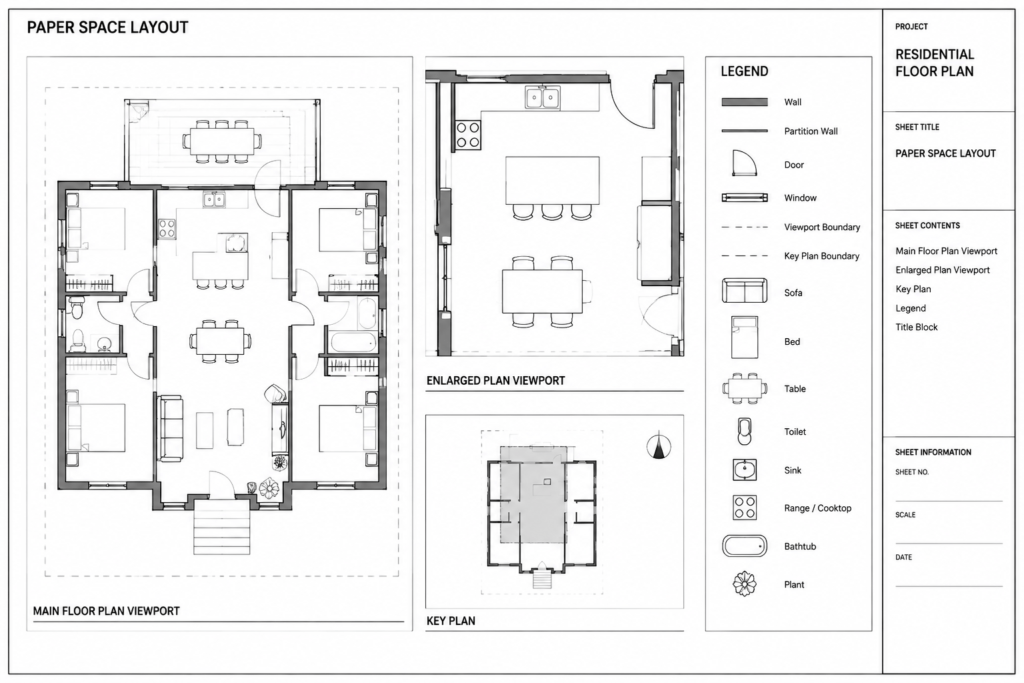
A title block should function as controlled sheet information, not as decorative linework. If attributes or fields are used, review their displayed values before plotting.
4. Create the Main Viewport
Create a viewport and navigate to the required model area. Set its scale using a deliberate method rather than approximate zooming. Position the viewport within the title block while preserving room for notes, dimensions, legends, and other views.
Use a nonplotting layer for viewport boundaries when that matches the project standard. Always verify through a plot preview, because an on-screen boundary may behave differently from the intended printed result.
5. Control Layers by Drawing Purpose
The same model can support different sheets when each viewport displays only the information needed for its purpose. A furniture plan may show movable items prominently, while a dimension plan may suppress them to keep dimension strings clear. A reflected ceiling plan may use a different combination of architectural elements and line conventions.
Viewport-specific layer controls can reduce duplicate geometry, but they also require careful checking. A hidden layer may contain an important callout, opening, or reference. Compare related sheets during quality control.
6. Add Annotation Consistently
Decide where dimensions, room names, door tags, section marks, and notes will live. If annotation is placed in model space, it must display correctly at the intended viewport scale. If it is placed in paper space, it must remain accurately aligned with the model view.
Avoid placing some instances of the same annotation type in model space and others in paper space unless there is a documented reason. Consistency makes later editing safer.
7. Check the Plotted Sheet
Do not treat a clean CAD screen as proof of a correct drawing. Review the actual sheet composition through plot preview or a test output. Check line hierarchy, text readability, viewport clipping, title block data, sheet references, and blank areas. Confirm that hidden or frozen content has not removed information required to understand the drawing.
Common Workflow Mistakes
Copying the Model for Every Sheet
Separate copies quickly drift out of coordination. Whenever possible, create different sheet views from shared model geometry and control presentation through viewports and layers.
Scaling the Building to Fit the Border
The building model should remain at full size in the chosen drawing units. Control the printed size through the viewport and sheet setup rather than scaling the architecture to fit the title block.
Leaving Viewports Unchecked
An accidental pan or zoom can alter a sheet. Confirm every viewport immediately before issue, even if it was previously locked or reviewed.
Using Paper Space to Hide Model Problems
Covering unwanted geometry with filled areas or masking objects may conceal an issue on one sheet without fixing the model. First determine whether the underlying layer, reference, or geometry should be corrected.
Ignoring Annotation Ownership
Team members need to know whether a note belongs to the model, a specific view, or the complete sheet. Unclear ownership leads to repeated labels and contradictory information.
A Practical Pre-Issue Checklist
- Confirm the model remains full size in the correct project units.
- Verify the title block and layout correspond to the intended sheet.
- Check viewport area, orientation, scale, and lock status.
- Review viewport-specific layer visibility.
- Confirm dimensions, tags, symbols, and notes match the displayed geometry.
- Inspect external references for alignment, status, and unwanted layers.
- Check sheet titles, numbers, revision information, and cross-references.
- Use plot preview to inspect lineweights, text, clipping, and page placement.
- Compare related plans, elevations, sections, and enlarged views for coordination.
Choosing a Consistent Office Method
There is no single model-space and paper-space arrangement that fits every architecture practice. Project size, consultant coordination, detail libraries, annotation methods, and deliverable requirements all influence the setup. The most important goal is consistency: building geometry should have a clear home, sheet information should be controlled, and another drafter should be able to understand the file without guessing.
A disciplined model space vs. paper space workflow reduces duplicated drafting, improves plotting reliability, and makes architectural DWG files easier to revise. Treat model space as the coordinated drawing environment and paper space as the publishing environment, then verify the connection between them on every sheet.