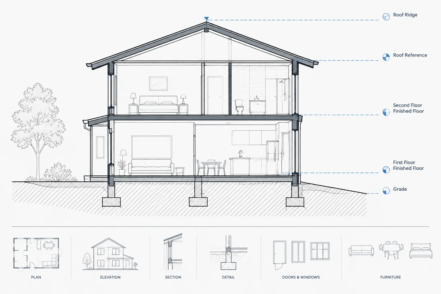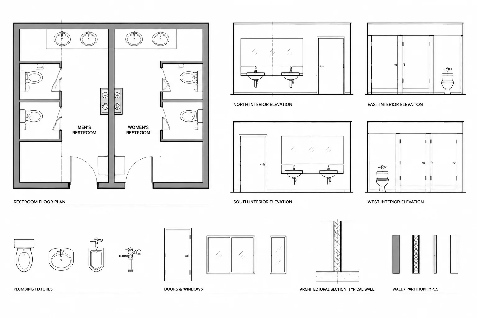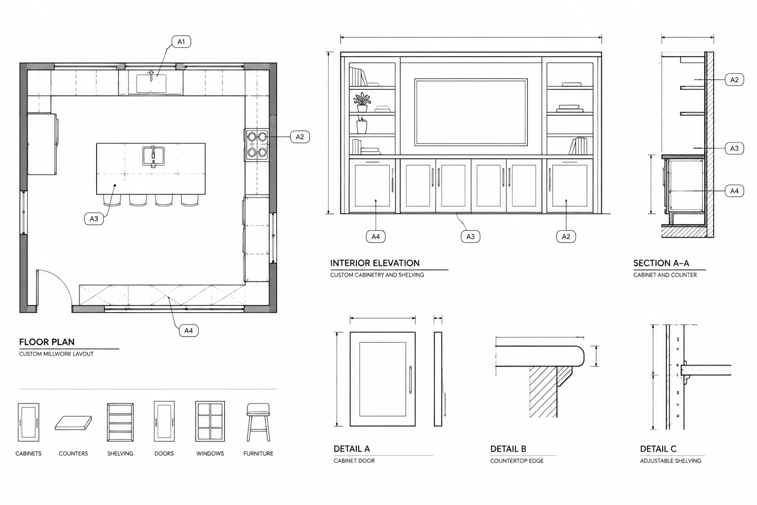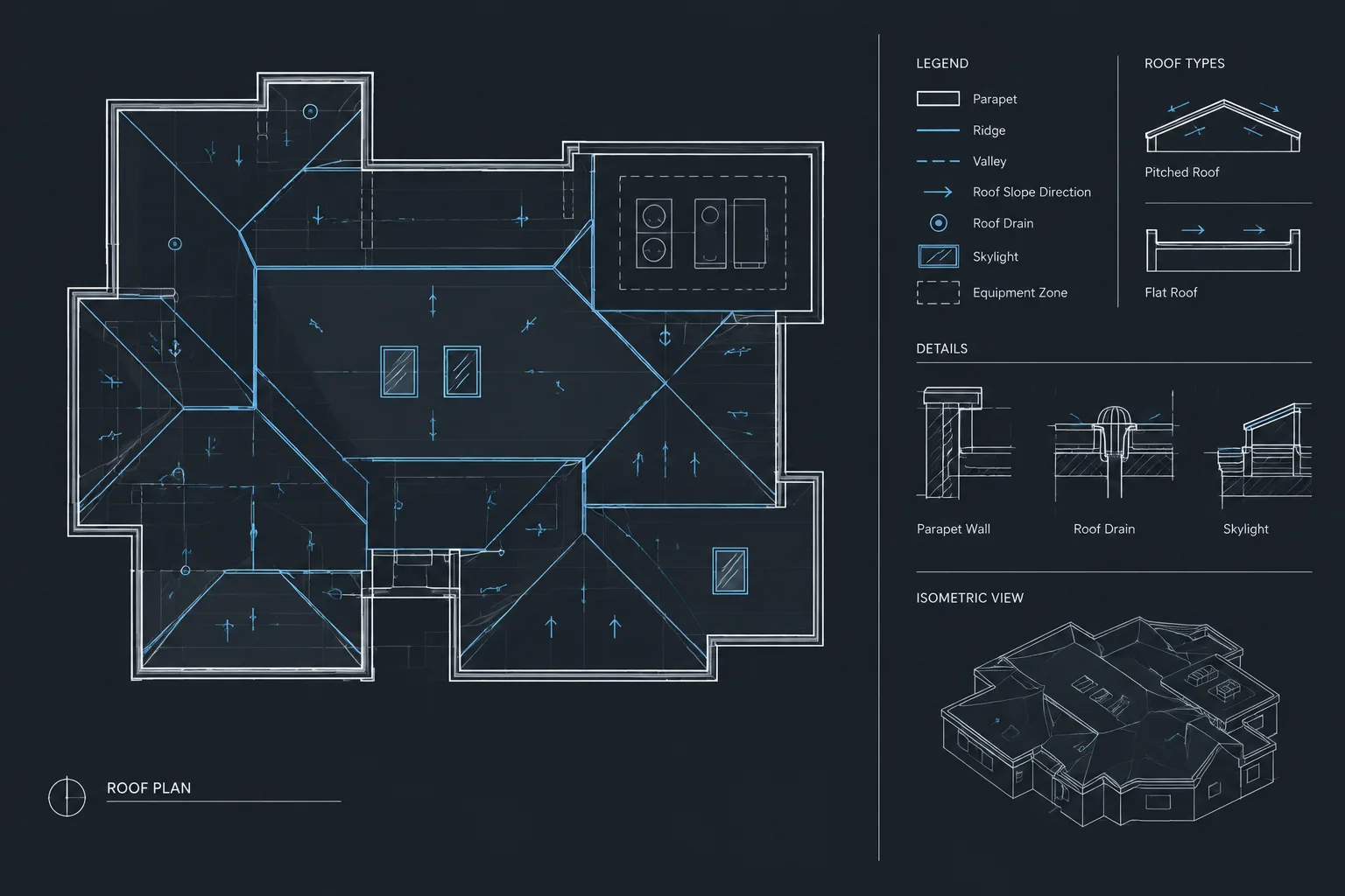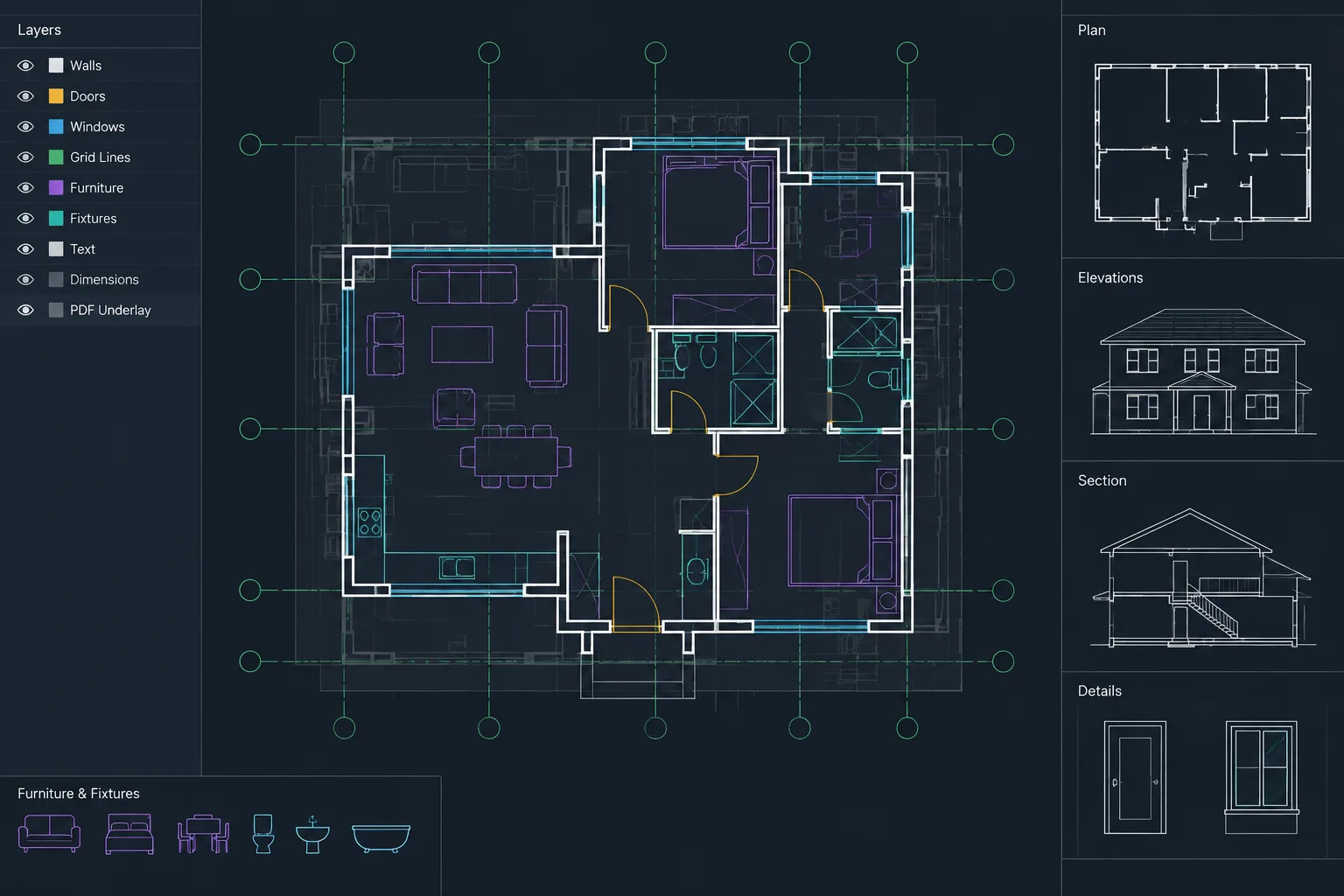
Knowing how to trace a PDF floor plan in AutoCAD involves more than drawing over visible lines. The source may be incomplete, distorted, outdated, or based on assumptions that cannot be confirmed from the sheet alone.
This guide presents a controlled workflow for evaluating the PDF, positioning it as an underlay, establishing scale, rebuilding useful architectural geometry, and documenting unresolved conditions. The objective is a clean and auditable CAD base—not a false impression of precision.
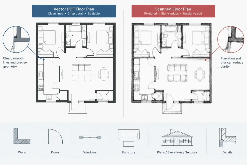
A PDF floor plan can be a useful starting point when the original DWG file is unavailable. It may contain vector linework exported from CAD, a scan of a paper drawing, or a combination of geometry and raster images. Each type requires a slightly different approach, but none should be treated as verified project geometry without checking it.
The goal is not simply to reproduce every visible line. A reliable tracing workflow identifies the source, establishes a defensible scale, separates new CAD geometry from the underlay, and records uncertainties that require field or consultant verification.
Evaluate the PDF Before Tracing
Open the PDF outside the CAD file and review the entire page. Determine whether it represents a floor plan, reflected ceiling plan, presentation plan, record drawing, or permit sheet. Similar-looking drawings may communicate different information and may not show the same wall faces, openings, or overhead elements.
Zoom closely into text and linework. Crisp geometry that remains sharp at high magnification is often vector-based. Pixelation, shadows, folded-paper marks, and uneven line quality usually indicate a scan. A vector PDF may support cleaner measurement or object snapping when used as an underlay, but that does not prove that its geometry is current or accurate.
Before starting, record the information available on the sheet:
- Drawing title and apparent purpose
- Issue date or revision information, if shown
- Original drawing scale, if identified
- Named levels, rooms, grids, or reference points
- Written dimensions that can be independently confirmed
- Areas that are cropped, obscured, or difficult to read
A PDF marked as an existing-condition drawing can still contain design assumptions. Likewise, a scanned construction sheet may have been reduced, stretched, or printed from an earlier revision.
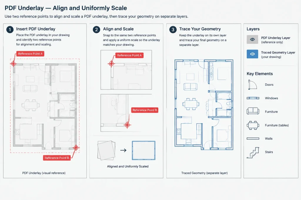
Attach the PDF as a Controlled Underlay
Keep the source PDF separate from the geometry you create. Attach it as an underlay rather than immediately converting all of its contents into editable CAD objects. This preserves a visual distinction between source information and interpreted linework.
Place the underlay on a dedicated layer with a clear name related to its source and purpose. Set the layer so it will not accidentally plot in issued drawings unless the project workflow specifically requires it. Locking the layer after positioning also helps prevent unintended movement.
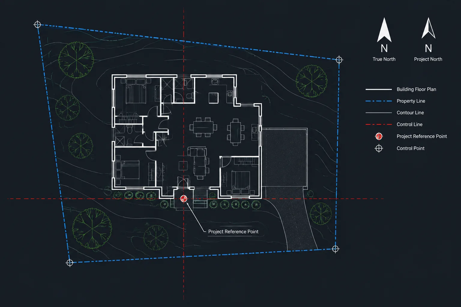
Insert the page near the project working area using a deliberate insertion point. If an established project origin exists, do not redefine it merely to accommodate the PDF. Instead, move and rotate the underlay into the project coordinate system using recognizable reference points.
Adjust underlay contrast or fading so that newly drafted geometry remains visually dominant. The source should be readable without competing with walls, doors, dimensions, and annotations.
Establish Orientation and Scale
A printed scale note is helpful, but it should not be the only basis for calibration. PDF creation, page resizing, scanning, and printing can change the relationship between page size and drawing geometry.
Choose a dependable reference
Use a clearly identified dimension between points that can be located unambiguously. Grid intersections, structural column centers, overall exterior dimensions, and other stable references are generally more useful than measuring between blurred wall edges. Avoid calibrating from furniture, door graphics, sheet borders, or graphic scale bars unless their reliability has been confirmed.
Measure the corresponding distance in the attached PDF. If it does not match the documented distance, use a uniform scale correction based on the known reference. AutoCAD workflows may use the SCALE command with a reference length, provided the selected points and stated distance are dependable.
Check more than one location
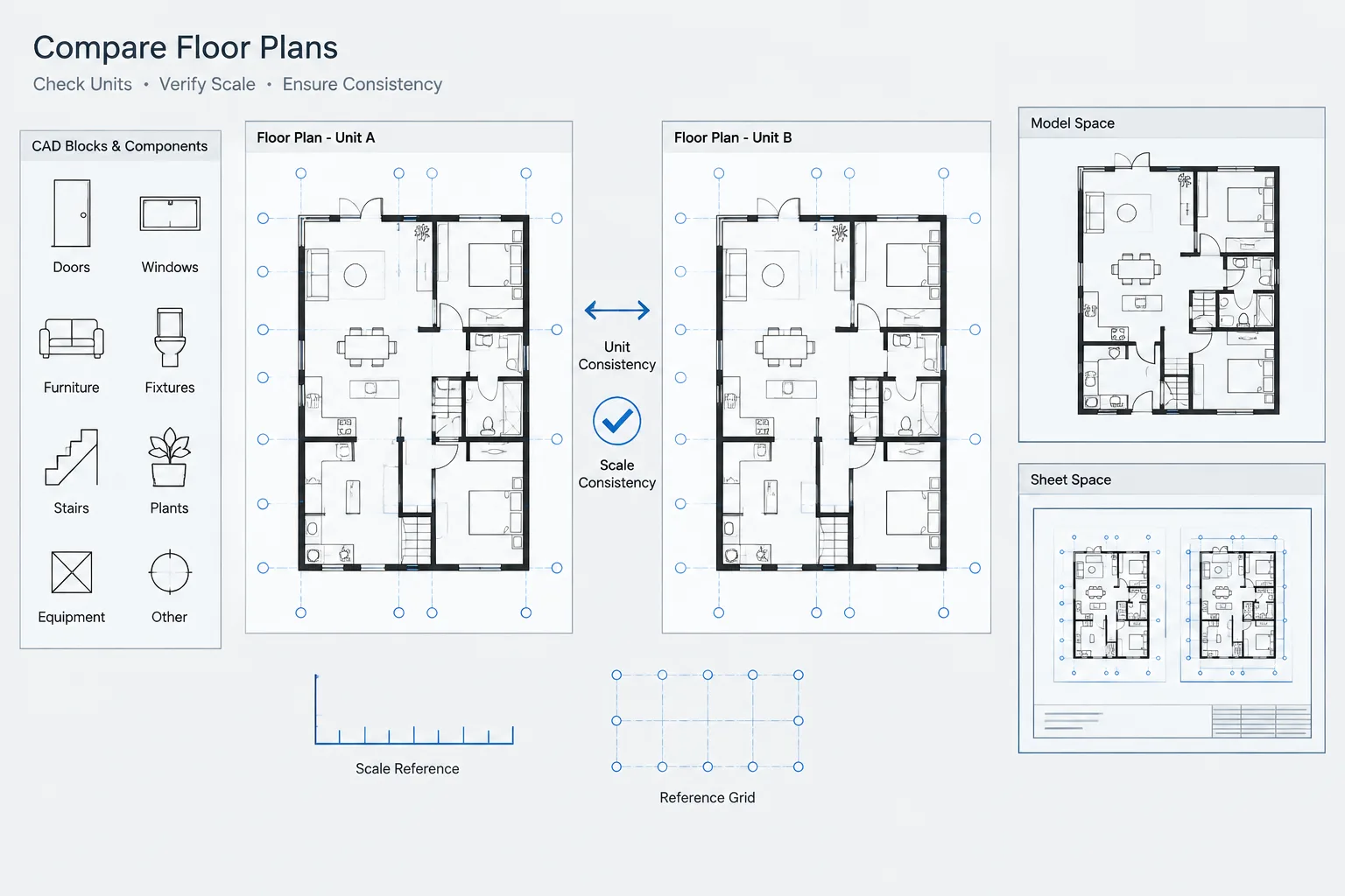
After scaling, compare additional known dimensions in different parts of the plan. A single matching distance does not establish overall accuracy. A scan may be skewed, stretched in one direction, or locally distorted.
| Observed condition | Likely implication | Recommended response |
|---|---|---|
| Several references agree closely | The underlay may be suitable as a tracing base | Continue while retaining verification notes |
| One reference matches but others do not | The source may be distorted or inconsistent | Do not force all geometry to fit; identify controlled areas |
| Horizontal and vertical references differ | The scan may have directional distortion | Request a better source or reconstruct from verified dimensions |
| No dependable dimensions are available | Scale cannot be established confidently | Use the PDF only as diagrammatic information |
Do not apply separate horizontal and vertical scaling merely to make a drawing appear correct. That can disguise source problems and produce misleading room proportions, opening widths, and alignment conditions.
Plan the Geometry You Actually Need
Tracing every mark often creates a dense and unreliable DWG. Decide what the new drawing is intended to support. An early planning base may need primary walls, columns, openings, stairs, and room boundaries. A renovation plan may also require fixed equipment, floor changes, and existing construction classifications.
Create destination layers before tracing. Separate major categories such as exterior walls, interior partitions, doors, windows, columns, stairs, fixtures, overhead elements, and source notes. Follow the project layer standard rather than copying arbitrary color or lineweight relationships from the PDF.
Determine whether walls will be represented by faces, centerlines, or another project convention. Switching methods midway through the plan creates alignment and dimensioning problems.
Trace Architectural Elements in a Logical Order
Start with stable references
Trace grids, major structural elements, exterior boundaries, and other controlling geometry first. These elements establish the framework for interior construction. Use continuous lines or polylines where appropriate, and keep corners geometrically connected rather than relying on visual overlap.
Build walls from controlling geometry
Where verified wall thicknesses are available, construct wall faces using CAD geometry rather than tracing both fuzzy edges independently. Scanned lineweights may make a wall appear thicker or thinner than intended. If wall construction is unknown, classify it as unverified instead of assigning a type based only on appearance.
Add openings and vertical circulation
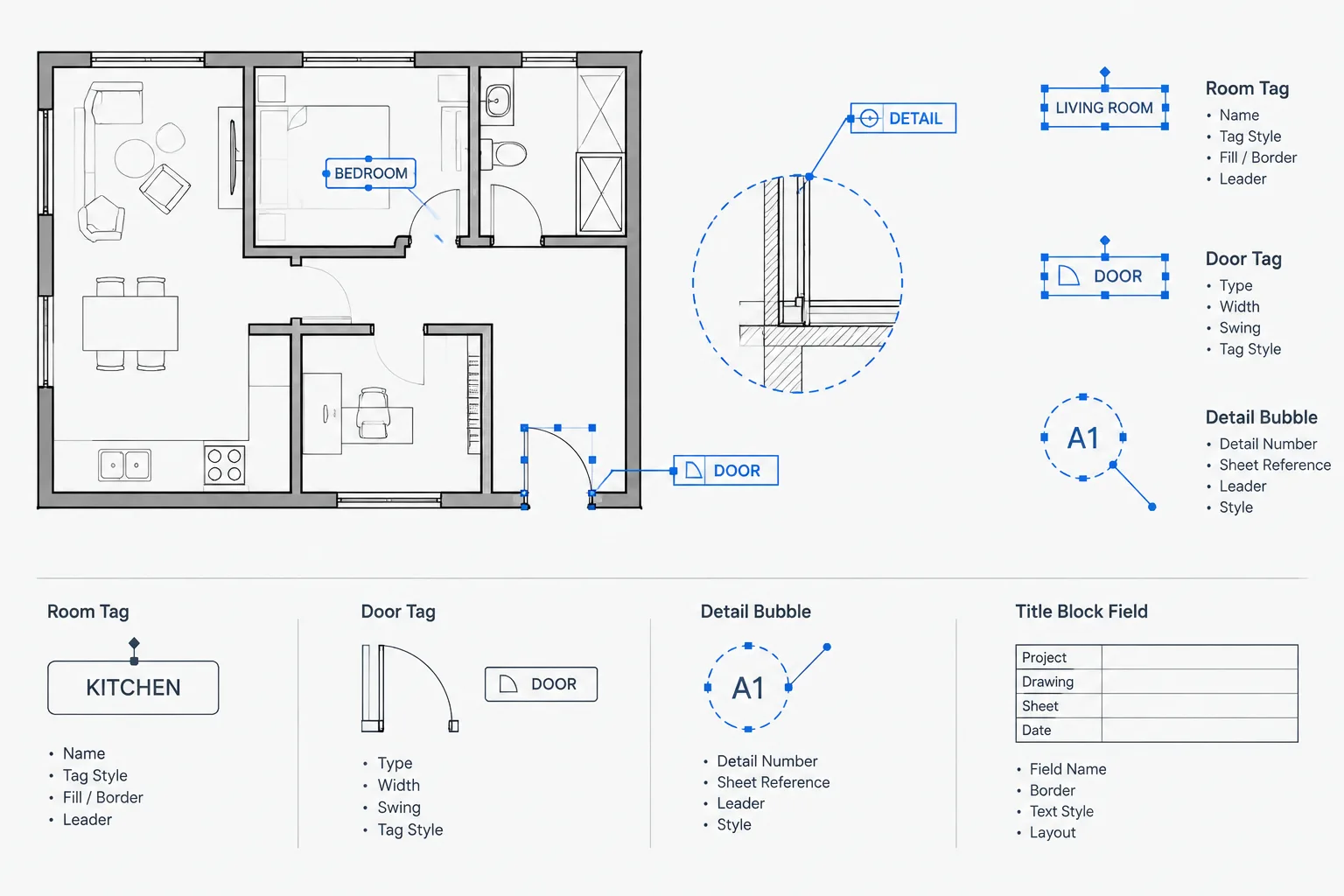
Locate doors, windows, stairs, and similar elements after the wall framework is stable. A PDF door symbol may communicate swing direction but not the exact frame, rough opening, or leaf size. Keep symbolic information separate from dimensions that must be confirmed.
Trace secondary information selectively
Furniture, fixtures, equipment, landscaping, and decorative graphics should be traced only when they serve the drawing purpose. When possible, replace rough source symbols with clean, project-standard CAD blocks. Review block scale, insertion point, layer behavior, and graphic detail before use.
Handle Vector PDF Geometry Carefully
Importing vector PDF content can save time, but it can also produce fragmented line segments, repeated objects, filled regions, inconsistent text, and unnecessary layers. Imported geometry should be treated as raw source material rather than finished architectural linework.
If importing is useful, test a limited area first. Examine whether walls become continuous objects, curves remain usable, and text is recognizable. Compare the cleanup effort with manual reconstruction. For a small or irregular plan, controlled tracing may be faster and more reliable than repairing thousands of imported objects.
Keep imported source geometry in a separate working file or isolated layer group until it has been reviewed. Do not merge it directly into established project layers before cleanup.
Verify the Completed Trace
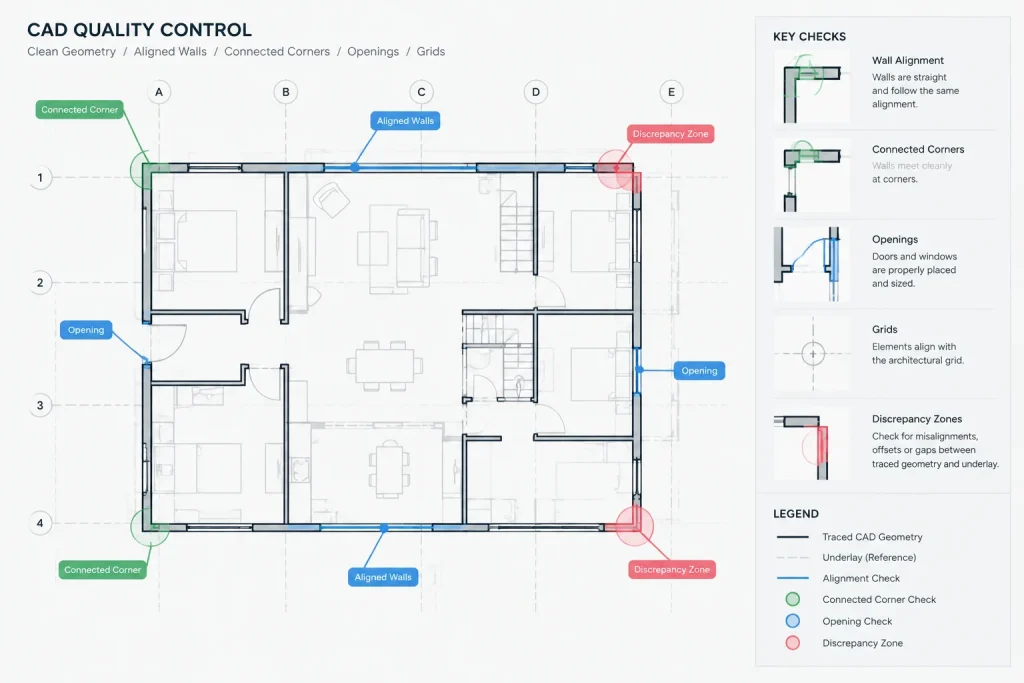
Once the principal geometry is drafted, temporarily change the underlay display so discrepancies are easy to see. Review the plan systematically rather than relying on a general visual impression.
- Compare overall building extents and major offsets.
- Check grid, column, and wall alignments.
- Confirm that wall corners close cleanly.
- Review door and window locations against adjacent dimensions.
- Check stairs, shafts, and floor openings across related levels.
- Look for duplicated lines and short fragments.
- Confirm that overhead or hidden elements use the correct graphic convention.
- Review room boundaries for gaps or overlaps.
Measure the new CAD geometry using several independent references. Dimensions placed in the new drawing should report the drafted geometry; they should not be overwritten to reproduce labels from the PDF.
Document Assumptions and Source Limitations
A traced plan should communicate its level of reliability. Keep a brief source record in the project notes or file documentation. Identify the PDF used, its apparent issue information, the calibration reference, and any areas that did not reconcile.
Use clear internal notes for conditions such as wall location to be verified, opening size unclear, or geometry reconstructed from partial information. These notes can remain on nonplotting coordination layers until the questions are resolved.
For work involving existing buildings, a PDF trace is not a substitute for field verification, a current survey, or appropriate consultant information. Life-safety conditions, accessibility clearances, structural elements, and concealed construction require project-specific review.
Final CAD Cleanup
Before using the traced plan as a project background, remove temporary construction geometry, resolve duplicate objects, and confirm that all elements are on intentional layers. Check that line types display appropriately and that the drawing plots legibly at its intended sheet scale.
Retain the original underlay in a controlled location rather than deleting the audit trail. A clean, verified trace is most useful when future users can understand where it came from, what was confirmed, and what remains uncertain.
Decide When the Trace Is Ready for Use
A visually clean drawing is not automatically a dependable background. Before handing off the file, separate questions about CAD quality from questions about source reliability. Lines may be connected, layered, and easy to edit while the represented building conditions remain unconfirmed.
Review the CAD file itself
- Confirm that the PDF underlay and reconstructed geometry remain visually distinguishable.
- Check that major architectural elements follow the intended layer and graphic conventions.
- Remove accidental fragments, overlaps, duplicate objects, and abandoned construction lines.
- Verify that walls, openings, stairs, columns, and room boundaries relate consistently.
- Confirm that the underlay has not shifted or rotated after calibration.
Review the reliability of the information
- Identify which geometry was established from written dimensions or stable references.
- Mark areas interpreted from blurred, cropped, or conflicting source information.
- Distinguish confirmed geometry from approximate symbolic content.
- Record discrepancies that cannot be resolved from the PDF.
- State where field checks, surveys, or consultant information are still required.
The resulting DWG should allow another user to understand both what was drawn and why it was drawn that way. Preserving the underlay, calibration basis, and verification notes makes later revisions easier to evaluate and reduces the risk that assumptions will be mistaken for measured conditions.
Frequently Asked Questions
Can a PDF floor plan be considered accurate after it is scaled in AutoCAD?
No. Scaling can make a selected reference agree with a documented distance, but it does not prove that the rest of the page is undistorted, current, or dimensionally consistent. Additional references should be checked across the plan.
Is it better to import PDF geometry or trace the underlay manually?
It depends on the source. Clean vector content may reduce initial drafting, but imported objects can be fragmented or poorly organized. A scanned or irregular source is often better reconstructed selectively using controlled CAD geometry. Test the source before committing to either workflow.
Should CAD objects be snapped directly to a vector PDF?
Vector underlays may provide usable snap locations, but those points still inherit any errors in the source. Use them as drafting aids only after checking orientation, scale, and reference reliability.
What should be done when dimensions on the PDF conflict?
Do not distort the entire trace to satisfy incompatible information. Preserve the dependable controlling references, identify the affected area, and document the conflict for further verification.
Should both edges of a scanned wall be traced?
Not automatically. Heavy or blurred source lines may not represent exact wall faces. Where dependable construction information is available, build the wall from controlling geometry. Otherwise, record the wall location or construction as unverified.
Why retain the original PDF underlay after tracing?
The underlay provides an audit trail. It helps future users compare the reconstructed geometry with the source, understand calibration decisions, and review unresolved discrepancies.