Architectural notes explain information that linework alone cannot communicate clearly. They identify materials, describe installation intent, call attention to project conditions, and connect drawing locations with schedules or specifications. Without a consistent note system, however, sheets can become crowded, repetitive, and difficult to coordinate.
A practical CAD workflow separates general instructions from location-specific notes and gives every annotation a clear relationship to the drawing. The objective is not to place as much text as possible. It is to provide the right information at the right level, in a form that remains readable and manageable as the project changes.
Understand the Main Types of Architectural Notes
Before drafting, decide what kind of note each piece of information should become. Different note types serve different purposes and should not be used interchangeably.
| Note type | Typical purpose | Drawing relationship |
|---|---|---|
| General note | Communicates broad instructions or drawing conventions | Applies to a sheet, discipline, drawing group, or project area |
| Keynote | Connects a short identifier to a longer description | Points to a specific object, assembly, or condition |
| Direct note | Places a concise description beside an item | Usually connected with a leader or positioned immediately nearby |
| Reference note | Directs the reader to another view, detail, schedule, or document section | Supports navigation rather than describing the complete condition |
| Sheet note | Provides instructions relevant to one sheet | Placed in a dedicated notes area within the sheet composition |
A statement that applies throughout a plan should not be repeated with leaders at many individual locations. Conversely, a unique construction condition should not be hidden in a broad general-note paragraph. Classifying notes correctly reduces clutter and makes their scope easier to understand.
Choose Between Keynotes and Direct Notes
A direct note displays its description beside the referenced element. This is useful when the text is short, the drawing has enough open space, and the instruction is unlikely to appear many times. Readers can understand it without searching elsewhere on the sheet.
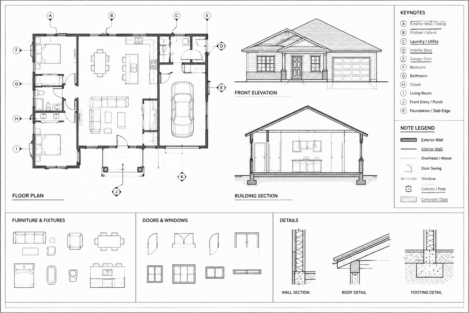
A keynote replaces the full description with a compact identifier. That identifier corresponds to an entry in a legend or note list. Keynotes are helpful when descriptions repeat, annotation space is limited, or a coordinated set of descriptions must be maintained across several views.
Keynotes are not automatically better simply because they are compact. Excessive use can force readers to move repeatedly between the drawing and a long legend. Use them where the reduction in repetition and clutter outweighs the extra lookup step.
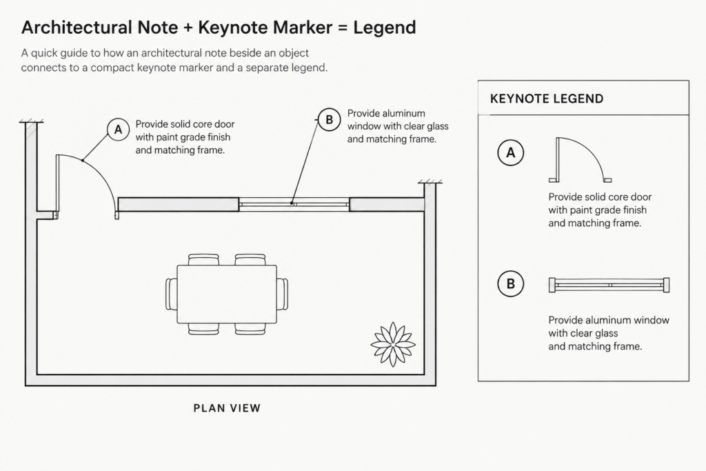
A useful decision test
- Use a direct note when a short description can be read comfortably at the point of use.
- Use a keynote when the same description appears in several locations.
- Use a general note when the instruction truly applies to the entire stated scope.
- Use a schedule or specification reference when the information belongs in a structured data source rather than in drawing text.
- Avoid placing important location-specific requirements only in a remote notes panel.
Build a Controlled Keynote List
A keynote list should function as a controlled project resource, not as a collection of unrelated phrases copied from older drawings. Begin with only the notes required for the current project and add entries as drawing conditions are developed.
Each identifier should correspond to one clear description. Avoid reusing the same identifier for different meanings, even when those meanings appear on separate sheets. If an entry changes meaning, update both the legend and every associated marker through a deliberate coordination process.
Choose an identifier structure that can be sorted and checked easily. The structure may group notes by subject, assembly, drawing category, or another office convention. The particular system matters less than consistency and documented use. Do not make an identifier so complex that drafters must decode it before placing a note.
Write keynote descriptions in parallel language. Similar entries should use a similar order, such as identifying the element first and then stating the required action or reference. Remove vague phrases that depend on unstated assumptions. A note should tell the reader what the marker identifies without attempting to replace necessary details, schedules, or project specifications.
Create a Consistent CAD Annotation System
Keynote markers, text, leaders, and legends should share a coordinated graphic standard. Set them up using the project’s approved text styles, leader conventions, layers, and plotting hierarchy. The resulting annotation should remain legible at the sheet’s intended plotted scale.
Keep the following components consistent:
- Marker shape: Use a recognizable enclosure or label format that is distinct from door tags, room tags, detail references, and revision markers.
- Text appearance: Apply a consistent font, plotted height, width behavior, and capitalization convention.
- Leader appearance: Coordinate arrowheads, landing behavior, and lineweight with other annotations.
- Layer assignment: Separate keynote graphics from model geometry so annotation can be managed and plotted predictably.
- Legend formatting: Align identifiers and descriptions in a readable column structure with controlled wrapping.
If reusable CAD blocks are used for markers, keep their insertion point logical and verify that identifier text remains centered when edited. A marker should not contain unrelated project information or leave behind invisible geometry, duplicate attributes, or unnecessary layers.
Place Leaders Without Obscuring the Drawing
A keynote is useful only when its target is unmistakable. Point the leader to the object edge, material region, joint, or other condition being described. Avoid ending a leader in open space where it could refer to several nearby elements.
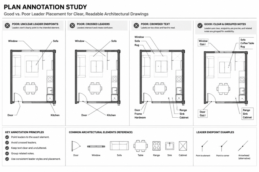
Arrange notes in orderly groups where practical, but do not stretch leaders across large portions of a plan merely to create a perfectly aligned column. Long leaders are difficult to trace and are more likely to cross dimensions, walls, grids, or other annotations.
Use bends sparingly and prevent leader lines from running through text. When several leaders cross, adjust note placement or divide the group. If one note applies to multiple clearly related locations, multiple leaders may be appropriate, but separate markers can be easier to track when the locations are far apart.
Review leader placement at the intended sheet scale rather than relying only on a close model-space view. What looks clear while zoomed in may become a dense knot of lines on the plotted sheet.
Coordinate Notes Across Plans, Elevations, and Sections
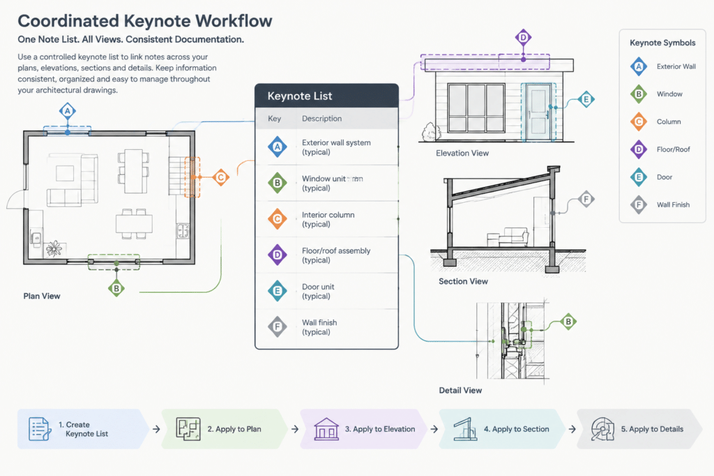
The same assembly may appear in a floor plan, interior elevation, building section, and detail. Notes in these views should complement one another rather than provide conflicting instructions.
Assign information to the view where it is most clearly represented. A plan may identify the location of an element, while an elevation describes its vertical extent and a detail explains its interfaces. Repeating the complete instruction in every view increases the chance that one instance will remain outdated after a revision.
When similar keynotes occur on different sheets, determine whether the legend is sheet-specific or shared. A sheet-specific legend should contain only identifiers used on that sheet unless the drawing set establishes another clear convention. A shared legend can reduce repetition, but it requires tighter project-wide control and straightforward navigation.
Separate Notes from Dimensions and Tags
Notes should not compete with dimensions, room names, wall tags, door identifiers, or section symbols. Establish annotation zones where possible and maintain visible separation between different information types.
Do not use a note to replace a dimension when a measured relationship must be shown graphically. Likewise, avoid embedding long construction instructions inside room tags or other symbols intended for identification. Each annotation system should perform a distinct job.
When a drawing becomes crowded, consider whether the view needs an enlargement, a separate detail, or a schedule instead of simply reducing text or compressing leader spacing. Readability should be resolved through drawing organization, not by making critical information difficult to see.
Run a Keynote Coordination Check
Keynotes require a dedicated review before issue. A general visual inspection may not reveal unused legend entries, duplicate identifiers, or markers whose descriptions have changed.
Recommended review sequence
- Compare every visible marker with the applicable keynote legend.
- Confirm that each identifier has one current description.
- Remove legend entries that are not used when the project convention calls for sheet-specific lists.
- Look for copied markers that still reference an unrelated condition.
- Check that leaders terminate at the intended objects.
- Review note scope words so readers can tell where each instruction applies.
- Compare repeated assemblies across plans, elevations, sections, and details.
- Plot or preview the sheet to evaluate wrapping, line spacing, and graphic density.
Recheck the system after major revisions. Moving walls, changing finishes, replacing components, or deleting details can leave valid-looking markers attached to obsolete conditions.
Treat Notes as Coordinated Drawing Data
Architectural notes are not decorative labels added after the design is complete. They are coordinated project information and should be managed with the same care as dimensions, schedules, and references.
A successful CAD note system uses direct notes for immediate clarity, keynotes for controlled repetition, and general notes only for genuinely broad instructions. Clear identifiers, disciplined leader placement, and routine cross-sheet checks help the drawing set communicate intent without unnecessary clutter. Before relying on any note for a real project, verify its wording and scope against the current design, project documentation, applicable requirements, and responsible professional review.