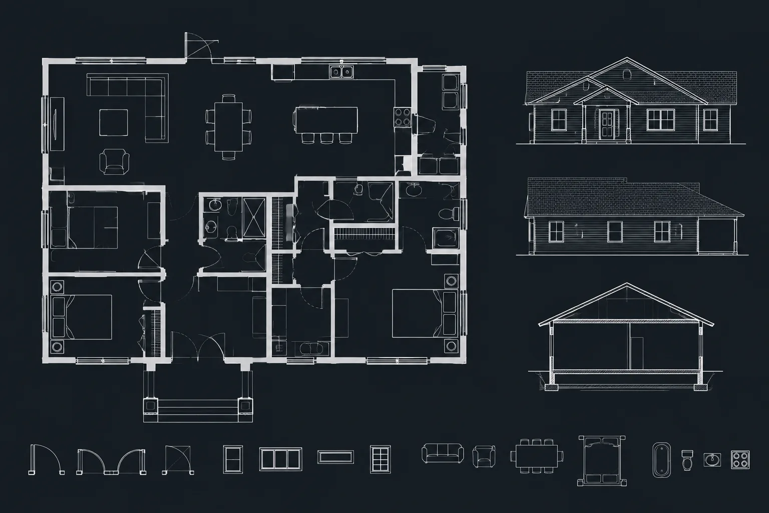
Learning how to draw walls in AutoCAD is less about producing parallel lines and more about creating dependable architectural geometry. Each wall face should have a clear meaning, connect accurately at junctions, and remain coordinated with openings, dimensions, room boundaries, and related views.
The workflow below treats walls as part of an interconnected floor plan rather than isolated linework. It helps CAD users choose controlling geometry, organize layers, form clean intersections, and review revisions before the drawing is issued or shared.
Walls may look simple on a finished floor plan, but they control much of the drawing’s geometry. Inconsistent thicknesses, overlapping corners, accidental gaps, and poorly coordinated openings can affect dimensions, room areas, door locations, elevations, and details. A reliable wall-drafting method therefore needs to do more than produce two parallel lines.
This guide explains how to draw walls in AutoCAD using a practical two-dimensional workflow. It focuses on clean geometry and architectural coordination rather than a particular office standard. Before using any wall thickness or assembly in a real project, confirm the design intent, construction type, consultant requirements, and applicable regulations.
Choose What the Wall Lines Represent
Before drawing, decide what each line means. Depending on the drawing and project phase, wall lines might represent finished faces, framing faces, structural boundaries, or a simplified overall assembly. Mixing these interpretations in one plan creates subtle coordination errors.
For a typical architectural floor plan, drawing the visible finished faces is often practical because dimensions, room boundaries, fixtures, and door openings commonly relate to those surfaces. Structural or framing information can be shown separately when the drawing requires it.
Record the chosen convention in the project’s drafting notes or CAD standards. A future editor should not have to infer whether a line represents finish, substrate, or structure.
Set Up Wall Layers Before Drafting
A dedicated wall-layer structure makes the plan easier to edit, display, and plot. The exact names should follow the project or office standard, but different graphic purposes should remain distinguishable.
| Layer purpose | Typical content | Coordination benefit |
|---|---|---|
| Primary wall outlines | Wall faces cut by the plan | Supports a strong plan hierarchy |
| Overhead or beyond elements | Walls, ledges, or features outside the main cut condition | Prevents overhead information from reading as cut work |
| Wall hatches or poché | Material graphics and cut fills | Allows fills to be controlled independently |
| Existing, demolition, or new work | Geometry assigned by project status | Supports phased views and renovation drawings |
| Annotations | Wall tags, notes, and references | Keeps labels separate from physical geometry |
Avoid placing permanent wall geometry on temporary construction layers. Also avoid using color alone to communicate wall status, since colors may change between editing and plotting environments.
Select a Wall-Drawing Method
Centerline-first method
In the centerline-first method, draw a continuous control line and offset it to create the wall faces. This is useful when the plan is organized around grids, structural axes, or symmetric assemblies.
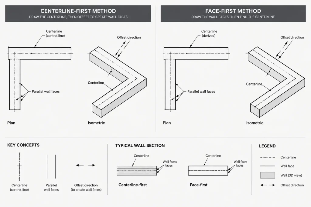
- Draw the controlling path with lines or polylines.
- Confirm that corners and intersections meet accurately.
- Offset the path according to the verified wall assembly.
- Trim, extend, or otherwise clean the resulting faces.
- Remove or relocate the control geometry if it is not part of the issued drawing.
The main risk is assuming every wall is centered on its control line. Changes in finish, shaft construction, structural alignment, or exterior buildup may require one face to remain fixed while the other changes.
Face-first method
With the face-first method, draw the most important wall face first and offset from it. The controlling face might align with a corridor, room boundary, exterior plane, or existing construction.
This approach is helpful when clear room geometry or alignment with an existing surface matters more than symmetry. Clearly identify which face is controlling so later edits do not shift the wrong side of the wall.
Closed-outline method
Walls can also be constructed as closed outlines. Closed polylines can be useful for hatching and boundary checks, but a separate closed shape for every wall segment may become cumbersome at intersections and openings. Use this method only when its boundary-management advantages fit the intended workflow.
Build the Main Wall Network Before Openings
Start with the major wall layout rather than inserting doors and windows immediately. Establish exterior limits, primary circulation, shafts, service zones, and major room divisions first. This creates a stable framework against which openings can be checked.
Use object snaps and coordinate input rather than relying on visual placement. Zooming in does not guarantee that two endpoints actually meet. Small gaps and overlaps may remain invisible at normal viewing scales but cause trouble when creating hatches, measuring areas, or generating detail geometry.
Keep construction lines separate from final wall faces. Temporary diagonals, projection lines, and planning grids are useful, but they should be easy to hide or remove before issue.
Clean Up Wall Corners Intentionally
Every corner should describe a deliberate construction relationship. Do not treat corner cleanup as a purely cosmetic task.
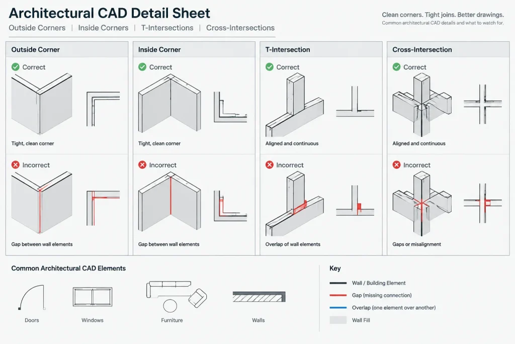
Outside corners
Extend the relevant wall faces until they meet, then remove excess geometry. Check that the resulting corner reflects the intended outside envelope. Parallel lines that stop just short of the corner can leave an open boundary even if the gap is difficult to see.
Inside corners
Inside corners often accumulate overlapping segments. Trim redundant lines and confirm that the room-side faces form a clear boundary. This matters when the plan will be used for area calculations, finish layouts, or interior elevations.
T-intersections and cross-intersections
At a T-intersection, determine whether the terminating wall meets a continuous wall face or whether the assemblies interlock in another way. At cross-intersections, avoid leaving every original line running through the junction. The finished geometry should communicate which boundaries continue and which stop.
Commands such as TRIM, EXTEND, FILLET with an appropriate project setting, and grip editing can help form corners. Regardless of the command used, inspect the result instead of assuming the operation created the intended junction.
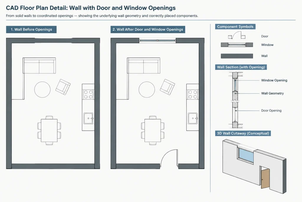
Create Door and Window Openings Without Damaging the Wall
Openings should be derived from coordinated locations rather than cut approximately around a block. Establish the opening limits, break or trim both wall faces consistently, and then place the door or window representation.
- Confirm which part of the component controls the opening.
- Align both sides of the wall opening.
- Check the component’s insertion point, orientation, and scale.
- Verify that the symbol does not merely conceal uncut wall lines.
- Review the opening in plan together with related elevations and schedules.
A block containing a background mask or solid fill can make an incorrect opening appear acceptable on screen. Temporarily hide the block or change the display order to inspect the underlying wall geometry.
Handle Changes in Wall Thickness Carefully
A wall may change because of structure, finish buildup, a pilaster, a chase, or a transition between assemblies. Do not simply offset both faces from a new centerline unless that matches the design intent.
Identify the controlling face at the transition. One side may need to remain aligned while the opposite side steps. Draft the step or taper explicitly, and coordinate it with nearby doors, built-in elements, finishes, dimensions, and room boundaries.
Wall thickness should come from verified project information. A downloaded detail or block may illustrate a useful drafting pattern, but it does not establish the correct assembly for another project.
Use Hatches and Poché as Supporting Graphics
Apply wall hatches or poché after the main boundaries are stable. Keeping fills separate from wall outlines makes revisions easier and reduces the chance that a hatch boundary will be mistaken for physical geometry.
If a hatch fails or leaks into an adjacent area, investigate the boundary rather than drawing arbitrary cover lines. Common causes include open corners, duplicate segments, tiny offsets, or an opening that was not cut through both wall faces.
Coordinate Walls with the Rest of the Drawing Set
Wall geometry is shared information. A change in plan can affect exterior elevations, interior elevations, sections, reflected ceiling plans, finish plans, furniture layouts, door and window schedules, and consultant backgrounds.
Before considering a wall revision complete, review:
- Room dimensions and circulation relationships
- Door and window locations
- Columns, shafts, and major penetrations
- Cabinetry, plumbing fixtures, and fixed equipment
- Ceiling edges, soffits, and overhead features
- Wall tags and detail references
- Related plan, elevation, and section geometry
Run a Wall Geometry Quality-Control Pass
Inspect the plan at both overall and close-up scales. An overall review reveals inconsistent alignments and unintended shifts; a close review reveals gaps, doubled lines, and incomplete intersections.
- Is each wall on the correct layer?
- Are parallel faces based on a verified assembly?
- Do corners close cleanly?
- Are duplicate and overlapping lines removed?
- Are openings cut through all required wall faces?
- Do blocks conceal any incorrect geometry?
- Are hatches contained by intentional boundaries?
- Do wall changes agree with elevations, sections, and schedules?
- Are temporary construction objects removed or isolated?
A clean wall plan is not defined only by its appearance. Its lines should carry a consistent meaning, form dependable boundaries, and remain easy to revise. Establishing the controlling geometry first, cleaning junctions deliberately, and coordinating openings after the wall network is stable produces a DWG that is more reliable throughout the drawing set.
A Practical Sequence for Revising Existing Wall Plans
Editing an established floor plan requires a different approach from drawing walls on a blank file. Before moving a wall, determine which face controls the layout and identify every object that depends on it. Dimensions, room boundaries, door blocks, hatches, fixtures, tags, and reference geometry may all require coordinated changes.
Trace the dependency before editing
Select or inspect the wall geometry and nearby objects before making the revision. Determine whether the wall was created from separate lines, connected polylines, closed boundaries, or another project-specific method. Also check whether apparently continuous geometry is divided into short segments at openings or intersections.
Edit the controlling face first
Move or redraw the face that must maintain the intended architectural alignment. Reconstruct the opposite face from verified project information rather than stretching both sides by eye. This reduces the risk of changing a corridor edge, room boundary, exterior plane, or fixed construction line unintentionally.
Rebuild affected junctions
After changing the wall position, revisit every connected corner and intersection. A stretch or grip edit may leave short remnants, overlapping segments, or disconnected endpoints. Clean the geometry so the revised junction communicates the intended relationship instead of preserving obsolete lines.
Recheck openings and attached elements
Doors, windows, casework, plumbing fixtures, and annotation may appear to move with a wall while their underlying relationships remain incorrect. Inspect insertion points, opening cuts, clearances, dimensions, and tags independently. Do not rely only on the visual appearance of blocks.
Troubleshooting Wall Geometry
A hatch crosses into another room
Look for an open endpoint, an opening cut through only one wall face, or a small offset at a corner. Repair the physical boundary instead of masking the leak with unrelated linework.
A corner looks heavy when plotted
Overlapping or duplicate wall segments may be occupying the same location. Inspect the junction closely, remove redundant objects, and confirm that the remaining lines belong on the intended layer.
A wall appears aligned but will not form a boundary
Visual alignment does not prove that endpoints share the same coordinate. Use object snaps and geometry inspection to confirm that the objects meet. Also check whether a short segment, hidden object, or elevation difference is interfering with the boundary.
A door block hides wall lines
Temporarily move, hide, or send the block behind the wall geometry for inspection. Both wall faces should contain a deliberate opening; a mask inside the block should not be the only reason the doorway looks clear.
Make Wall Revisions Easy to Audit
A reviewer should be able to distinguish permanent walls, temporary construction geometry, overhead information, hatches, and annotation without guessing. Consistent layers and deliberate boundaries make revisions easier to compare, troubleshoot, and coordinate across the drawing set.
Before finishing an editing session, isolate the wall-related layers and scan the revised area without furniture or annotation. Then restore the full plan and check how the walls interact with openings, dimensions, fixtures, tags, and referenced views. This combination of geometric and contextual review catches problems that either view alone may miss.
Frequently Asked Questions
Should AutoCAD walls be drawn from a centerline or a finished face?
Either method can work. Use a centerline when the assembly is genuinely controlled by an axis or grid. Use a face-first method when a room edge, corridor line, exterior plane, or existing surface must remain fixed. The important step is documenting which geometry controls the wall.
Are separate lines or polylines better for wall drafting?
Separate lines can be straightforward to trim and edit, while polylines can support connected paths and boundary management. The better choice depends on the office workflow and the intended use of the geometry. Avoid mixing object types without a clear reason.
Why should openings be added after the main wall network?
A stable wall network makes it easier to coordinate circulation, room divisions, and major alignments before door and window cuts complicate the geometry. Openings can then be placed from verified locations and cut consistently through the required wall faces.
How can I find small gaps in AutoCAD wall lines?
Inspect corners closely, test intended hatch or room boundaries, and verify endpoints with object snaps rather than visual judgment. Isolating wall layers can also reveal short gaps, duplicate objects, and stray construction lines.
Should wall hatches be on the same layer as wall outlines?
Keeping hatches or poché separate from primary outlines usually makes display, plotting, and revisions easier to control. Follow the project layer standard and ensure the hatch remains a supporting graphic rather than a substitute for correct wall boundaries.
What should be checked after moving a wall?
Review connected corners, door and window openings, room boundaries, dimensions, tags, fixtures, casework, ceiling relationships, hatches, elevations, sections, and schedules. A wall move is rarely an isolated graphic change.