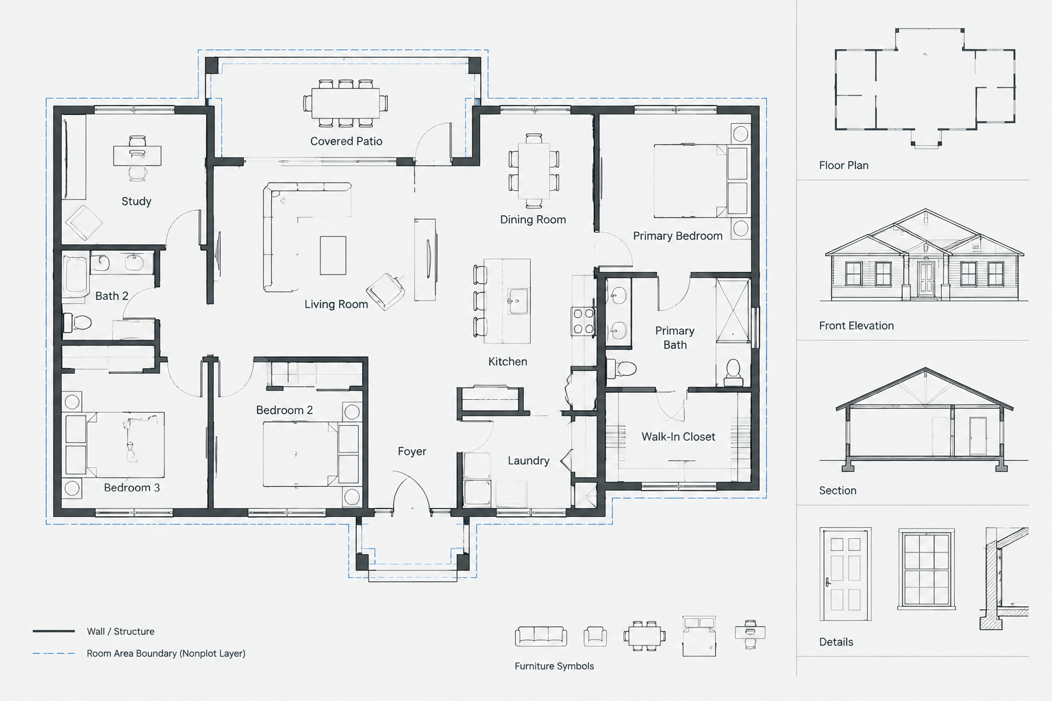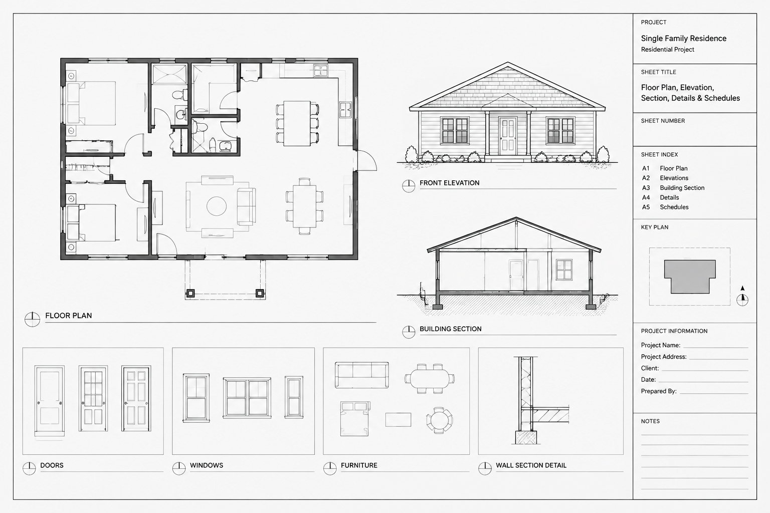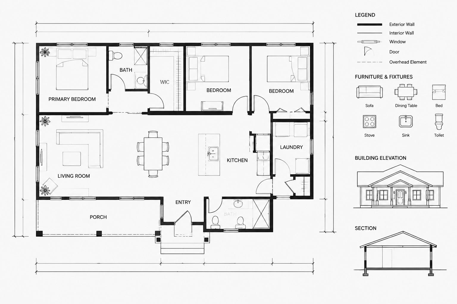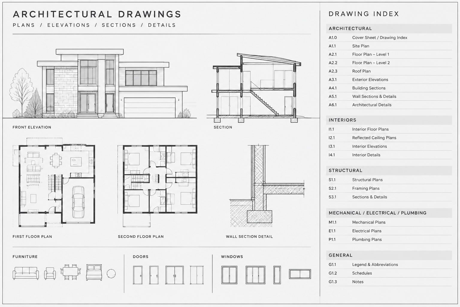
Large architectural floor plans often cannot be presented clearly on a single sheet at the intended drawing scale. Dividing the plan into several drawing areas can make each portion easier to read, but it also introduces a coordination problem: readers need to understand where one view ends, where the adjacent view continues, and how the separate sheets relate to the complete building.
Match lines provide that connection. A well-designed match-line system identifies the boundary between partial plans and directs the reader to the corresponding view or sheet. The line itself is simple; the challenging work is selecting logical split locations, maintaining overlapping information, and keeping references coordinated as the project changes.
What a Match Line Communicates
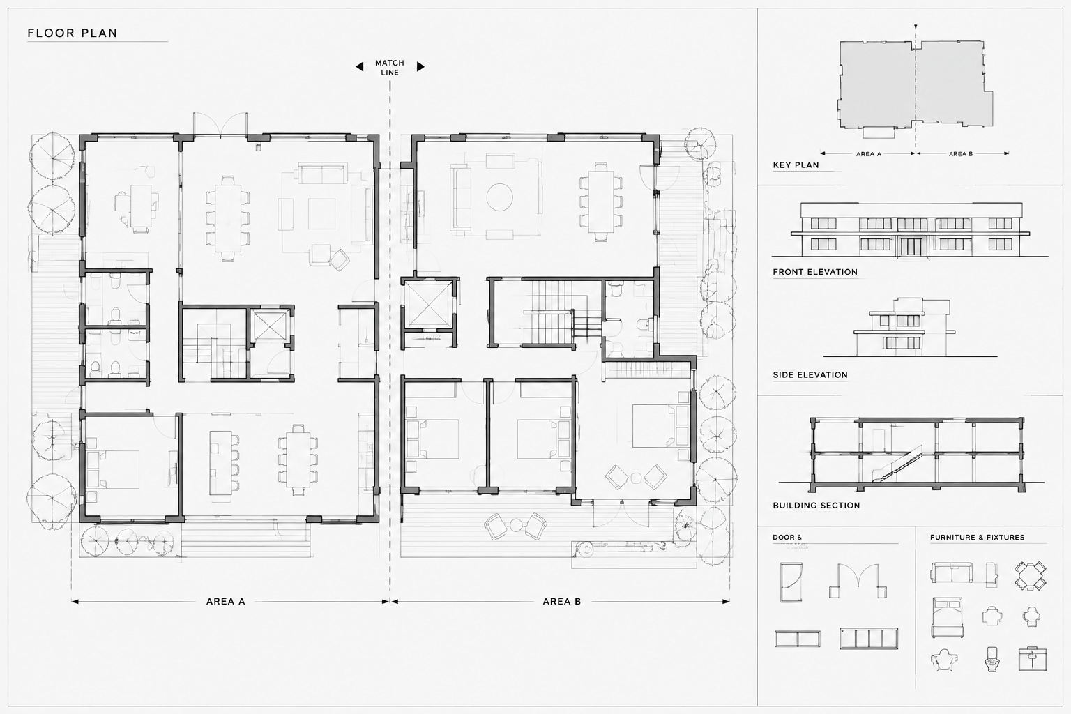
A match line marks an intentional break in a continuous plan, elevation, or other large drawing. Information on one side is shown in one view, while the continuation appears elsewhere in the drawing set. The match line typically works with a note or reference identifying the adjacent plan area.
Match lines are different from crop boundaries. A crop boundary may simply control what is visible in a viewport, while a match line is part of the drawing communication system. It tells the reader that the building or site continues and provides a path to the related view.
Match lines may be useful for:
- Large building floor plans divided into wings or zones
- Long, narrow buildings that do not fit comfortably on one sheet
- Multibuilding plans presented as coordinated partial plans
- Large roof, reflected ceiling, finish, or demolition plans
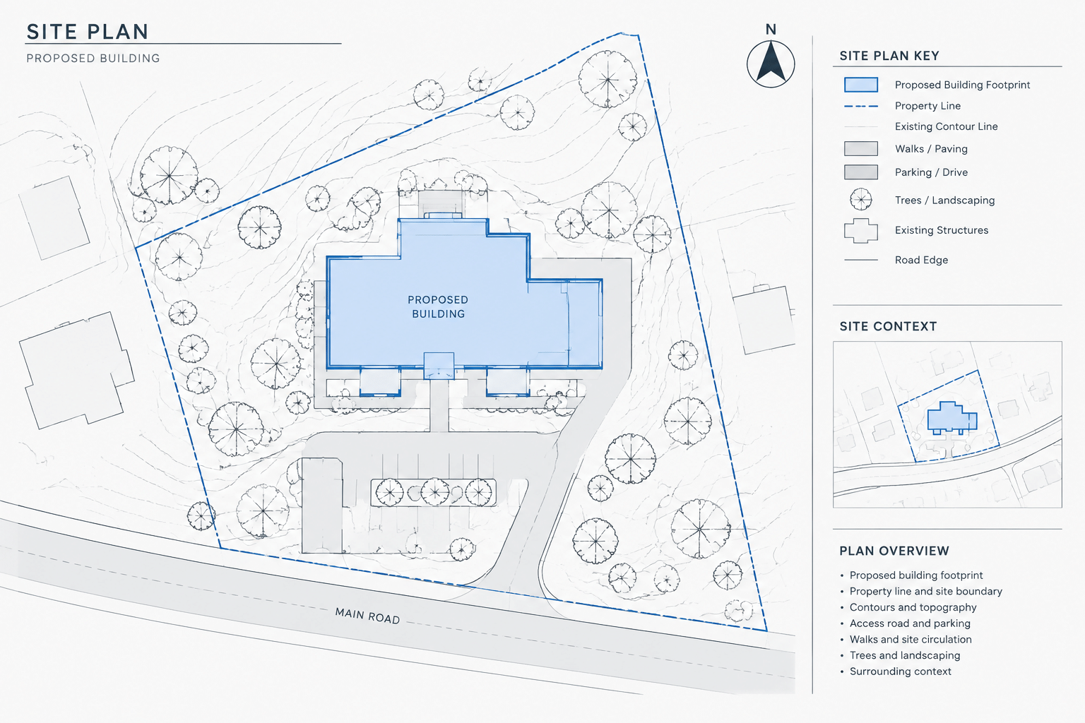
- Site plans divided into manageable drawing areas
- Elevations or linear drawings that continue across sheets
Plan the Drawing Areas Before Drafting the Lines
Do not begin by drawing an arbitrary line through the model. First decide how the building should be divided for both drafting and plan reading. The best boundary is usually one that minimizes ambiguity and avoids cutting through areas with dense coordination.
Look for logical break locations
Potential split locations include transitions between building wings, connectors, circulation zones, expansion joints, grid intervals, or relatively uncomplicated portions of the plan. These locations are often easier to recognize across architectural, structural, and building-system drawings.
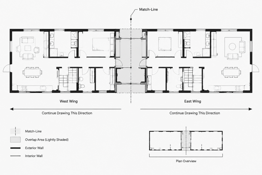
Avoid passing a match line through stairs, toilet rooms, equipment clusters, major openings, or heavily annotated intersections when another practical location is available. Splitting these areas may force the reader to move repeatedly between sheets to understand one condition.
Allow a controlled overlap
Adjacent views commonly benefit from a small overlap in visible geometry. The overlap gives the reader context and reduces the risk that walls, dimensions, or symbols appear to disappear at the boundary. Its extent should be intentional and consistent with the project’s sheet organization rather than determined by an accidental viewport crop.
Too much overlap can create another problem: the same information may appear to be documented twice. Dimensions, room tags, notes, and detail references should have a clear primary location even when geometry is visible in both views.
Test the proposed division on the sheets
Create preliminary viewports or plotted test sheets before finalizing the boundary. Confirm that each area fits at the intended scale with enough space for titles, dimensions, notes, legends, and references. A split that looks balanced in model space may create an awkward sheet when annotation is included.
A Practical CAD Workflow
1. Keep the building geometry continuous
Draft the building as coordinated geometry rather than creating unrelated copies for each sheet. If the workflow uses referenced floor-plan files, maintain a dependable project origin, rotation, and insertion relationship. The drawing areas should be different views of the same coordinated information, not separately edited versions of the building.
2. Establish named drawing areas
Assign clear area names before placing match-line notes. Names based on wings, zones, or other stable project divisions are generally easier to manage than temporary descriptions such as left side and right side. If the office uses area identifiers, apply them consistently across plan types.
A simple planning matrix can help:
| Coordination item | Question to resolve |
|---|---|
| Area identity | What stable name identifies each partial plan? |
| Primary sheet | Where is each area documented? |
| Adjacent area | Which plan continues across each boundary? |
| Overlap | What geometry remains visible in both views? |
| Annotation ownership | Which view carries dimensions, tags, and notes near the boundary? |
3. Draw match lines on a dedicated layer
Place match lines on a clearly named annotation layer rather than combining them with walls, grids, or viewport frames. A dedicated layer makes it easier to control color, linetype, lineweight, visibility, and plotting behavior according to the project’s CAD standards.
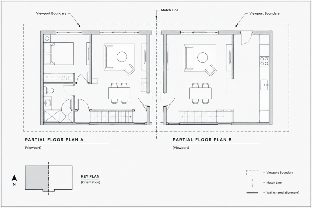
The match line should be visually distinct without overpowering the plan. Its plotted appearance needs to remain readable over hatches, existing-work graphics, furniture, and other background information. Always evaluate the result in a plot preview or test output instead of relying only on the model-space display.
4. Add directional continuation notes
Label each side of the boundary so the reader knows where the plan continues. The wording may reference an adjacent area, view, or sheet depending on the project’s documentation system. Use a consistent text style and placement convention throughout the set.
Place the note close enough to the line that its purpose is obvious, but do not cover dimensions, room information, or important geometry. If the boundary changes direction, check every segment for a clear relationship between the line and its label.
5. Coordinate viewport limits with the match line
The viewport should show enough information beyond the match line to make the transition understandable. Avoid cropping exactly at the line if doing so removes the context needed to compare the adjacent view. Conversely, do not reveal so much of the neighboring area that the documentation boundary becomes unclear.
Lock or otherwise protect finalized viewport positions according to the office workflow. An unintended pan can move the match line away from the intended sheet edge, alter the overlap, or omit geometry that appears on the adjacent plan.
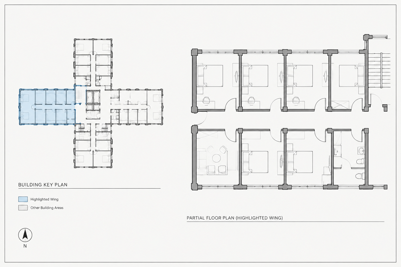
6. Place a small overall plan for orientation
A reduced overall plan can help readers understand where each partial plan is located within the building. Highlight the area shown on the current sheet and keep the graphic simple. The overall plan should support orientation rather than duplicate the detailed information in the main viewport.
Coordinate the area names used in the overall plan, viewport title, match-line notes, sheet index, and any project key plan. Conflicting area labels make navigation difficult even when each individual drawing is accurate.
Managing Annotation Near the Boundary
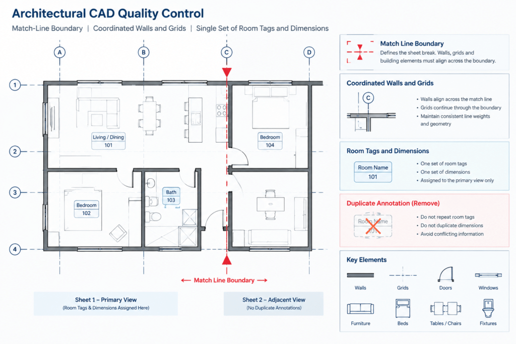
The treatment of annotation is one of the most important decisions in a split-plan workflow. Geometry may overlap, but annotation should usually have a deliberate owner.
- Dimensions: Keep complete dimension strings together when possible. Avoid dividing a continuous string between sheets unless the relationship remains unmistakable.
- Room tags: Assign each room tag to the view where the room is primarily documented. Do not let an overlap create contradictory duplicate tags.
- Door and window tags: Check openings close to the boundary and confirm that their tags remain visible in the intended view.
- Section and detail references: Place references where the cut or condition can be understood. Confirm that duplicates do not suggest separate details.
- General notes: Determine whether notes apply to one area, every partial plan, or the entire plan type. State the scope clearly.
- Revision graphics: Review both adjacent sheets when a revision occurs near a match line.
Coordinating Multiple Plan Types
Once a floor plan is divided into areas, related plan types often need to follow the same basic organization. Architectural plans, demolition plans, reflected ceiling plans, finish plans, furniture plans, and life-safety drawings may each use different graphic content, but consistent area boundaries make the set easier to navigate.
Exact boundaries do not always work for every discipline or plan type. A ceiling plan may need additional space for notes, while a site utility view may follow a different logical division. When boundaries vary, make the references explicit rather than assuming readers will infer the relationship.
Coordinate proposed area divisions with consultants before the sheet set becomes difficult to revise. Shared grid references, project coordinates, and area names can help separate drawings align even when each discipline controls its own files and sheets.
Common Match-Line Problems
- Geometry does not align: Adjacent views may use different reference positions, outdated backgrounds, or inconsistent viewport rotation.
- The line cuts through critical information: Move the boundary or adjust the sheet arrangement instead of forcing a confusing split.
- References point to old sheets: Recheck match-line notes after sheets are added, removed, or renumbered.
- Annotation is duplicated: Decide which view owns each tag, note, and dimension near the overlap.
- The adjacent view has no context: Increase the controlled overlap or improve the overall orientation graphic.
- The match line plots too strongly or disappears: Review its layer, lineweight, linetype display, and interaction with background graphics.
- Different plan types use conflicting area names: Maintain one project-wide area naming system wherever practical.
Quality-Control Checklist
Before issuing split plans, review them as connected pairs rather than checking each sheet in isolation.
- Confirm that every match line has a valid continuation reference.
- Compare geometry on both sides for alignment and current revision status.
- Verify that area names match titles, key plans, and sheet references.
- Check that the overlap provides context without creating documentation conflicts.
- Review dimensions, room tags, opening tags, and callouts near every boundary.
- Confirm that viewport scale, orientation, and visible limits are intentional.
- Inspect plotted linework to ensure the match line is clear but not dominant.
- Repeat the review after sheet-number or drawing-area changes.
Use Match Lines as a Navigation System
Effective match lines do more than divide a large plan. They form a navigation system connecting drawing areas, sheets, and related plan types. Their success depends on coordinated geometry, logical boundaries, consistent labels, controlled overlaps, and careful annotation ownership.
Plan the division early, test it in the actual sheet layout, and review adjacent views together. This approach produces split floor plans that remain understandable as the design develops and the drawing set becomes more complex.