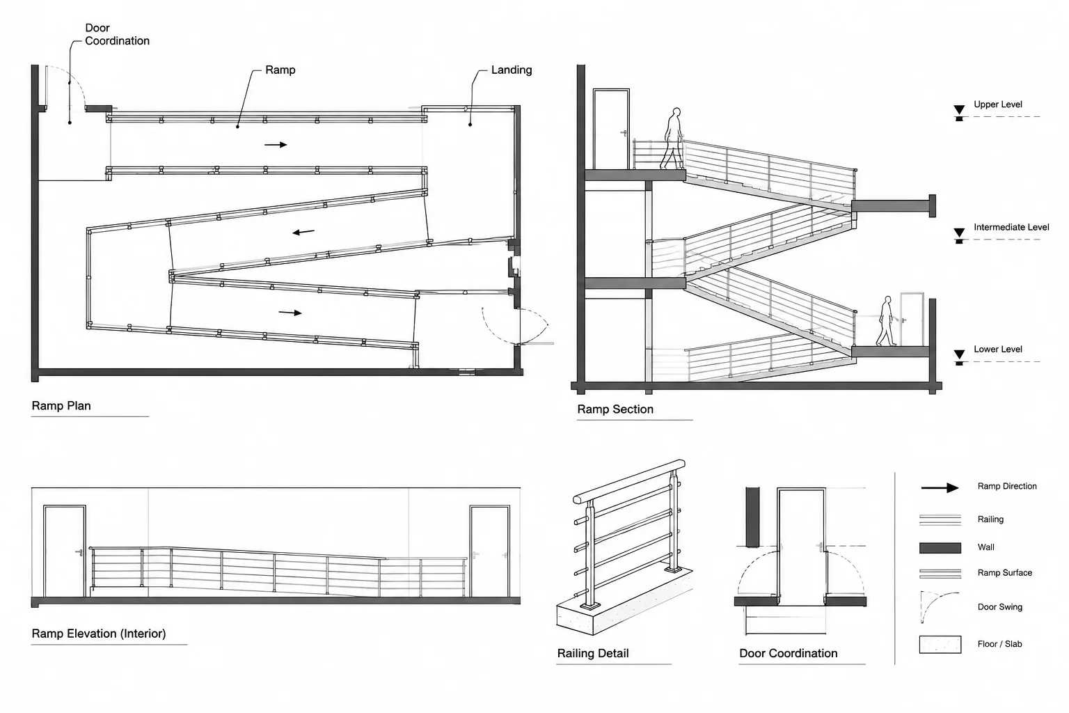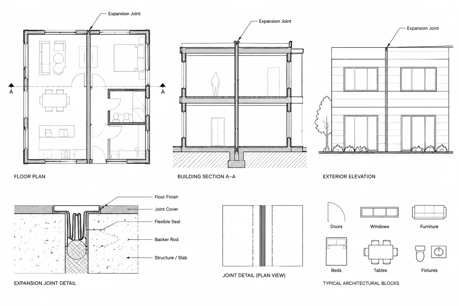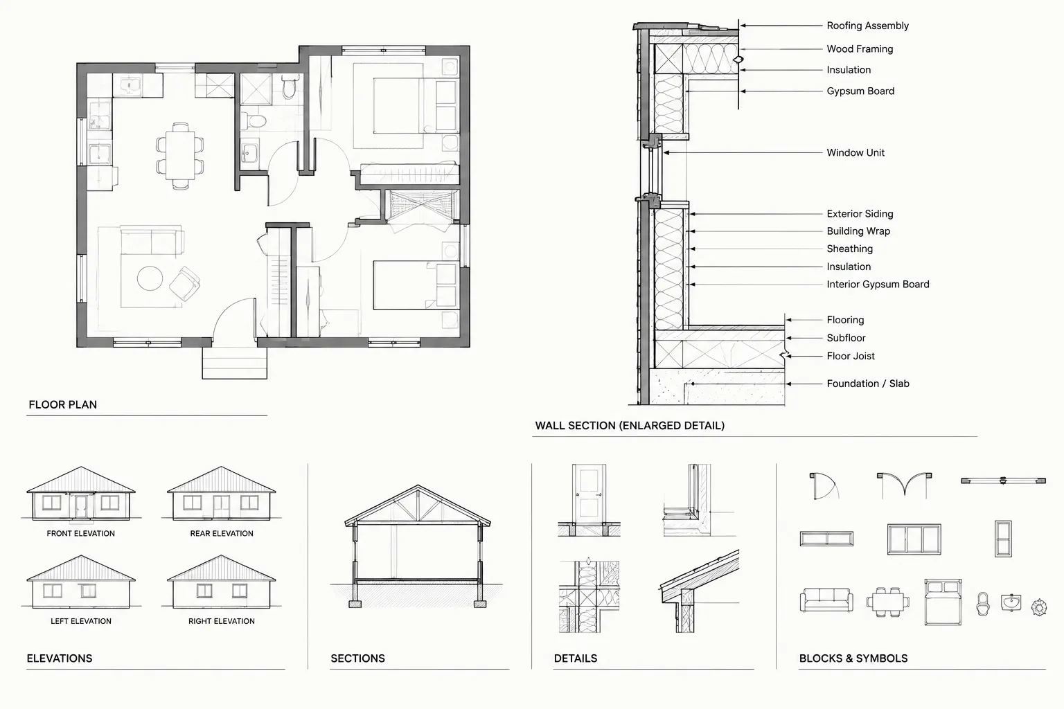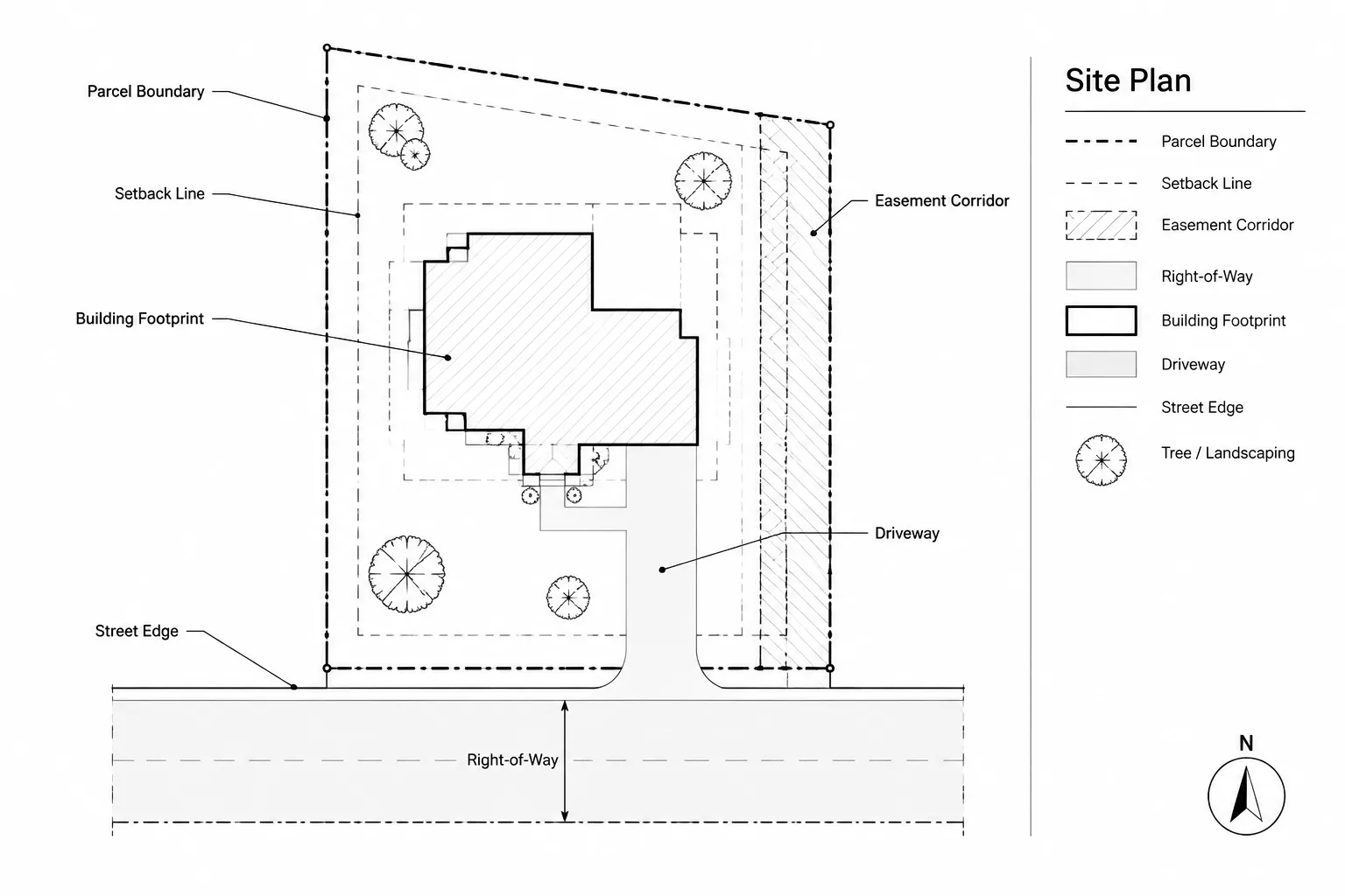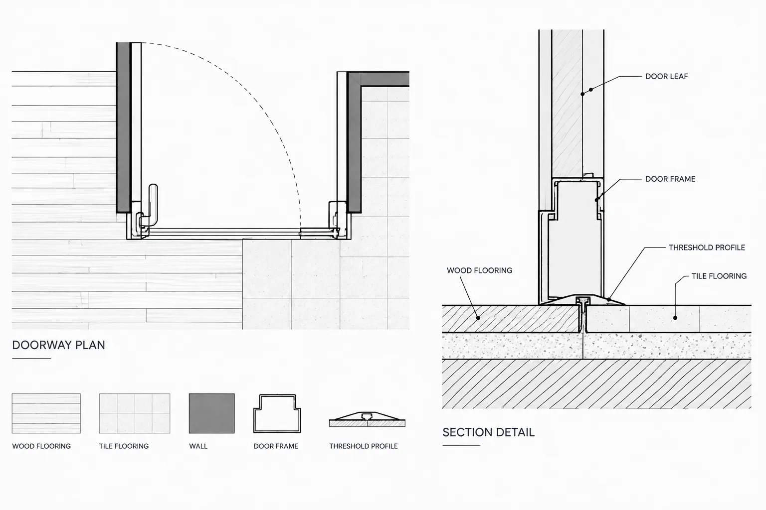
Floor transition drafting is less about drawing a dividing line and more about coordinating adjacent materials, assemblies, openings, and finish information. A clear architectural CAD detail should show where the change occurs, how the materials meet, and where the reader can find related requirements.
This guide presents a practical workflow for documenting floor transitions in plans and sections. It also explains how to coordinate threshold conditions with doors, room finishes, exterior interfaces, annotations, and reusable CAD details without implying a construction solution that has not been verified.
Floor transitions often occupy very little space in a building, but they can create significant drawing coordination problems. A finish boundary shown incorrectly in plan may conflict with a door, expose an unintended flooring edge, or disagree with the room finish schedule. A threshold detail can also become misleading when it does not account for the floor assembly, substrate, adjacent exterior surface, or door frame.
A reliable CAD workflow treats each transition as a coordinated condition rather than a decorative line between hatch patterns. The designer must determine where the finish changes, what physical component forms the transition, and which drawing view communicates the condition most clearly. The final location and construction should be verified against the project requirements, selected products, accessibility criteria, and applicable codes.
Start by Classifying the Transition
Before drawing a detail, identify the type of condition involved. Similar-looking plan graphics can represent very different assemblies.
- Finish-only transition: Two finishes meet over a common substrate, possibly with a strip, profile, joint, or other edge treatment.
- Floor-level transition: Adjacent finish assemblies create a change in finished elevation because their total thicknesses differ.
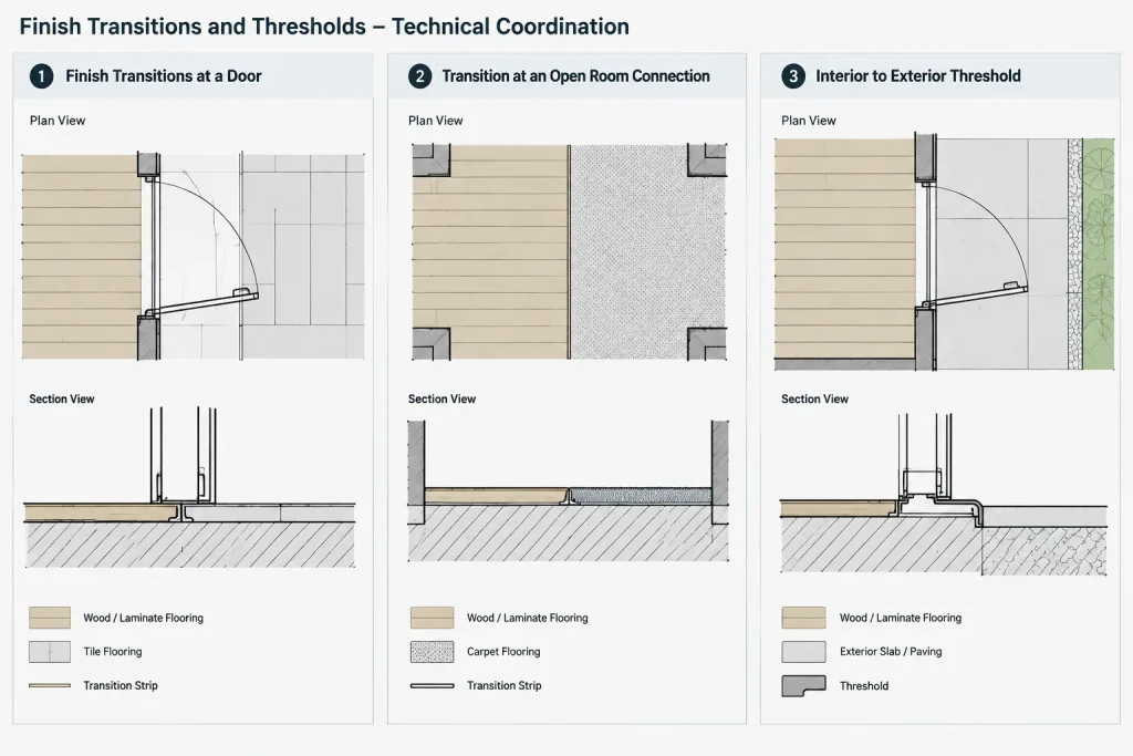
- Door threshold: The transition occurs within a door opening and may be coordinated with the frame, leaf, seals, hardware, and weather protection.
- Interior-to-exterior transition: The condition may involve drainage, waterproofing, flashing, paving, or a change in structural support.
- Movement or construction joint: The finish boundary is influenced by a joint in the supporting construction and cannot be located solely for visual convenience.
This classification helps determine whether the condition needs only a plan symbol, an enlarged plan, a section detail, or a coordinated set of views.
Place Finish Boundaries Intentionally
A floor finish boundary should not be placed merely where two hatch patterns happen to meet. Establish its location from the architectural condition that controls it.
Transitions at door openings
When different finishes meet at a door, the boundary is commonly coordinated with the door assembly so that it is visually controlled when the door is closed. The appropriate position depends on the frame configuration, door swing, leaf location, threshold type, and design intent. Do not assume that every transition belongs on the wall centerline.
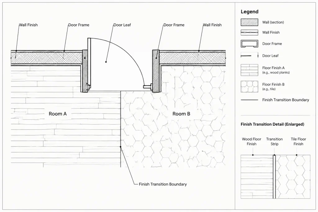
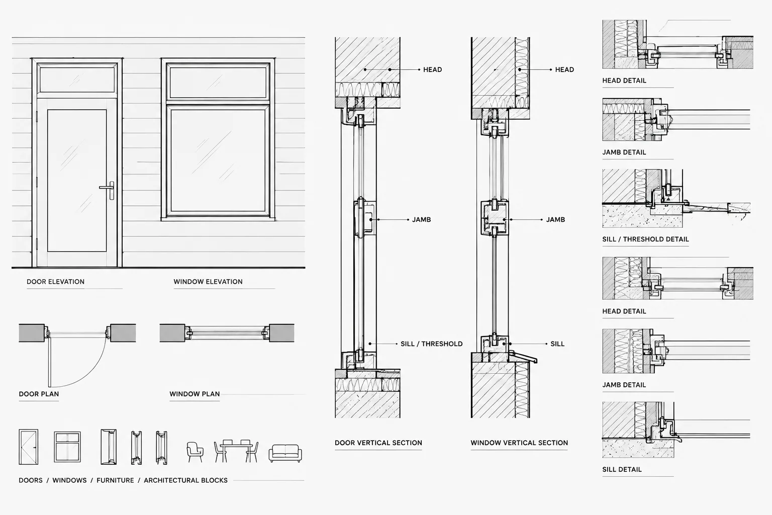
In plan, review the opening at an enlarged scale. Display the frame, door leaf, wall finishes, floor finish regions, and transition component together. This makes it easier to detect a finish line extending visibly into the wrong room or passing through frame geometry.
Transitions without doors
At an open connection between spaces, the boundary becomes a visible design element. It may align with a wall face, ceiling change, casework edge, structural grid, or another organizing feature. Confirm the intended alignment across the plan instead of allowing separate room hatches to create an arbitrary seam.
Transitions at millwork and fixtures
Clarify whether flooring continues below fixed cabinets, equipment, islands, plumbing fixtures, and built-in furniture. This affects material boundaries, finish quantities, installation sequencing, and future replacement. The plan graphics and finish notes should communicate the intended extent without relying on hatch appearance alone.
Build a Clear Plan Graphic
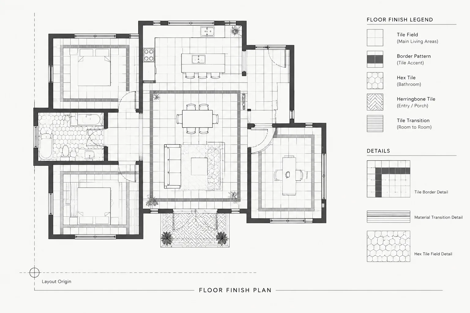
A transition plan graphic generally needs three layers of information: the finish areas, the boundary or transition element, and an identifier that connects the condition to notes or details.
- Keep finish hatches visually subordinate to walls, doors, and fixed construction.
- Draw the actual transition component at an appropriate level of detail for the view scale.
- Use a consistent line type or symbol for finish boundaries that are not physical strips.
- Avoid using a thick line that could be mistaken for a wall, curb, or structural edge.
- Use a detail callout when the plan cannot explain the vertical assembly.
- Coordinate transition identifiers with the finish legend, specifications, or material schedule.
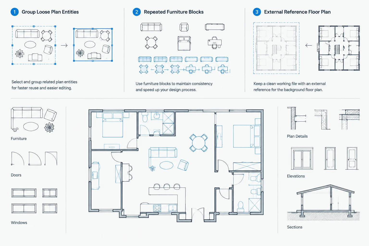
For repetitive conditions, a small CAD block with an attribute can help standardize transition tags. Keep the tag separate from the physical linework so it can be repositioned without altering the modeled location of the finish change.
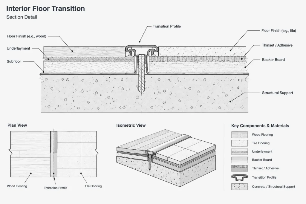
Draft the Section from the Assembly Up
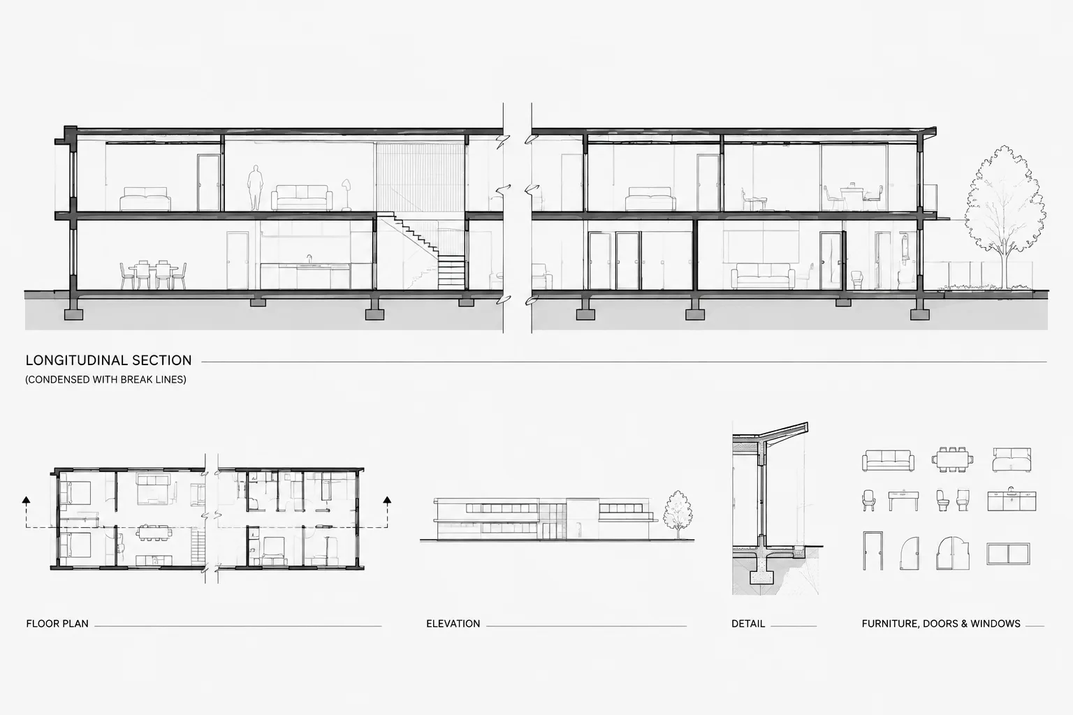
A floor transition section should explain how the adjacent assemblies meet. Begin with the supporting construction and work upward rather than drawing only the visible finish surfaces.
Show the elements needed to understand the condition, which may include the structural base, underlayment, setting material, finish layers, transition profile, threshold, sealant, membrane, and adjacent frame. The exact components depend on the project and should be confirmed with the relevant consultant, manufacturer information, and specifications.
Pay particular attention to the finished surfaces. Two materials with different assembly thicknesses may require substrate preparation or a purpose-designed transition. Avoid depicting an unexplained sloped line or filler piece simply to make the surfaces meet. If the build-up has not been resolved, mark it as a coordination issue rather than presenting an invented solution.
Use material graphics selectively
At a detail scale, poche and material hatches can distinguish layers, but too many dense patterns make a small threshold detail difficult to read. Prioritize the profile of the assembly, critical interfaces, and concise labels. Use the office hatch convention consistently and verify that patterns remain legible when plotted.
Coordinate Plans, Schedules, and Details
A correct detail can still fail if it is disconnected from the rest of the drawing set. Use a repeatable coordination sequence for every issue.
| Drawing information | Coordination question |
|---|---|
| Floor finish plan | Is the material boundary located consistently and clearly identified? |
| Door plan and schedule | Does the opening require a threshold, and is the referenced condition compatible with the door assembly? |
| Room finish schedule | Do the listed finishes agree with the graphics on both sides of the transition? |
| Enlarged plan | Is the boundary coordinated with frames, wall finishes, casework, and nearby fixtures? |
| Section detail | Are the finish elevations, supporting layers, and transition component logically resolved? |
| Exterior drawings | Are adjacent paving, drainage, waterproofing, and elevation information coordinated? |
Where a single detail is used in several locations, confirm that the underlying conditions are genuinely the same. An interior finish strip, a wet-area doorway, and an exterior threshold should not share one generic detail merely because their plan symbols look similar.
Organize Transition Details in the CAD File
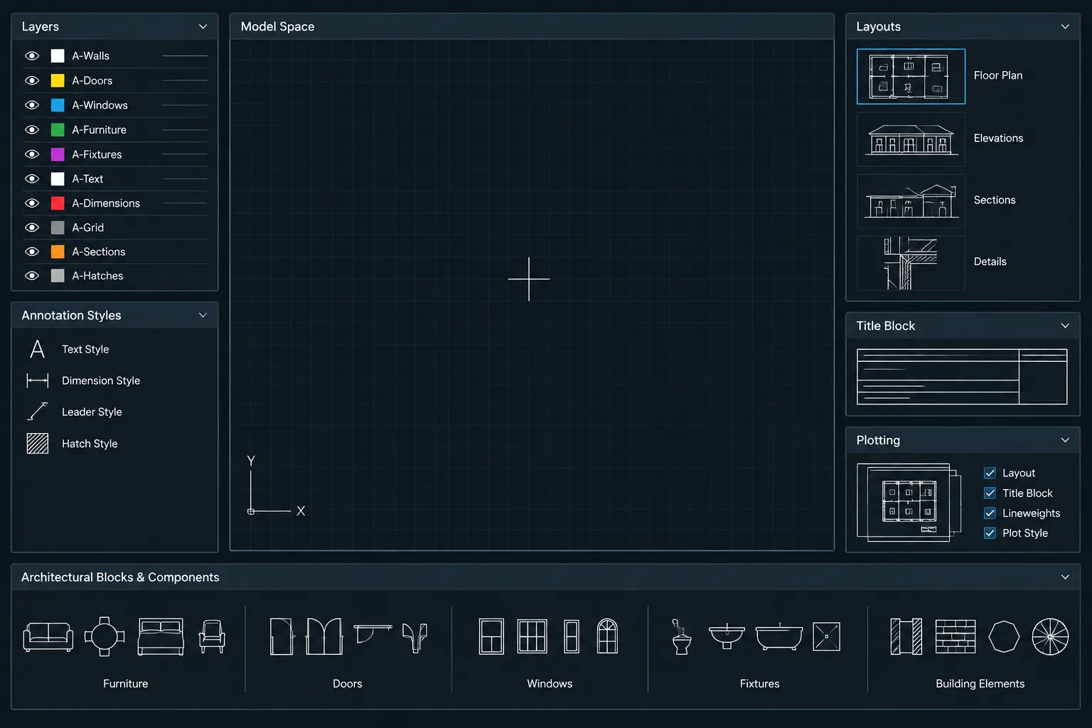
Place transition objects on layers according to their drawing function. Finish boundary lines, hatch patterns, detail components, annotation, and reference geometry should remain independently controllable. Follow the project layer standard rather than creating isolated layer names for every material.
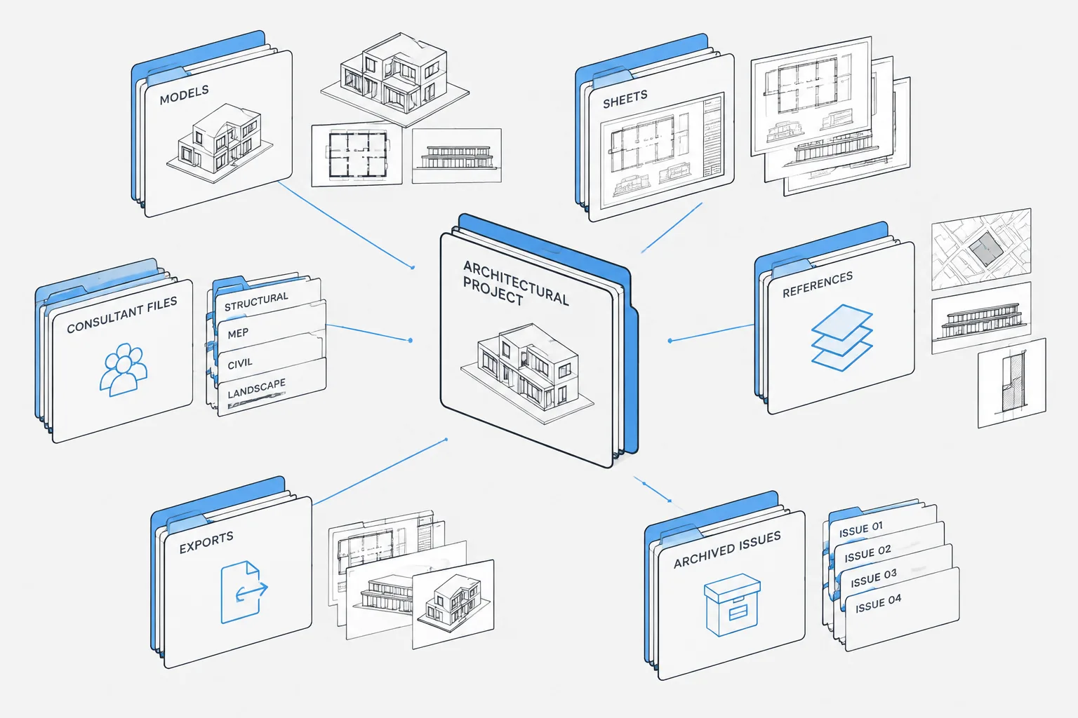
If a detail is based on an external reference, avoid tracing geometry without understanding its source. Use the referenced plan to establish the controlling opening and adjacent construction, then draw the detail in a managed detail file or designated model-space area. Record where the detail is placed on the sheets so duplicate versions do not develop.
Reusable details should contain only information that is truly typical. Project-specific products, materials, notes, and assembly assumptions should be reviewed each time the detail is inserted. A library detail is a starting point, not proof that a condition has been designed or approved.
Common Drafting Problems
- Hatches meet at the wrong location: The rooms appear correct individually, but the boundary is exposed when the door is closed.
- The plan and detail disagree: The plan shows a simple finish line while the section includes a threshold that should also be represented or tagged.
- Finish thicknesses are ignored: The section forces different assemblies into alignment without explaining the substrate or transition method.
- One symbol represents unrelated conditions: Interior, wet-area, and exterior transitions are grouped under a generic note.
- Annotations float away from geometry: Tags are copied without maintaining a clear association with the intended boundary.
- Detail content is too product-specific: A library drawing includes a profile or fixing method that has not been selected for the project.
Practical Quality-Control Checklist
- Review every finish change at doors and open connections.
- Confirm that finish boundaries align with the architectural design intent.
- Compare plan finish labels with the room finish schedule.
- Check whether differing assembly thicknesses require a resolved detail.
- Verify threshold references against door information and exterior conditions.
- Inspect enlarged plans for conflicts with frames, casework, and fixtures.
- Confirm that detail callouts point to the correct sheet and detail.
- Plot the sheet to check hatch density, line hierarchy, and tag readability.
- Flag unresolved accessibility, waterproofing, drainage, or product questions for qualified review.
A Transition Is a Small Coordination Zone
The strongest floor transition details begin with coordinated plan information. Once the location, adjoining finishes, floor build-ups, door condition, and environmental exposure are understood, the CAD detail becomes much easier to draw accurately.
Treat each transition as a small coordination zone connecting architecture, interiors, doors, finishes, and sometimes structural or waterproofing work. Clear boundaries, disciplined layer use, and deliberate references between plans and sections will produce drawings that are easier to review, revise, and construct from.
Use a Decision-Based Review Process
Before issuing a floor transition detail, review it as a connected drawing condition rather than an isolated drafting object. Begin by asking what controls the boundary: the door assembly, an alignment in the room, the floor build-up, a construction joint, or an exterior interface. That answer should guide the location of the plan line and the content of the section.
Next, separate confirmed information from unresolved information. Confirmed materials and components can be drawn and labeled directly. Unknown profiles, substrate adjustments, membranes, or attachment methods should be identified for coordination rather than represented with assumed geometry.
Check the condition from both sides
A transition may appear correct when viewed from one room but create an exposed edge or conflicting note in the adjoining space. Review the plan from both sides of the boundary, including the closed-door condition where applicable. Compare the result with the finish schedule, door information, enlarged plans, and any related exterior drawing.
Preserve editability in CAD
Keep finish regions, physical transition components, reference geometry, and annotation independently editable. This allows the material boundary to be revised without unintentionally moving a tag or changing the door geometry. It also makes plotting and quality-control reviews easier because graphic categories can be isolated and inspected.
Record project-specific decisions
When a typical detail is adapted, identify which parts remain generic and which parts depend on the project. Material selections, threshold profiles, environmental exposure, and adjacent assemblies can change the meaning of otherwise similar linework. Recording those decisions helps prevent an outdated library condition from being reused elsewhere without review.
What a Reviewer Should Be Able to Understand
- Which materials or assemblies meet at the transition.
- What establishes the location of the finish boundary.
- Whether a physical strip, threshold, joint, or profile is present.
- How the condition relates to the door frame or open connection.
- Whether the adjacent finished surfaces align or change elevation.
- Which notes, schedules, or details contain the supporting information.
- Which product, accessibility, drainage, or waterproofing questions remain unresolved.
If these points cannot be understood without guessing, the condition needs clearer geometry, annotation, references, or coordination before issue.
Frequently Asked Questions
Should every floor finish change have a section detail?
Not necessarily. A plan boundary and clear identifier may be sufficient for a straightforward finish change over a common supporting assembly. A section becomes more important when the condition involves different build-ups, a threshold, a level change, a door assembly, exterior exposure, waterproofing, drainage, or another interface that cannot be explained in plan.
Where should a floor transition be placed at a door?
The location should be coordinated with the frame, leaf position, swing, wall finishes, threshold type, and intended appearance when the door is closed. The wall centerline should not be used automatically unless it is confirmed as the controlling alignment.
Should a threshold be drawn as part of the door or the floor finish plan?
It may need to appear in both drawing systems, depending on the condition and documentation method. The important requirement is that the door information, finish plan, schedule, and detail describe the same coordinated assembly without contradictory symbols or notes.
How should an unresolved floor build-up be shown?
Do not draw an assumed filler, slope, or attachment method as if it were approved. Show the known adjacent assemblies, identify the unresolved interface, and flag it for coordination with the appropriate project team member, product information, and specifications.
Can one typical threshold detail be used throughout a project?
Only when the relevant conditions are genuinely equivalent. Interior finish changes, wet-area openings, exterior doors, and movement joints can require different components and coordination. Each location should be checked before assigning a typical detail.
How can finish hatches remain readable around transitions?
Keep hatch graphics subordinate to walls, frames, transition components, and annotation. Review the plotted output rather than relying only on the on-screen display, and avoid dense patterns that obscure the boundary or nearby door geometry.