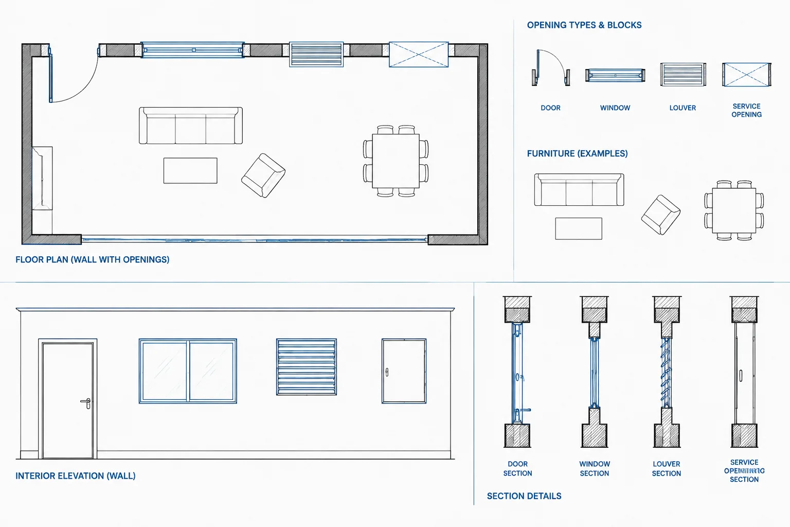
Drafting wall openings in architectural CAD requires more than trimming wall lines around a door, window, louver, panel, or service penetration. Each opening must remain consistent with its host wall, installed assembly, controlling dimensions, annotations, schedules, details, and consultant information.
The following workflow explains how to organize opening geometry, distinguish construction and finished conditions, coordinate related drawing views, and review revisions without allowing duplicated information to drift out of alignment.
Wall openings are easy to draw as gaps between lines, but they are not simple coordination items. Each opening may affect architectural finishes, structural framing, exterior weather protection, fire-resistance requirements, building services, and installation tolerances. If the opening is represented differently in plans, elevations, sections, and schedules, the drawing set can quickly become unreliable.
A dependable workflow treats wall openings as coordinated project elements rather than isolated pieces of geometry. The objective is to establish what creates the opening, which dimensions control it, and where related information belongs in the drawing set. This guide applies to door and window openings, louvers, access openings, pass-throughs, recessed assemblies, and larger service penetrations. Project-specific dimensions and requirements must still be verified with the appropriate consultants, manufacturers, and governing criteria.
Begin by Classifying the Opening
Not every interruption in a wall should be documented in the same way. Before drafting, classify the opening according to its function and the element installed within it.
- Door opening: Coordinated with a door, frame, hardware information, wall type, and door schedule.
- Window opening: Coordinated with the window unit, sill and head conditions, exterior elevation, and window schedule.
- Louver or vent opening: Coordinated with mechanical requirements, exterior appearance, frame conditions, and weather protection.
- Access opening: Coordinated with an access panel, removable cover, equipment clearance, or maintenance route.
- Service penetration: Created for ducts, pipes, conduits, cable systems, or other building services.
- Architectural pass-through: An intentionally open connection that may require finished jambs, a sill, trim, or protective edges.
- Recess or niche: A partial-depth condition rather than a complete penetration through the wall.
This classification determines whether the item needs a type mark, schedule entry, detail reference, consultant tag, or only a coordinated outline. Avoid forcing unlike conditions into one generic opening symbol.
Distinguish the Different Opening Dimensions
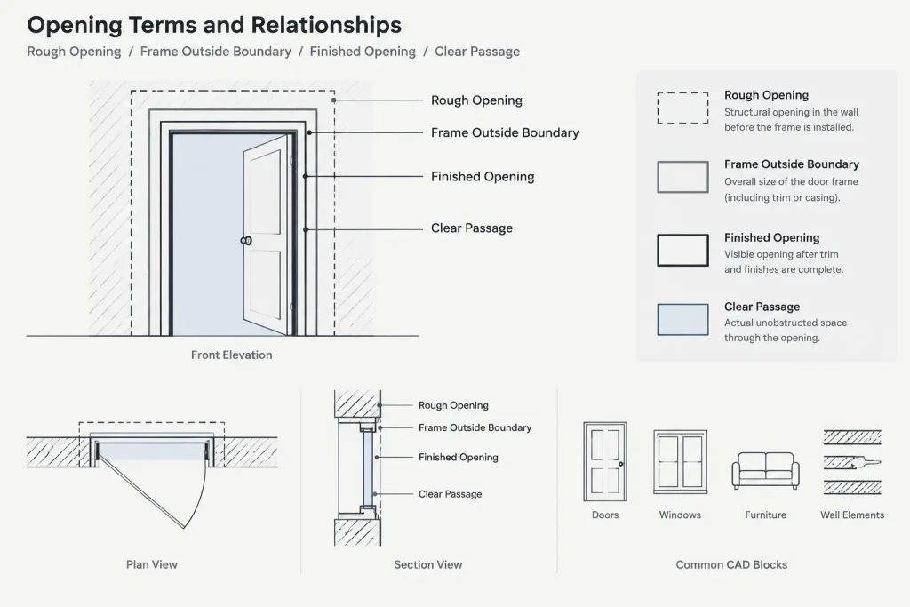
The word opening can refer to several different measurements. A designer may be describing the visible finished opening, while a fabricator may need the framed or masonry opening. The distinction should be explicit.
| Dimension concept | What it describes | Coordination concern |
|---|---|---|
| Nominal unit size | The designated size or type of the installed component | May not equal the surrounding construction opening |
| Rough or construction opening | The opening prepared in framing, masonry, or another substrate | Must account for the selected assembly and installation method |
| Frame outside size | The overall extent of a door, window, louver, or access frame | Must fit the verified construction opening |
| Finished opening | The visible opening after finishes, trim, or liners are installed | Can differ from the rough opening on every side |
| Clear opening | The unobstructed usable space through an installed assembly | May be affected by leaves, stops, hardware, tracks, or projections |
Do not assume that one dimension can represent all five concepts. Decide which dimensions the architectural drawings control and label them accordingly. When a required opening depends on a selected product, identify the need for product verification instead of deriving an unsupported value.
Establish a Stable CAD Representation
Use wall geometry as the primary reference
Locate an opening from stable building control geometry such as column grids, structural faces, established wall faces, or fixed room boundaries. Chained dimensions from one opening to the next can accumulate errors and make revisions difficult to interpret.
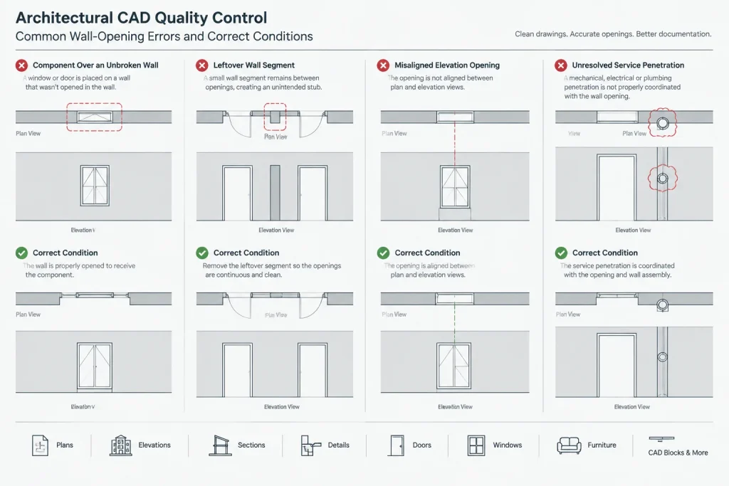
The wall and opening geometry should meet cleanly. Trimmed wall lines, poche boundaries, insulation graphics, and finish lines should not continue through an opening unless they represent a real overhead, concealed, or sectional condition. At intersections, inspect the drawing at close range to find short residual segments and unintended gaps.
Separate host geometry from inserted components
A useful CAD structure distinguishes the wall opening from the item placed in it. The wall may be part of an architectural background or wall assembly, while the door, window, louver, or panel may be a block or separately managed object.
This separation allows a drafter to answer two different questions: where is the construction opening, and what component occupies it? It also makes it easier to test alternative products without losing the original wall location.
Apply layers by information purpose
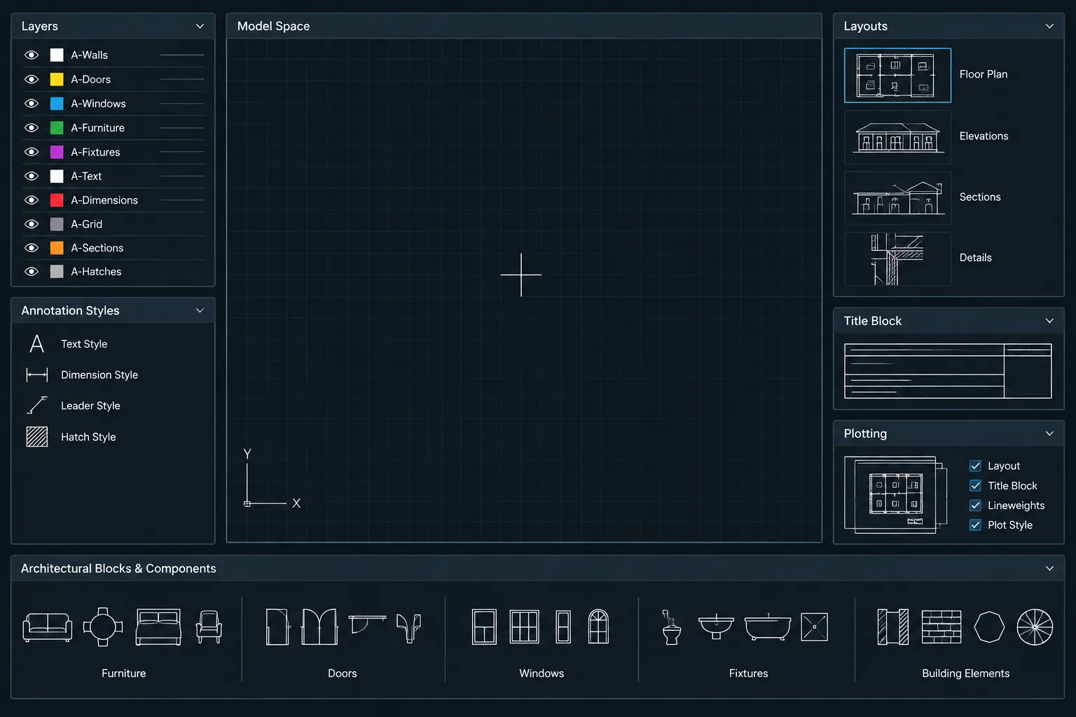
Use the project layer system rather than creating an opening layer for every possible condition. Relevant information may include wall outlines, component graphics, overhead lines, hidden edges, tags, dimensions, clearance zones, and revision annotations. Objects should generally inherit their display properties from the intended layer unless a controlled exception is necessary.
Consultant openings should remain visually distinguishable during coordination. Do not copy service penetrations into the architectural model and then allow the copies to drift away from the consultant background.
Coordinate Plans, Elevations, and Sections
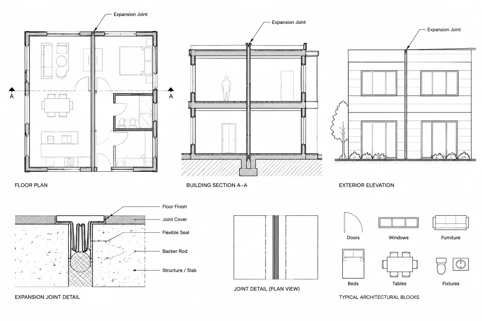
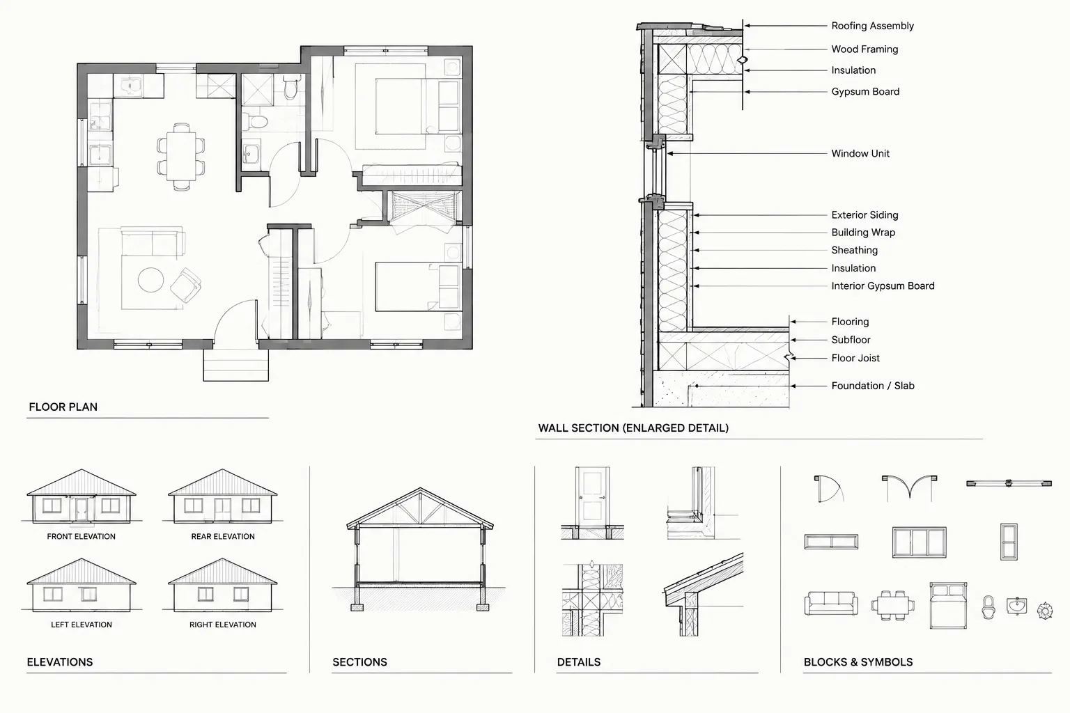
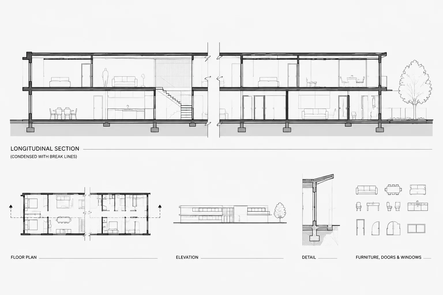
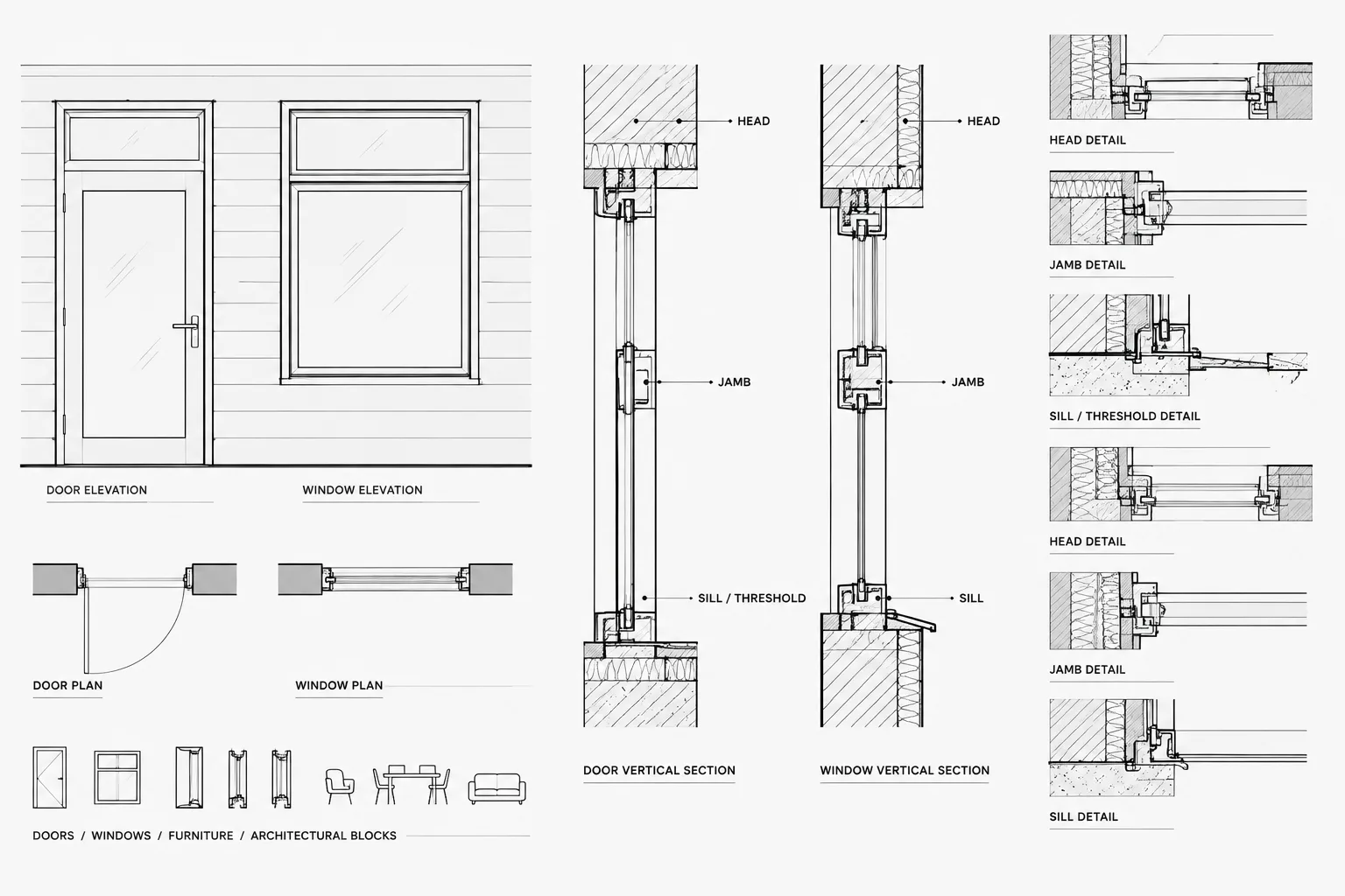
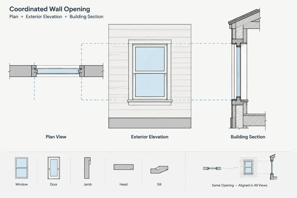
A plan identifies the opening’s horizontal position and relationship to the wall. An elevation shows width, height, alignment, and composition. A section or detail explains depth, support, finish returns, and transitions. These views should describe the same condition from different directions.
Plan checks
- Confirm the correct wall receives the opening.
- Check the opening against wall intersections, columns, pilasters, casework, and equipment.
- Verify door swings and adjacent circulation without treating the swing arc as the clear opening.
- Show overhead portions with the project’s established line convention.
- Review whether finishes wrap into the jamb or stop at a frame.
- Confirm tags remain associated with the correct components after revisions.
Elevation checks
- Align heads and sills intentionally rather than relying on visual approximation.
- Coordinate openings with ceiling lines, soffits, exterior bands, joints, and adjacent trim.
- Compare repeated opening types for inconsistent proportions or accidental mirroring.
- Show major louvers and service openings where they affect the architectural composition.
Section and detail checks
- Identify the supporting construction at the head and sill where relevant.
- Coordinate wall depth, frame depth, finish returns, and sealant or closure zones conceptually.
- Trace enclosure control layers around exterior openings rather than ending them without explanation.
- Confirm that an opening does not conflict with beams, slab edges, bracing, or other structural elements.
Manage Repeated and Typical Openings Carefully
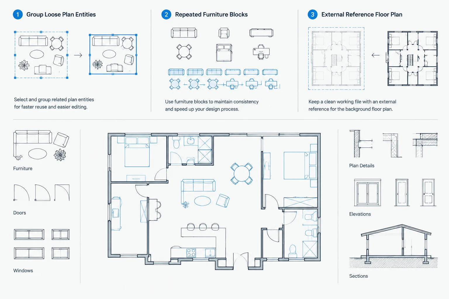
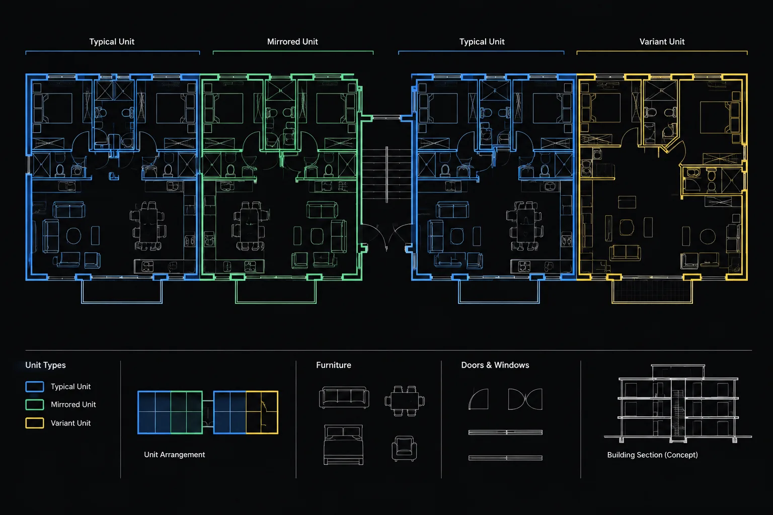
Blocks are useful for repeated openings, but repetition should not hide meaningful differences. A single block may be appropriate when geometry and annotation behavior are genuinely consistent. Separate definitions may be safer when frame depth, sill condition, wall construction, operation, or detailing changes.
Use a clear insertion point tied to a known control location, such as the opening centerline or a designated frame corner. Document that convention within the office library so users do not place identical blocks by different references. Test blocks when mirrored or rotated, especially when they contain text, directional symbols, asymmetric frames, or door swings.
A block attribute can carry an identifier, but it should not become an isolated substitute for the schedule. Type marks, instance numbers, and schedule records need a deliberate relationship that can be checked visually and systematically.
Coordinate Structural and Building-Service Openings
Architectural drawings often show openings requested by structural, mechanical, electrical, plumbing, or specialty systems. Their inclusion in an architectural file does not establish technical approval. The responsible discipline must verify size, elevation, location, support, and any required treatment.
For coordination, maintain an opening register or review list for significant non-door and non-window penetrations. Useful fields can include:
- Unique opening identifier
- Responsible discipline
- Host wall and drawing location
- Opening purpose
- Width, height, and elevation as provided or verified
- Status, such as proposed, reviewed, revised, or removed
- Related detail or consultant reference
Differentiate a proposed opening from a confirmed opening in the working process. Remove temporary status graphics before issue unless they form part of the project’s established documentation method.
Dimension and Annotate Without Creating Conflicts
Dimension openings from the control points needed for construction and coordination. Depending on the condition, that may be a centerline, jamb, frame edge, or rough opening edge. Avoid mixing these references in one dimension string without clear notation.
Vertical information can be communicated through elevations, sill or head annotations, schedules, sections, or a combination of these. Select one authoritative location for each type of information. Repeating the same dimension on many views increases the chance that one copy will remain unchanged after a revision.
Generic notes such as verify opening are not a substitute for defining responsibility. A useful note indicates what must be verified and against which source, such as a selected assembly, consultant requirement, or field condition.
Use a Focused Quality-Control Pass
Opening coordination is easier when reviewed as its own drawing-set task. Isolate relevant layers, compare plans with elevations, and inspect schedules alongside enlarged views and details.
- Search for wall gaps without components or tags.
- Search for components placed over unbroken wall geometry.
- Compare opening identifiers against schedules and type elevations.
- Check that removed openings are gone from every affected view.
- Review mirrored blocks for reversed text or incorrect operation.
- Confirm that xref updates did not shift consultant penetrations.
- Check head and sill alignments across related elevations.
- Inspect exterior openings for unresolved enclosure transitions.
- Plot a test sheet to verify lineweights, hidden lines, masks, and tag readability.
A Practical Opening Workflow
- Classify the opening and identify the responsible discipline.
- Establish the host wall and stable location references.
- Define which opening dimension is being shown.
- Create or insert the associated component using approved project content.
- Coordinate the opening in plan, elevation, and section as needed.
- Add identifiers, dimensions, and references at their designated information sources.
- Compare architectural geometry with structural and service backgrounds.
- Update schedules and opening review records.
- Run a dedicated quality-control and plotted-sheet check.
A well-coordinated wall opening is more than a clean gap in two wall lines. It is a consistent relationship among the host construction, installed component, controlling dimensions, related views, and responsible disciplines. Building that relationship into the CAD workflow reduces ambiguous dimensions, mismatched elevations, and late discoveries at walls that multiple systems need to use.
Resolve Opening Discrepancies Before Issue
When plans, elevations, sections, schedules, or consultant backgrounds disagree, avoid correcting only the view where the conflict was discovered. First identify the authoritative source for the affected information. The controlling source may differ for location, assembly type, vertical placement, structural support, or service requirements.
Trace the discrepancy back to the host wall and opening identifier, then review every dependent representation. A corrected plan opening may also require changes to an elevation, section marker, component block, schedule record, detail reference, or consultant coordination note. Record unresolved items clearly rather than concealing them with graphical adjustments.
Prepare Opening Information for Handoff
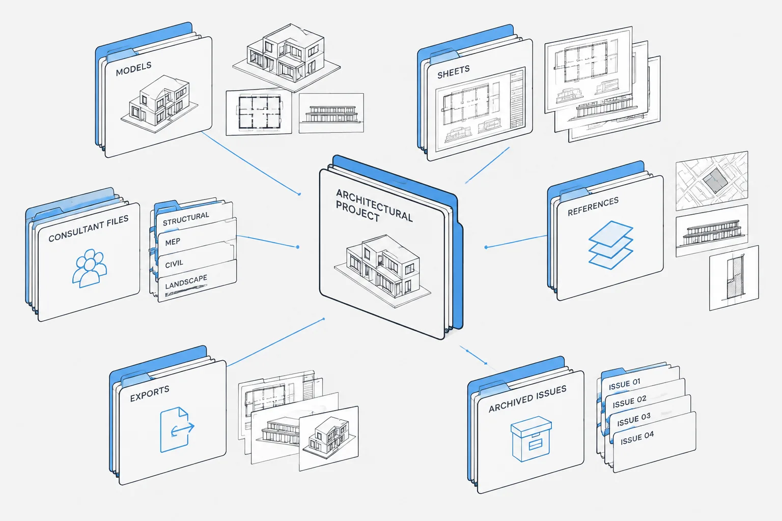
Before another drafter, consultant, or project team member uses the file, make the opening logic understandable without relying on personal knowledge. Opening identifiers should be legible, component blocks should use the office insertion convention, and temporary coordination graphics should be distinguishable from issue-ready documentation.
- Confirm that opening geometry is assigned to the intended project layers.
- Identify which view or schedule controls each repeated piece of information.
- Retain meaningful references to consultant requests and related details.
- Remove abandoned geometry, duplicate tags, and superseded coordination marks.
- Communicate unresolved product, field, structural, or service questions.
This handoff review helps preserve the relationship between the opening and its supporting information when files are exchanged, backgrounds are updated, or drawing responsibilities change.
Frequently Asked Questions
Should a wall opening and its inserted component be drawn as one object?
Not necessarily. Separating the host-wall opening from the door, window, louver, access panel, or other component makes it easier to coordinate construction geometry and test component changes independently. The project CAD standard should determine how that separation is managed.
What is the difference between a rough opening and a clear opening?
A rough or construction opening is prepared in the wall substrate for an assembly. A clear opening is the unobstructed usable space remaining through the installed assembly. Frames, leaves, stops, tracks, hardware, finishes, and projections can make these conditions different.
Should openings be located by centerline or by an edge?
Use the control point appropriate to the project and construction condition. A centerline, jamb, frame edge, or rough-opening edge may be suitable, but the reference must be identified clearly and used consistently. Avoid mixing control points in the same dimension string without explanation.
How should consultant-requested penetrations appear in an architectural file?
They should remain traceable to the responsible discipline and visually distinguishable during coordination. Their appearance in an architectural file does not establish approval of their location, size, support, or required treatment.
Why can a block look correct in plan but still cause coordination problems?
A block may fit the plan while using the wrong insertion point, identifier, wall depth, orientation, or elevation relationship. Mirroring can also reverse text, operation, or asymmetric geometry. Review repeated content in every relevant view and against its schedule information.
What should be checked after an opening is moved?
Review the host wall, dimensions, tags, elevations, sections, details, schedules, structural relationships, service backgrounds, finishes, and adjacent components. Also confirm that obsolete geometry and annotations have been removed from every affected view.