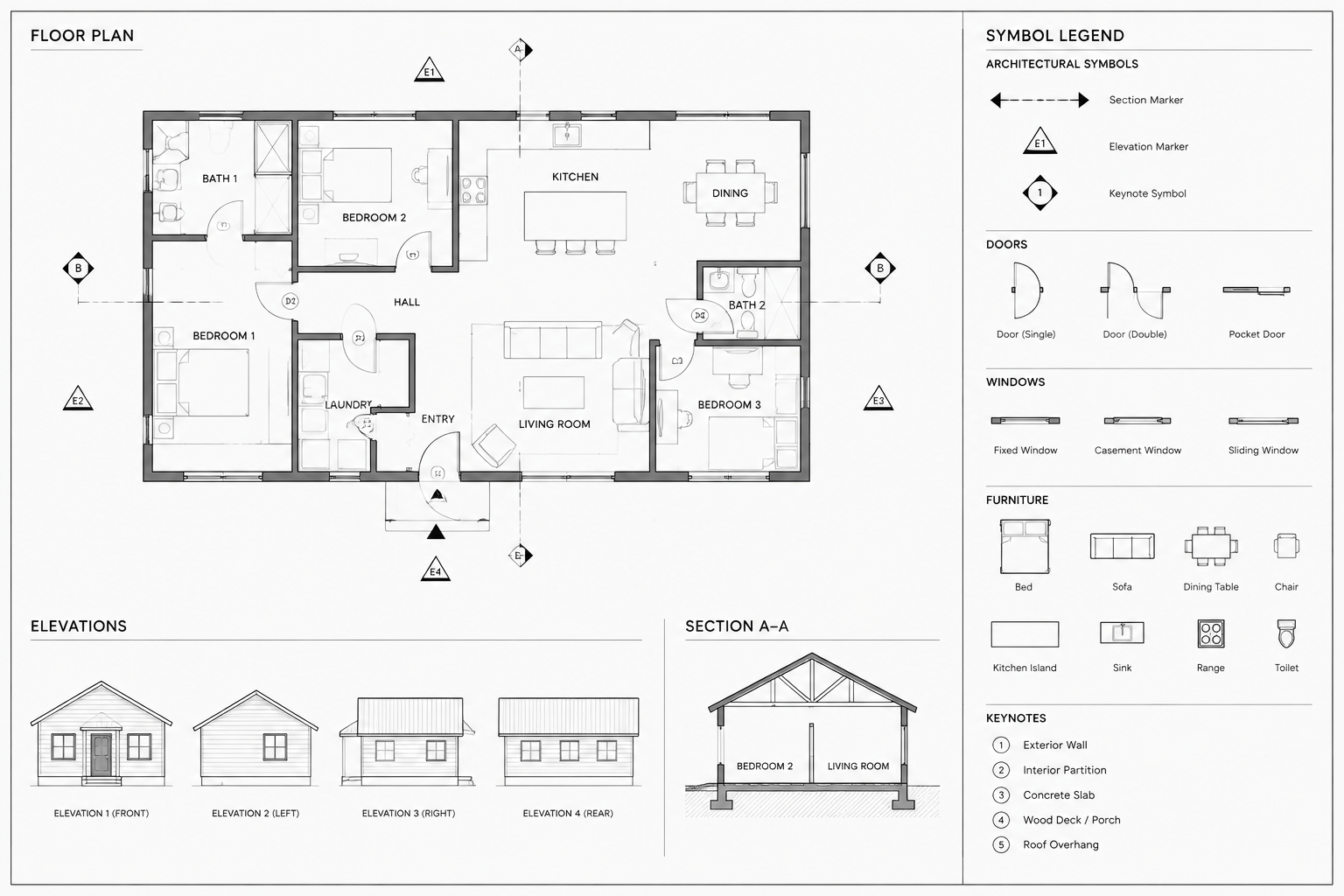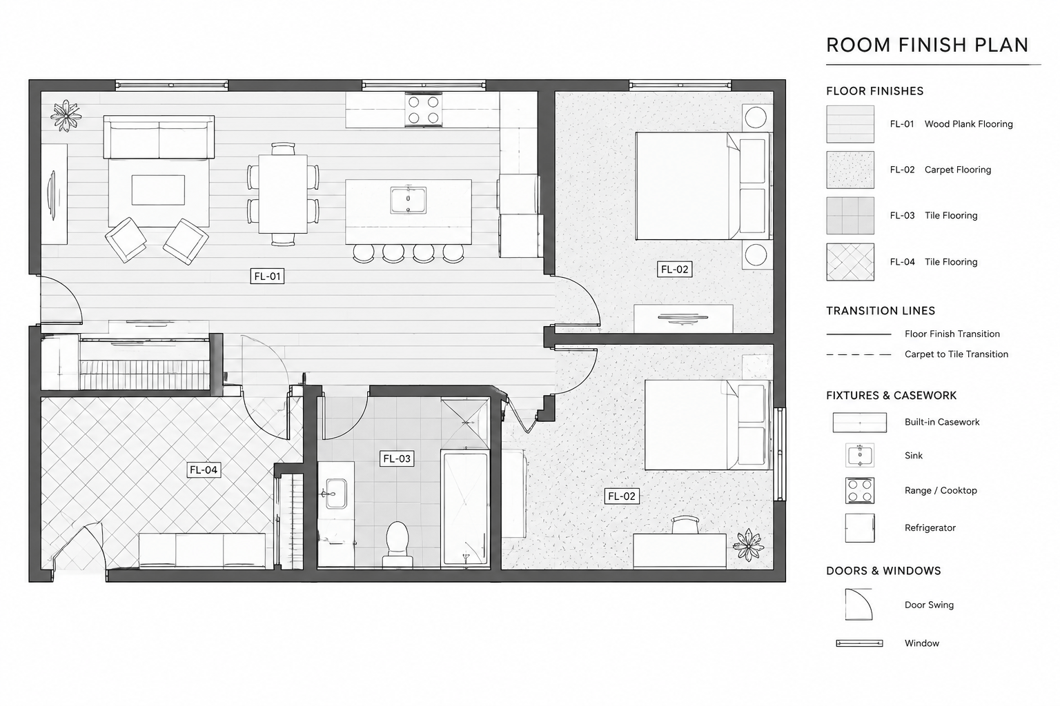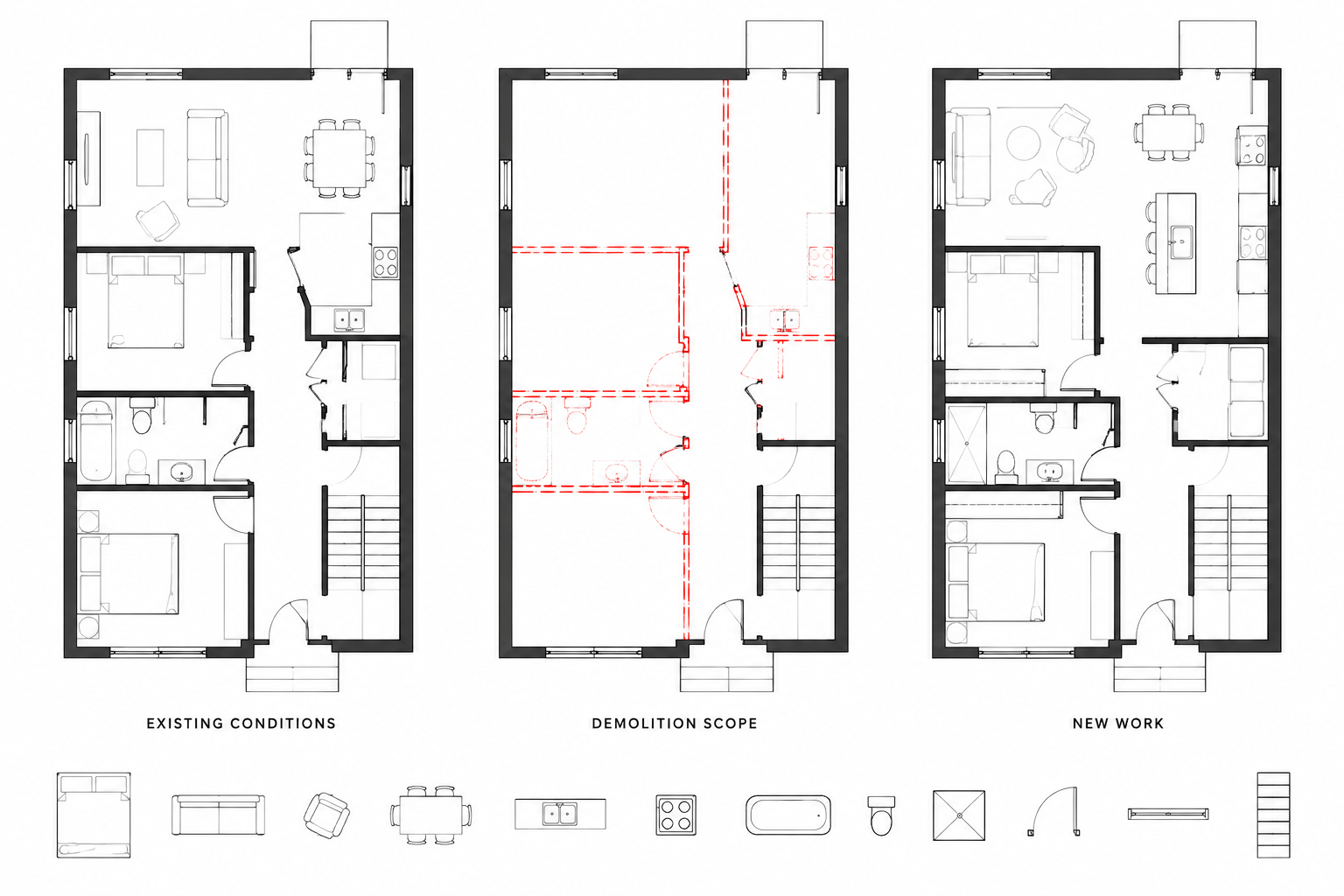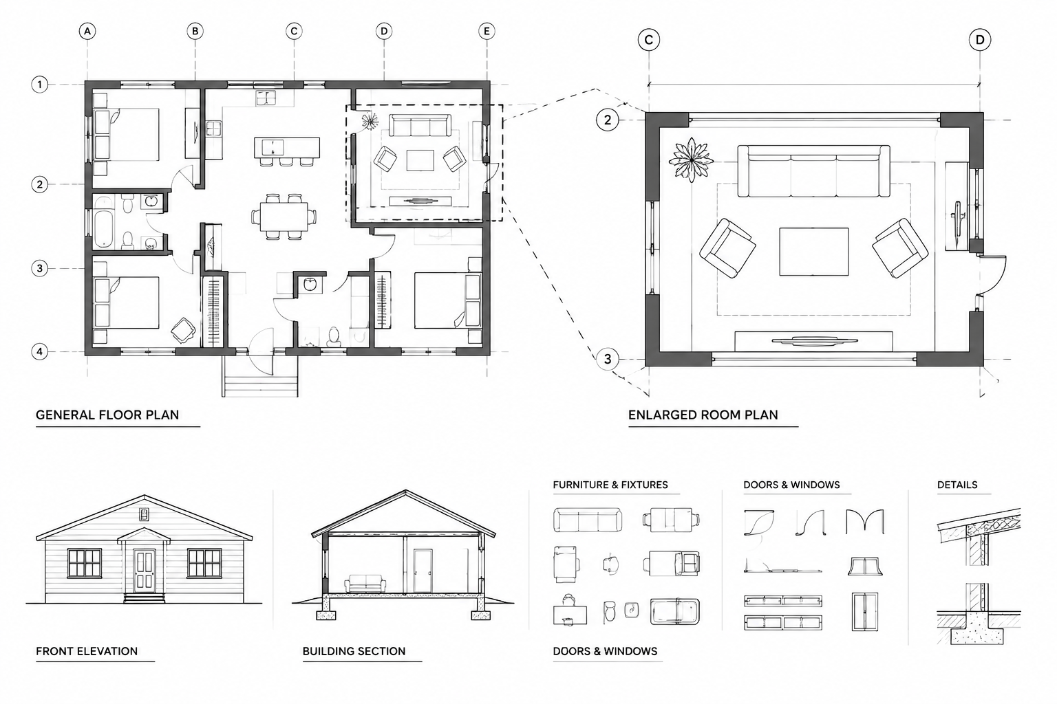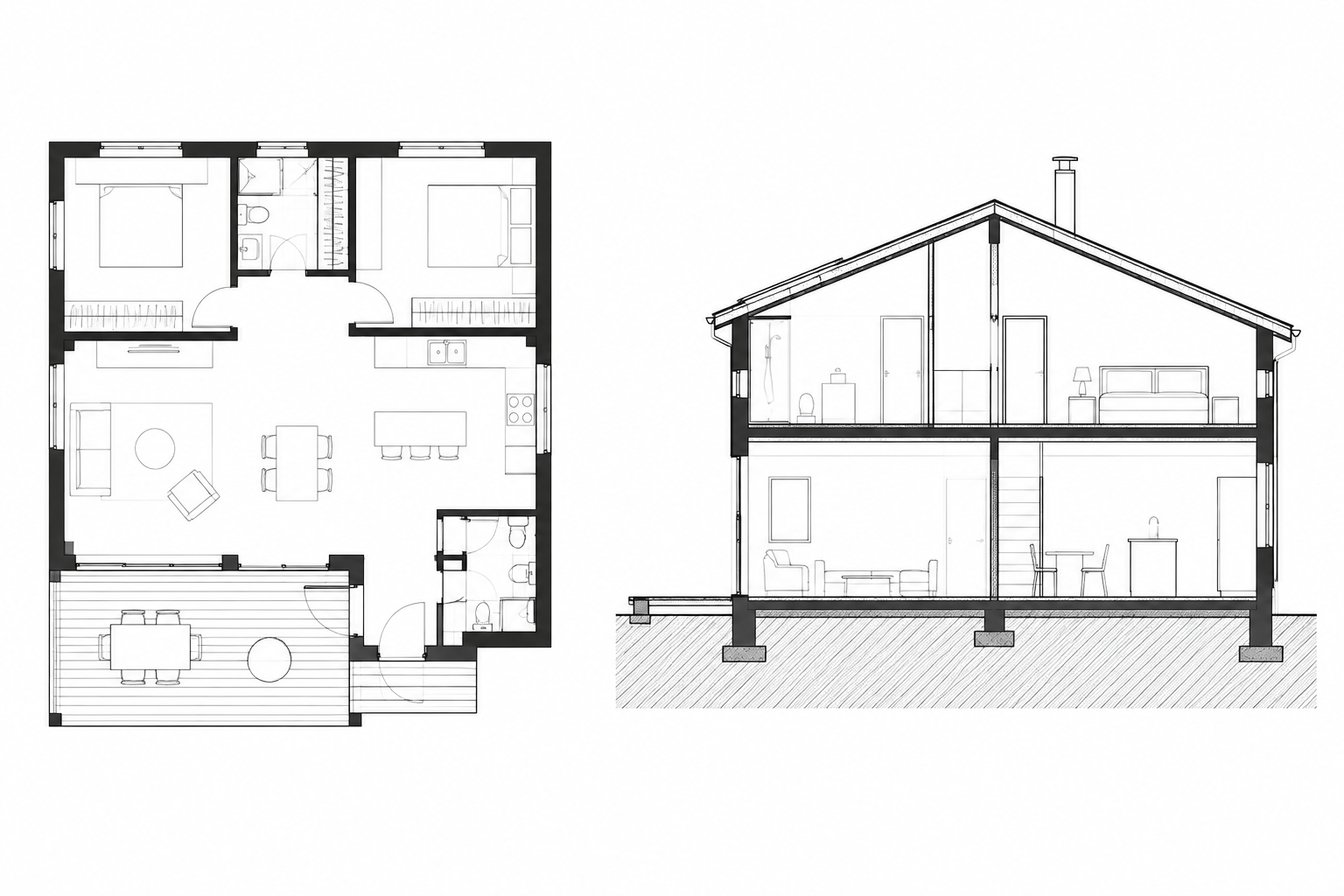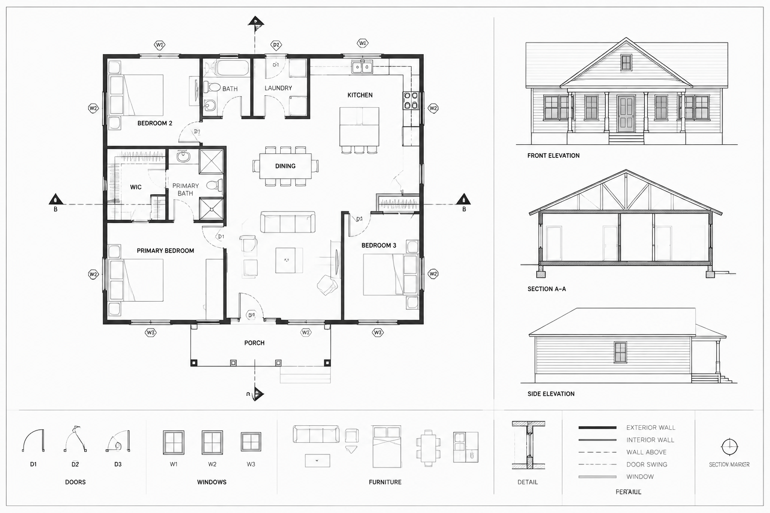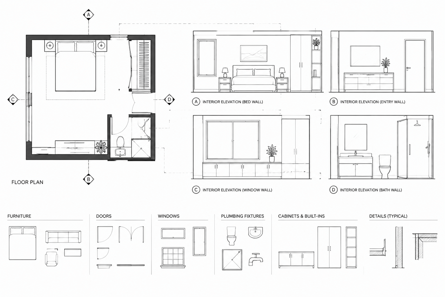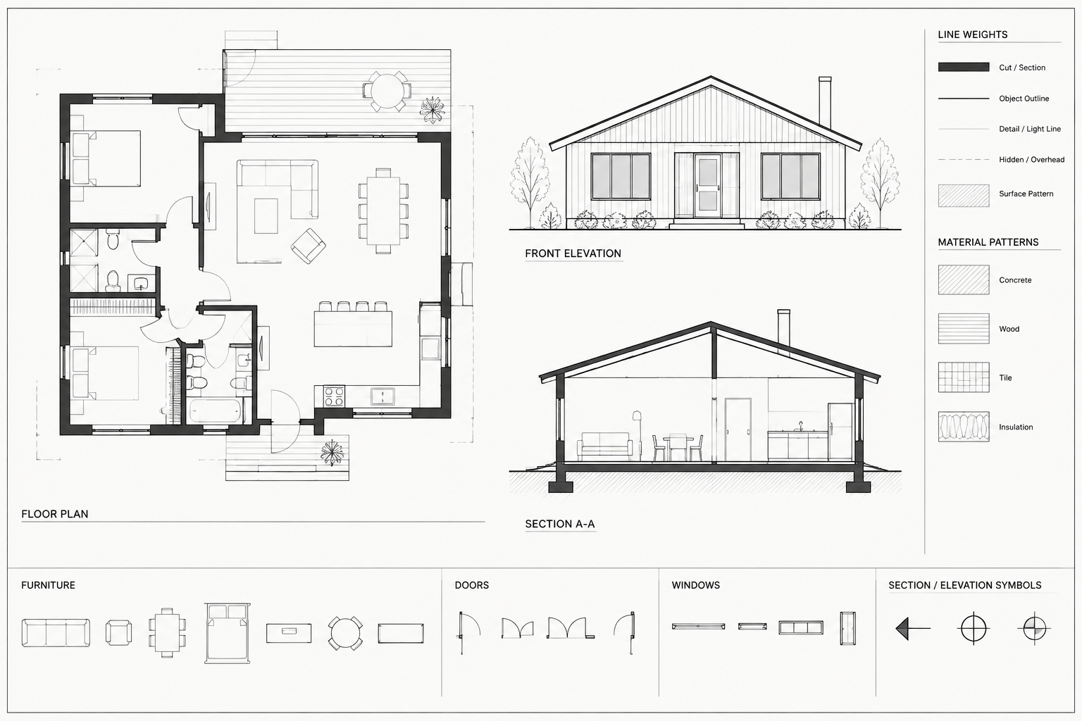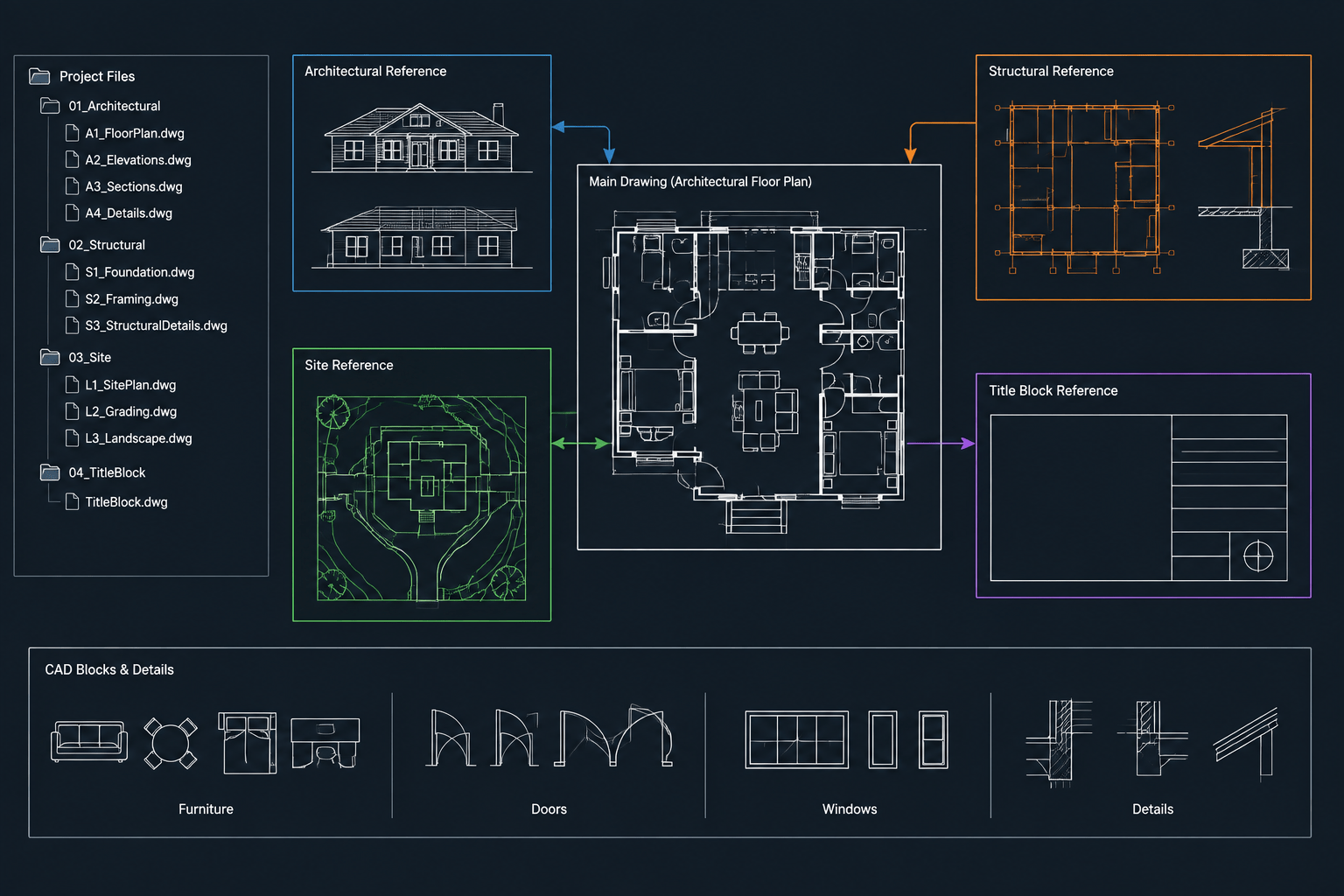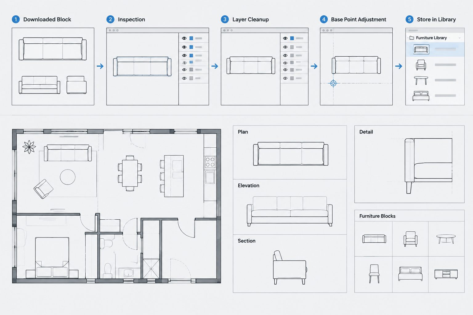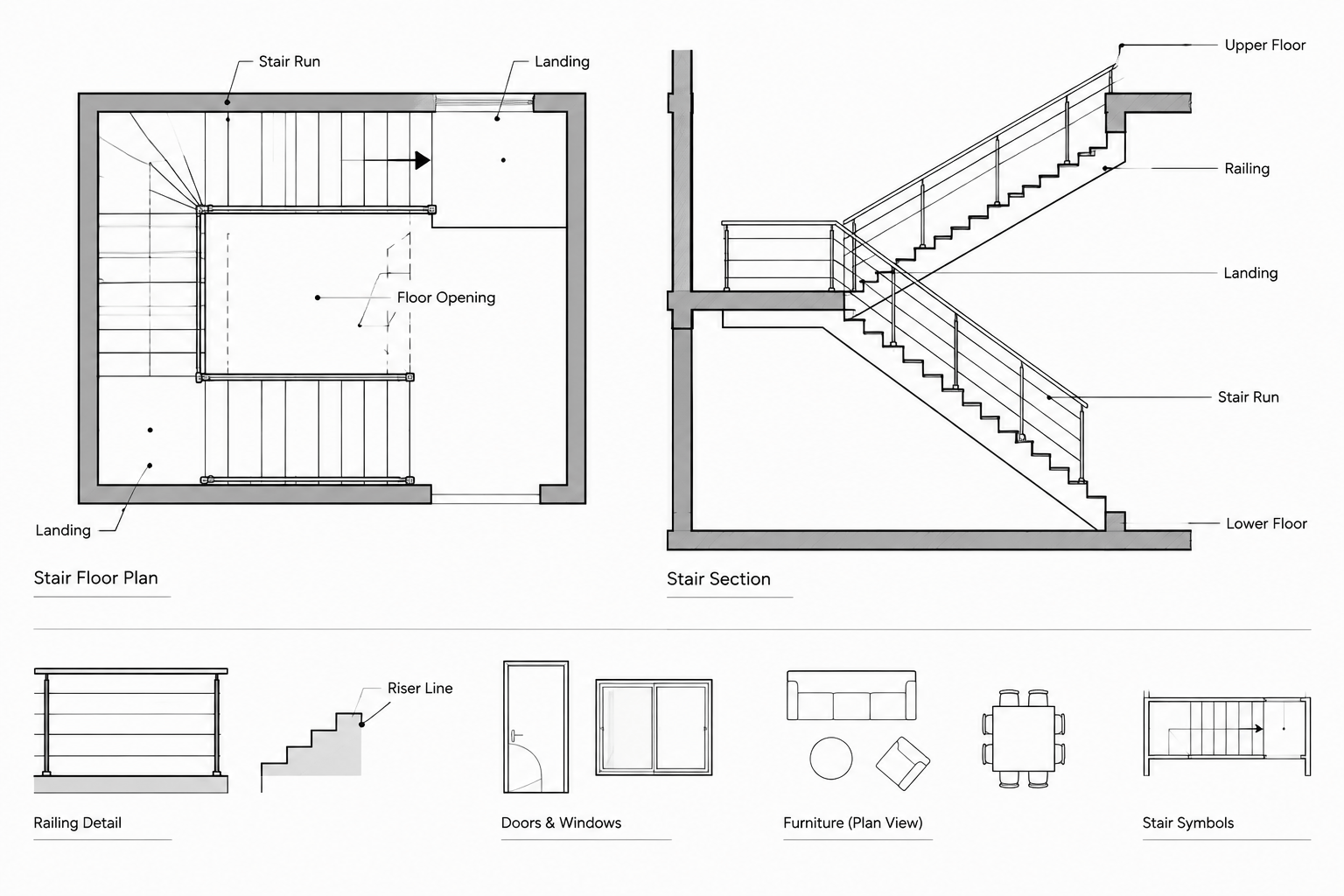
Stairs are among the most coordination-intensive elements in an architectural drawing set. A stair must work as a three-dimensional circulation system, yet it is usually documented through separate plans, sections, elevations, and details. If those views are drafted independently, mismatched risers, misplaced landings, and inconsistent railings can easily appear.
This guide explains how to draw stairs in AutoCAD or another CAD platform using a coordinated workflow. It focuses on drawing logic and quality control rather than prescribing dimensions. Actual geometry must be verified against the project design, applicable building and accessibility requirements, structural criteria, and manufacturer information.
Begin with the vertical problem
Before drawing individual treads, identify the elevations connected by the stair. Record the finished floor elevation at each level and determine whether intermediate landings or floor build-ups affect the stair geometry. The controlling vertical distance is generally the difference between the relevant finished walking surfaces.
Next, establish the intended number of risers and calculate the resulting riser height. Do not round casually. A small discrepancy repeated through an entire flight can produce a noticeable mismatch at the upper floor. Keep the calculation in the project notes or stair worksheet so another team member can review it.
Confirm the following before developing the drawings:
- Lower and upper finished floor elevations
- Number of risers in each flight
- Resulting riser height
- Tread depth or going used by the design
- Landing locations and elevations
- Stair width and edge conditions
- Floor, ceiling, beam, and roof relationships
- Required guards, handrails, and wall-mounted rails
These values are project-specific. Check them against the governing requirements for the building type and location rather than relying on a generic CAD block.
Build a simple controlling diagram
A small diagram can prevent errors before detailed drafting begins. Draw a side-view control line from the lower finished floor to the upper finished floor. Divide the rise according to the approved riser count, and project the tread sequence horizontally. This diagram becomes a geometric reference for both the stair plan and section.
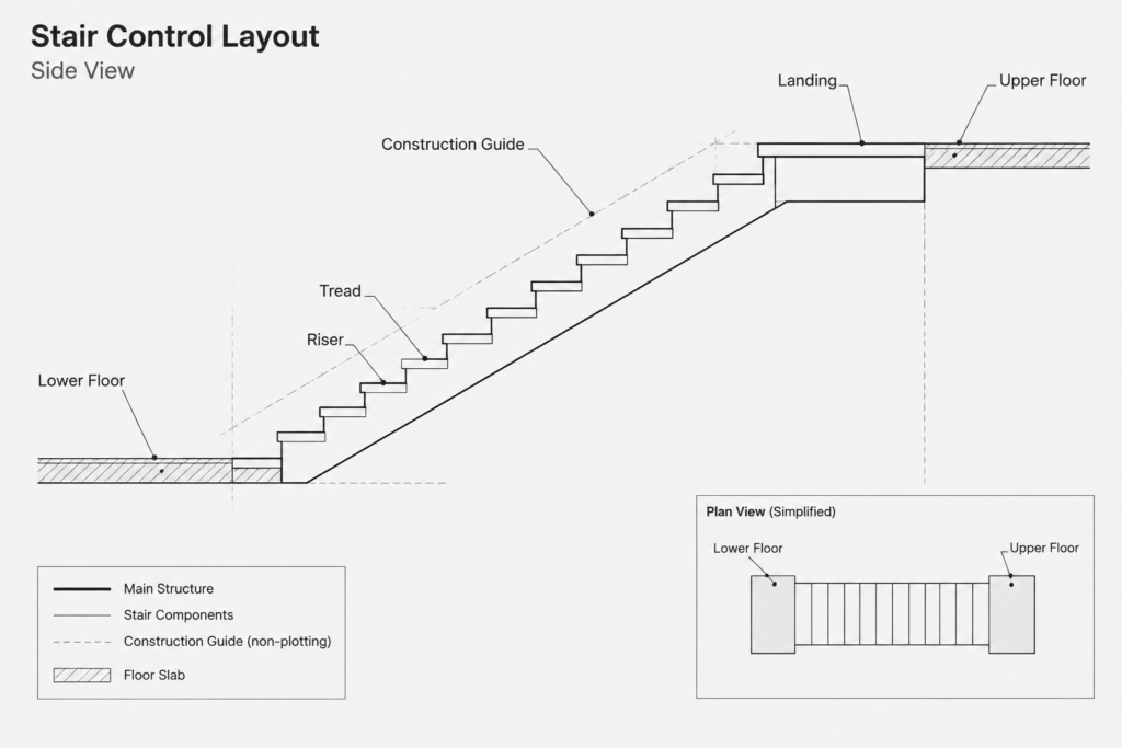
Keep controlling construction geometry on a non-plotting or clearly identified working layer. The lines should remain available while the stair is being coordinated, but they should not compete with finished drawing graphics.
Draft the stair plan from reliable references
Start the plan with the surrounding walls, floor opening, structural boundaries, and landing edges. If these elements come from referenced files, confirm that the references are positioned correctly before drawing the stair. Drafting into an outdated architectural or structural background can invalidate otherwise accurate stair geometry.
Lay out the run and riser lines
Establish the direction and overall run of each flight. Place the first and last riser deliberately, then distribute the intermediate riser lines according to the coordinated tread spacing. Avoid stretching a downloaded stair block until it fits. Nonuniform scaling can distort the relationship among treads, railings, arrows, and annotation.
For a straight flight, repeated riser lines may be generated from one verified spacing. For turning stairs, develop each flight separately and use the landing as a shared control point. If winders or curved geometry are part of the design, construct them from the project layout rather than treating them as decorative symbols.
Show the plan cut clearly
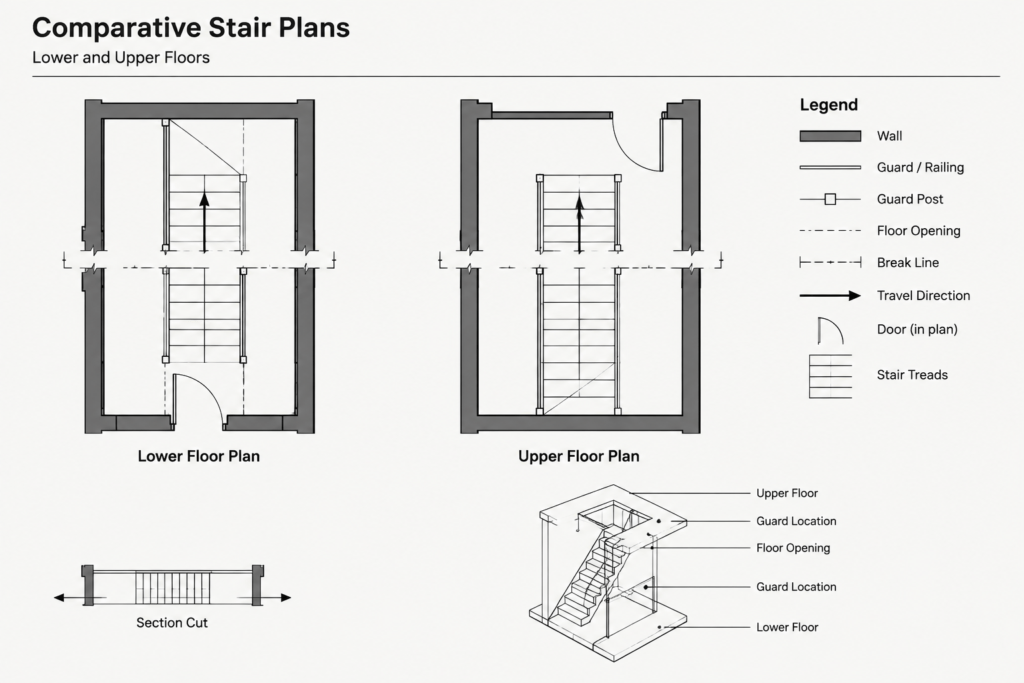
A stair plan represents what is visible relative to the drawing’s plan cut. The graphic treatment should help readers distinguish the lower visible portion of the flight from the portion continuing above or beyond the cut.
A common drawing hierarchy includes:
- Strong lines for cut walls and major cut elements
- Clear solid lines for visible stair edges and treads below the cut
- A differentiated line pattern for relevant elements above the cut
- A break line where the flight is graphically interrupted
- A direction arrow with an appropriate stair label
The exact convention should follow the office drawing standard. More important than any single graphic style is consistent use across all floor plans and enlarged stair drawings.
Coordinate the stair across levels
Do not simply copy the lower-floor stair plan to the upper floor without adjustment. The upper plan may show the opening, landing, guard, and descending flight differently because the viewing relationship has changed. Overlay or compare the plans to verify that walls, openings, stringers, and railings align vertically.
Develop the stair section from the same geometry
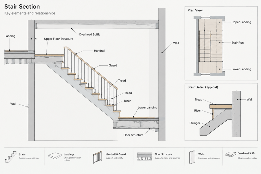
The section is the most effective view for checking whether the stair actually works. Use the same floor levels, riser count, and tread spacing established in the control diagram. Project key points from the plan where practical instead of redrawing the stair by eye.
The section should communicate the relationship among:
- Finished floors and landings
- Treads, risers, and nosings
- Floor slabs or framing zones
- Stair support or stringer geometry
- Walls and floor openings
- Ceilings, soffits, and overhead construction
- Handrails and guards
- Clear space above the walking line
The structural form should reflect the intended system. A monolithic stair, framed stair, and prefabricated stair should not be represented with the same generic section if their construction differs. Where the system has not been selected, label assumptions appropriately and avoid implying resolved construction.
Check overhead relationships
Draw the adjacent floor, landing, beam, soffit, roof slope, and ceiling conditions that could affect the stair. A plan may appear workable while the section reveals a conflict above the walking path. Treat the overhead check as part of the initial layout rather than a late annotation task.
Add railings and guards as coordinated assemblies
Railings should be drawn as building components, not as isolated lines added at the end. In plan, identify their position relative to the stair edge, wall, landing, and floor opening. In section or elevation, show how the rail follows the flight and transitions at landings.
Clarify whether a line represents a handrail, guard, wall-mounted rail, curb, stringer, or stair edge. These elements may overlap in a small-scale plan, so enlarged drawings are often needed to explain the assembly.
Posts, brackets, extensions, returns, and connections should be developed from the selected system and applicable requirements. Avoid assuming that the geometry contained in a generic railing block is suitable for the project.
Use layers and blocks without hiding design errors
Separate stair components according to their drawing function and office layer system. Useful distinctions may include stair outlines, overhead elements, railings, hidden components, annotation, dimensions, and non-plotting construction geometry. This makes it easier to control visibility between plans, sections, and presentation drawings.
Blocks can improve consistency for repeated symbols, break marks, direction arrows, or identical posts. However, the primary stair geometry should remain easy to inspect and edit. A complex anonymous block can conceal incorrect spacing or make coordination unnecessarily difficult.
Annotate what the reader needs to verify
Stair annotation should explain the design without covering the geometry. The information required varies by drawing scale and project stage, but it may include flight identification, direction of travel, riser and tread information, landing elevations, floor elevations, stair width, section references, and key material or assembly notes.
Use dimensions that support construction and checking. Avoid chains that repeat information already controlled by an overall dimension and a clear stair note. Keep plan dimensions synchronized with section information; conflicting annotations are more dangerous than missing redundant dimensions.
| Drawing view | Primary purpose | Coordination focus |
|---|---|---|
| Floor plan | Shows location, travel direction, openings, and landings | Walls, doors, circulation, stair width, and floor opening |
| Enlarged stair plan | Clarifies treads, edges, rails, and landing geometry | Riser layout, railing position, and adjacent construction |
| Section | Shows vertical geometry and construction relationships | Riser count, levels, overhead conditions, and support |
| Elevation | Shows exposed side or railing composition | Posts, guards, finishes, and transitions |
| Detail | Explains connections and material interfaces | Selected assemblies and verified product requirements |
Run a coordinated stair check
Before issuing the drawings, compare every stair view rather than reviewing each sheet in isolation. Trace one edge of the stair from the lower level through the section and onto the upper plan. Repeat the check for the opposite edge, landings, openings, and railings.
- Confirm that the riser count agrees in plan, section, and notes.
- Verify that landing elevations correspond with the level information.
- Compare the floor opening on all affected plans.
- Check walls, doors, and circulation at both ends of the stair.
- Review overhead construction in section.
- Confirm that handrails and guards continue logically through transitions.
- Remove duplicate lines and unintended block geometry.
- Test the plotted line hierarchy at the intended sheet scale.
- Identify unresolved structural or product-dependent conditions.
Treat the stair as one model expressed in several views
The most reliable stair drawings come from a single coordinated geometric idea. Plans explain horizontal relationships, sections verify vertical movement, elevations clarify exposed components, and details resolve construction interfaces. When all views are generated from shared levels and layout controls, revisions become easier to manage and drawing conflicts are less likely.
A CAD stair should therefore be more than a repeated tread symbol. It should be a traceable, checkable representation of the project’s circulation, floor openings, vertical clearances, and edge protection. Generic DWG content can help with graphic consistency, but the final stair must always be rebuilt or verified against the actual project conditions.