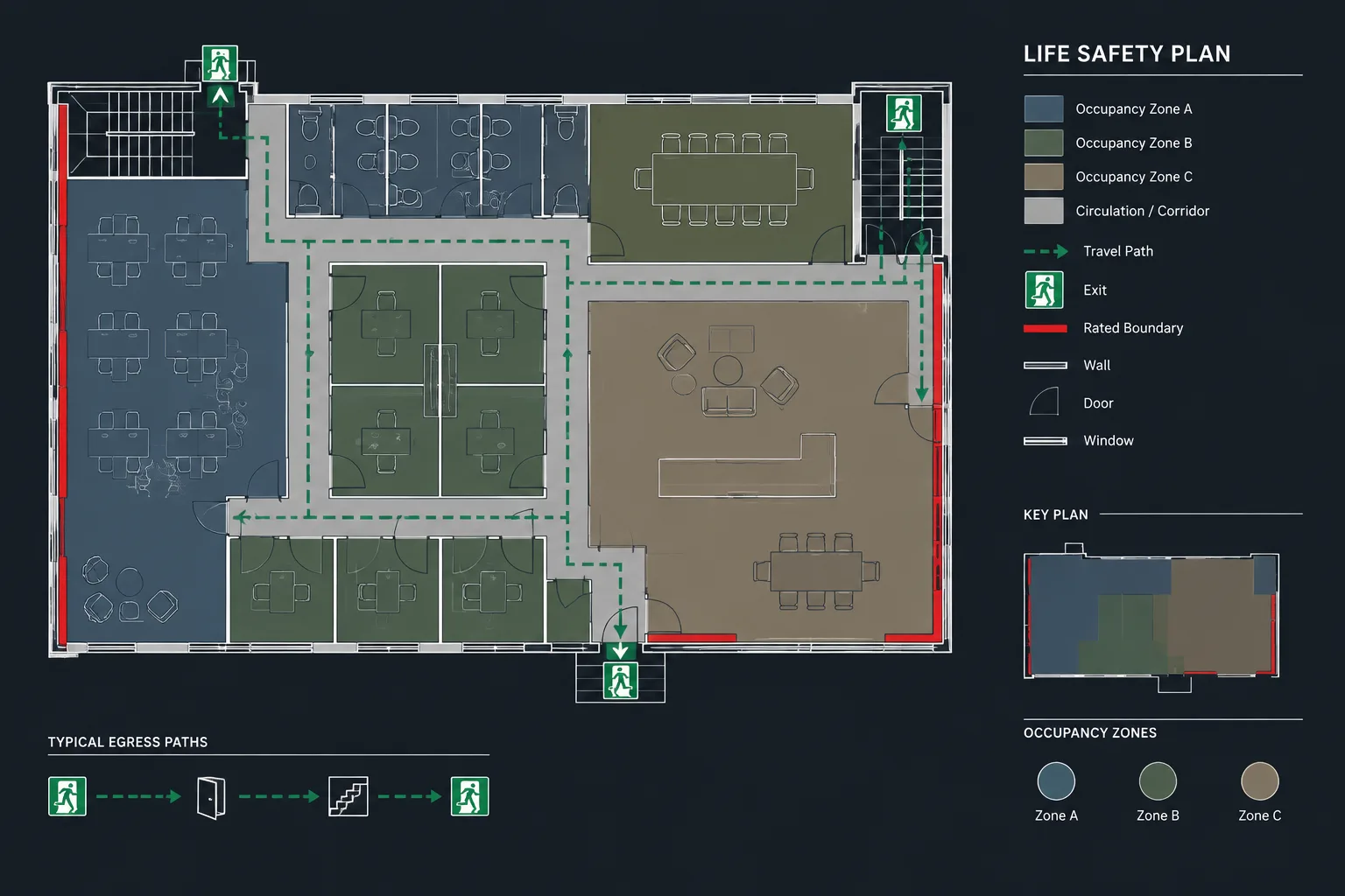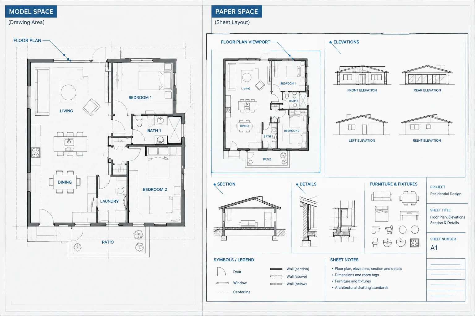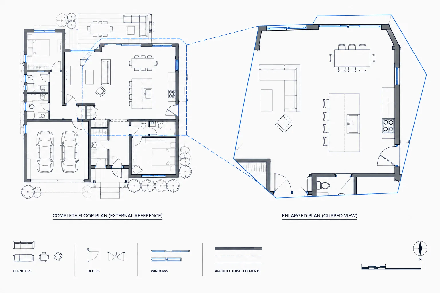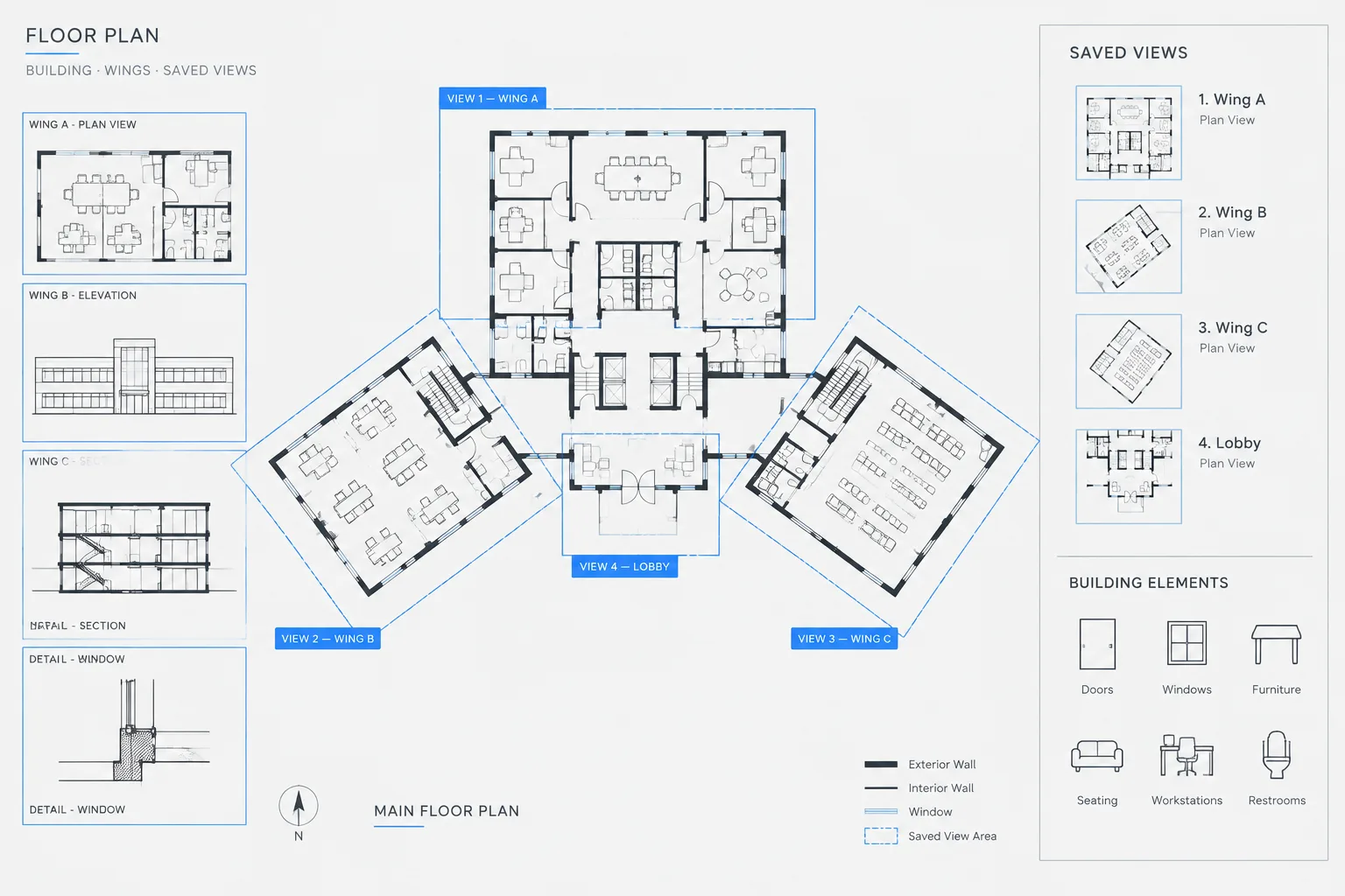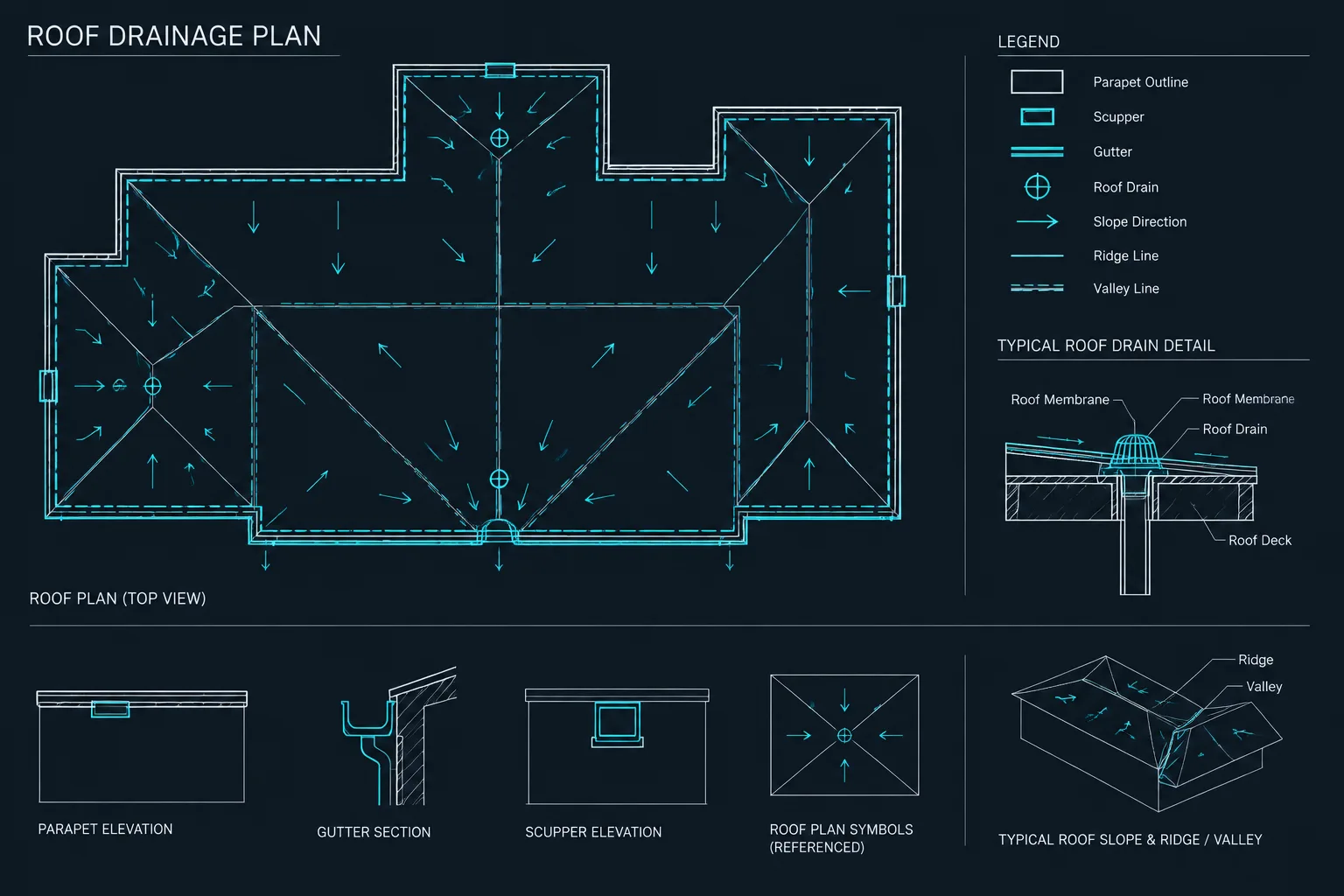
Roof drainage CAD coordination requires more than placing drains and slope arrows on a roof plan. The architectural drawing must communicate how runoff moves across each roof area, reaches a collection point, passes through or over the building envelope, and continues toward a verified discharge location.
This guide presents a practical drafting workflow for coordinating roof geometry, drainage components, consultant backgrounds, elevations, sections, and spaces below. Use it as a drawing-review framework while leaving system sizing, final elevations, structural openings, and discharge design to the responsible project professionals.
Roof drainage drawings connect architectural geometry with structural slopes, plumbing systems, civil discharge points, and exterior elevation design. A roof plan may look complete because it shows drains and slope arrows, yet still contain unresolved conflicts: water may be directed through a high point, a downspout may land over glazing, or a scupper may not align with the wall section.
Effective roof drainage CAD coordination is therefore less about placing symbols and more about documenting a continuous path for water. The drawing should help reviewers understand where water collects, how it leaves each roof area, and which disciplines must confirm the final design.
Begin with verified roof geometry
Start with the current building footprint, parapets, roof edges, penthouses, equipment curbs, skylights, canopies, expansion joints, and other major obstructions. Use coordinated architectural and structural backgrounds rather than reconstructing roof geometry from an outdated floor plan.
Before adding drainage information, verify:
- The roof boundary and all changes in roof level.
- Parapet, gutter, and open-edge conditions.
- Roof openings, equipment zones, and access paths.
- Structural framing or deck direction where it affects feasible slopes.
- Walls, shafts, ceilings, and rooms below potential drain locations.
- Exterior surfaces where downspouts, leaders, or discharge points may appear.
Keep uncertain geometry visibly separate from confirmed work. Do not turn a conceptual drain location into apparently final construction information simply by drawing it precisely.
Build a drainage logic diagram first
Before drafting detailed crickets and valleys, divide the roof into drainage areas. Each area should lead toward a known collection point or edge condition. This diagram can be a temporary CAD overlay using simple boundaries, directional arrows, and labels.
Ask three questions for every roof area:
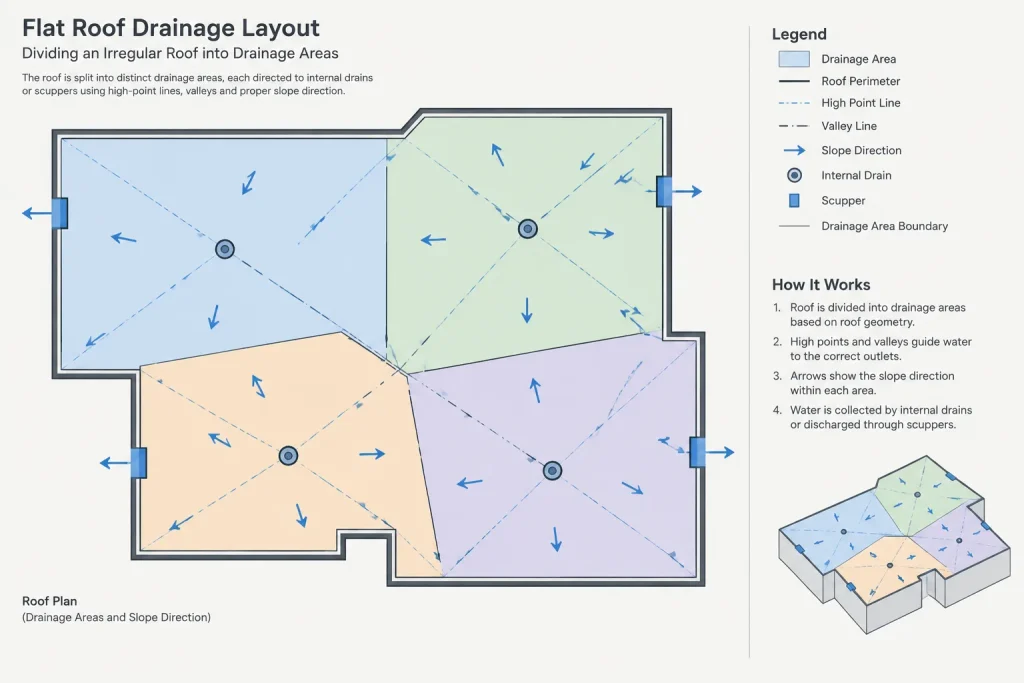
- Where is the intended low point?
- What route does water follow to reach it?
- Where does the water go after leaving the roof surface?
This early diagram reveals trapped pockets and ambiguous divides more quickly than detailed hatch patterns. It also gives the architect, plumbing consultant, structural engineer, and civil consultant a common coordination base.
Represent roof slopes clearly
Use slope arrows consistently so their direction cannot be confused with section marks, north arrows, or ordinary leaders. A project convention might show an arrow pointing downhill, but the selected convention should be defined and used throughout the drawing set.
Roof ridges, valleys, crickets, saddles, and high-point lines should be distinguishable by linework or annotation. Avoid relying only on subtle linetype differences that may disappear when plotted or reduced.
Use spot elevations as coordination evidence
Spot elevations can help demonstrate that the slope concept is geometrically possible. Place them at meaningful locations such as drains, roof corners, saddles, transitions, and changes in level. The datum and reference surface must be clear; otherwise, a precise-looking elevation may be misinterpreted.
Do not calculate or publish final elevations from assumptions. Confirm the relationship among structural deck, insulation build-up, roofing surface, and adjacent thresholds with the responsible disciplines and project details.
Draft collection and discharge components
Different roof conditions may use internal drains, scuppers, gutters, downspouts, leaders, or combinations of these elements. The roof plan should distinguish component types rather than representing every outlet with the same generic circle.
| Component | Plan information to show | Coordination to verify |
|---|---|---|
| Roof drain | Location, identifier, connected drainage area, and nearby low-point geometry | Pipe routing, structure, ceiling space, access, and drain type |
| Scupper | Wall opening, flow direction, and relationship to the low point | Parapet construction, flashing, exterior expression, and discharge path |
| Gutter | Extent, direction of flow, outlets, and transitions | Roof edge detail, fascia geometry, support, and maintenance access |
| Downspout or leader | Location, identifier, offsets, and termination intent | Elevation appearance, wall openings, foundations, and civil connection |
| Overflow route | Separate symbol or note and the intended path away from the roof | Project criteria, outlet elevation, facade impact, and safe discharge location |
Where primary and overflow components are part of the project design, show them as separate systems. Their symbols, tags, and notes should not be interchangeable. The responsible design professional must establish whether overflow provisions are required and determine their configuration.
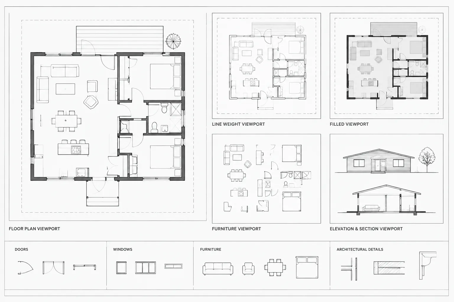
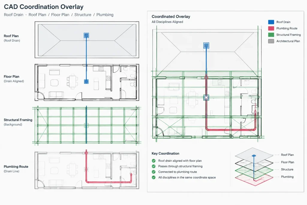
Coordinate roof plans with other views
A drainage element should be checked in more than one drawing view. A downspout that works in plan may conflict with a window head in elevation. A scupper located correctly along a parapet may be impossible to flash as drawn in section. An internal drain may align with a beam or an exposed ceiling below.
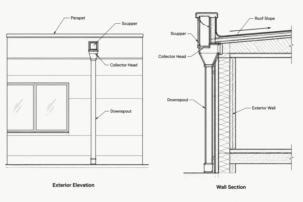
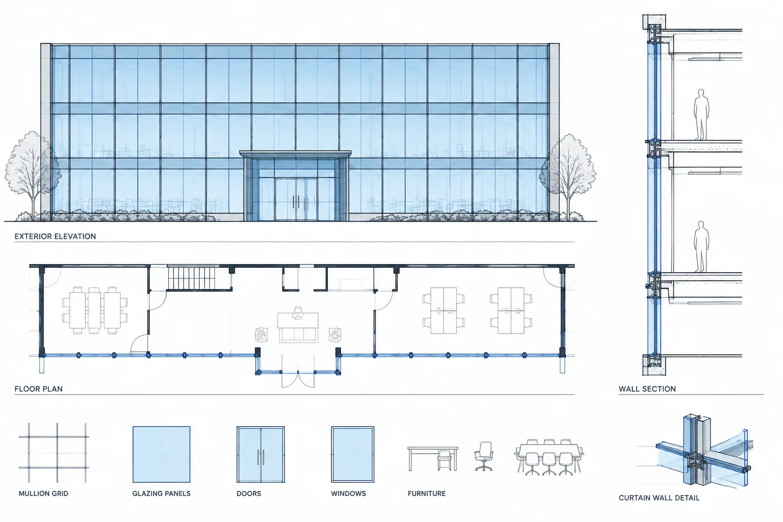
Exterior elevations
Project visible scuppers, collector heads, gutters, and downspouts onto the relevant elevations. Confirm that vertical elements do not cross openings, signs, control joints, decorative features, or entrance canopies. If a downspout changes direction, show enough information to explain the offset.
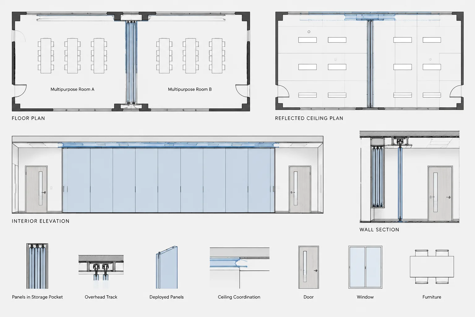
Wall sections and roof details
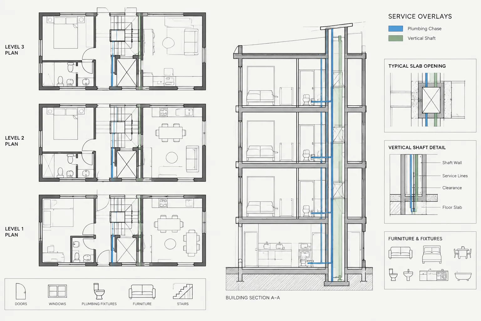
Use sections and details to clarify relationships that cannot be explained in plan, including roof build-up, parapet openings, edge flashing, gutter interfaces, and transitions between roof levels. The plan symbol, section location, and detail configuration should agree.
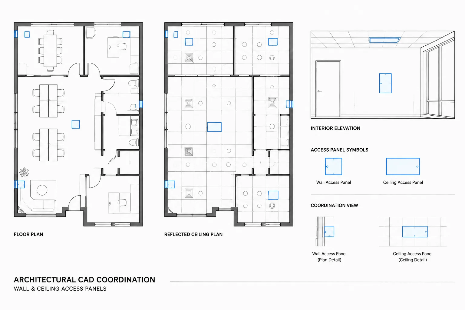
Reflected ceiling plans and floor plans below
Review internal drainage against occupied rooms, ceiling features, millwork, shafts, and access requirements below. The architectural drawing does not need to duplicate the plumbing layout, but it should not reserve a drain location that has no plausible route.
Site and civil drawings
Trace the discharge path beyond the building envelope. Determine whether the design intent is an underground connection, surface discharge, connection to a site system, or another verified condition. Avoid using a vague note such as “connect as required” when the endpoint affects paving, landscaping, entrances, or foundations.
Organize the CAD information for review
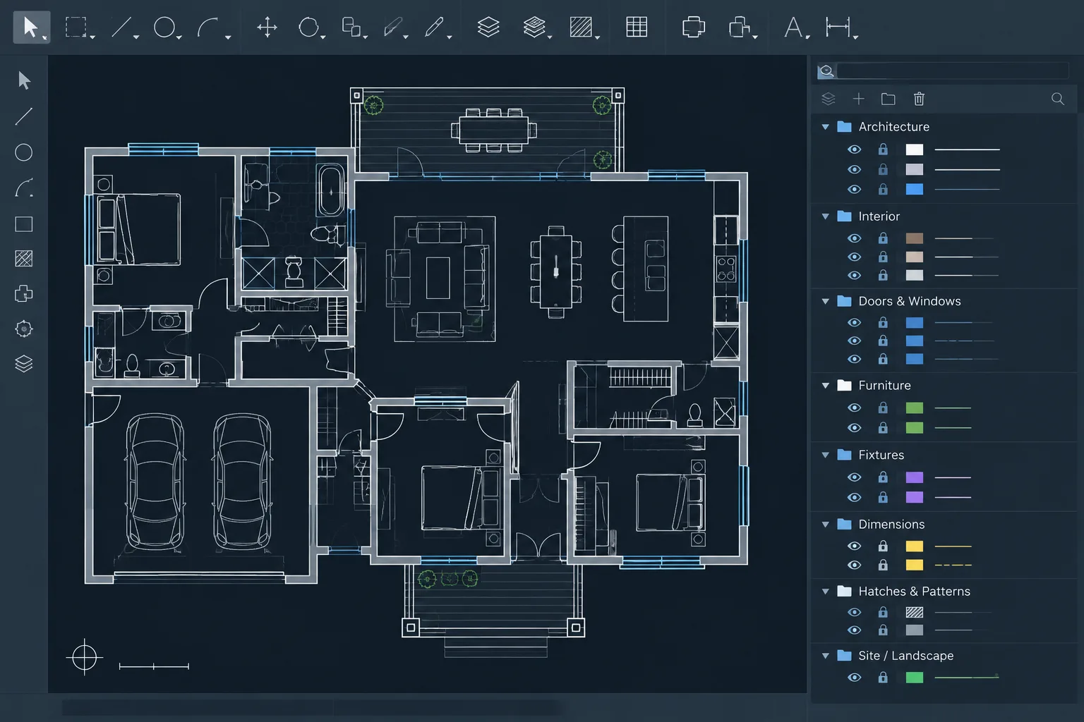
Separate drainage information into logical layers based on the project CAD standard. Useful categories may include roof boundaries, slope arrows, ridges and valleys, drains, overflow components, gutters, downspouts, spot elevations, tags, and coordination overlays.
Do not place all roof information on one layer. Reviewers should be able to isolate slope geometry, consultant backgrounds, and architectural annotations. External references should retain their discipline identity so updates can be compared without merging consultant linework into the architectural file.
Use blocks for repeated symbols, but keep them simple and readable at the intended plot scale. Attributes can support identifiers when the office workflow uses them, although visible labels should remain legible and should not depend on hidden data alone.
Apply identifiers consistently
Tags provide a practical bridge between plans, elevations, details, schedules, and consultant drawings. A drain or downspout identifier should remain consistent wherever the element appears. If the plumbing consultant owns the final designation, coordinate the architectural label rather than creating a competing naming system.
When a component moves, search for every related instance. Updating only the roof-plan symbol can leave an old downspout on the elevation or an obsolete penetration in a section.
Run a path-based quality check
Review the roof as a set of connected water paths rather than isolated symbols. Begin at a high point and visually follow the intended flow to its final discharge location.
- Does every roof area have a defined drainage direction?
- Do slope arrows agree with valleys, crickets, and spot elevations?
- Are there pockets trapped behind curbs, parapets, or expansion joints?
- Do drain locations avoid structural conflicts and have plausible routing below?
- Are visible components coordinated with elevations?
- Are scuppers and gutters supported by compatible sections or details?
- Are primary and overflow paths distinguishable where both are used?
- Does each discharge route continue into verified site or plumbing information?
- Have moved elements been updated in all related views?
- Are unresolved decisions labeled for coordination rather than shown as final?
Keep responsibility clear
Architectural roof plans often communicate surface geometry and design intent, while plumbing, structural, civil, roofing, or specialty consultants develop other parts of the system. The exact division varies by project. CAD clarity should not blur that responsibility.
Use coordination notes to identify information requiring confirmation, but avoid shifting essential design decisions into generic notes. Drain capacities, pipe sizes, overflow criteria, structural openings, and final discharge design must come from verified project requirements and the responsible professionals.
A coordinated drawing tells a complete story
A strong roof drainage plan shows more than arrows pointing toward drain symbols. It establishes drainage areas, high and low points, collection components, routes through or over the building envelope, and connections to related drawings. By tracing each path across plans, elevations, sections, and consultant backgrounds, CAD users can expose conflicts before they become difficult field conditions.
Turn coordination findings into drawing actions
Roof drainage review is most useful when each discovered conflict leads to a traceable drawing action. Record the affected component, the views in which it appears, the discipline responsible for confirmation, and whether the issue changes roof geometry, routing, exterior appearance, or detailing.
Keep unresolved items visually distinct from approved design information. A temporary overlay can show a proposed drain move or alternate downspout route without making that option look final. After a decision is confirmed, update the plan, elevations, sections, details, tags, and backgrounds that depend on it.
Review changes by dependency
A small plan adjustment may affect several related conditions. Moving a collection point can change nearby valleys, slope arrows, spot elevations, piping assumptions, ceiling coordination, facade elements, and site discharge routing. Reviewing these dependencies together is more reliable than checking each sheet independently.
- Geometry: Confirm that roof boundaries, high points, low points, and obstructions still support the intended flow path.
- Identification: Verify that the same component tag appears consistently in every relevant view.
- Building interface: Check penetrations, parapet openings, roof edges, wall assemblies, and spaces below.
- Exterior impact: Review visible outlets, gutters, leaders, offsets, and termination locations against the elevation design.
- Discharge continuity: Confirm that the documented path does not stop at the roof edge or building wall without coordinated downstream information.
Plot the drawing as part of quality control
Information that is clear at full CAD magnification may become ambiguous on a plotted or reduced sheet. Review lineweight hierarchy, overlapping symbols, label placement, arrow direction, background contrast, and the distinction between primary and overflow information. Important drainage logic should remain understandable without relying on color alone.
A final visual check should allow a reviewer to select any roof area and follow its intended drainage path across the relevant architectural and consultant drawings. If that path becomes uncertain, disappears between views, or ends at an unverified location, the coordination is not complete.
Roof Drainage CAD Coordination FAQ
What should an architectural roof drainage plan communicate?
It should communicate roof boundaries, changes in level, drainage direction, collection points, relevant high and low points, component identifiers, and connections to related elevations, sections, details, and consultant information. It should also distinguish confirmed design information from unresolved coordination items.
Why are slope arrows alone not enough?
Slope arrows indicate direction but do not necessarily prove that water can reach the intended outlet. Valleys, crickets, curbs, parapets, roof-level transitions, and spot elevations provide the supporting geometry needed to evaluate the path.
How should drains and downspouts be organized in CAD?
Use consistent symbols, identifiers, and logical layers that allow drainage components and annotations to be isolated for review. Repeated symbols may be managed as blocks, but visible labels should remain readable and coordinated with consultant naming.
Which drawings should be checked when a drainage component moves?
Check the roof plan along with affected elevations, wall sections, roof details, reflected ceiling plans, floor plans below, and site or civil information. Also review associated tags, slope geometry, penetrations, and discharge routes.
How should uncertain drain locations be shown?
Keep proposed or unverified locations separate from confirmed construction information through a clear overlay, status note, or office-approved graphic convention. Precision in CAD should not imply that an unresolved location has been approved.
Who determines drainage capacity and final system configuration?
The responsible design professionals must determine capacities, routing, overflow criteria, structural openings, and final discharge design using verified project requirements. Architectural CAD documentation should coordinate and communicate that information without inventing it.