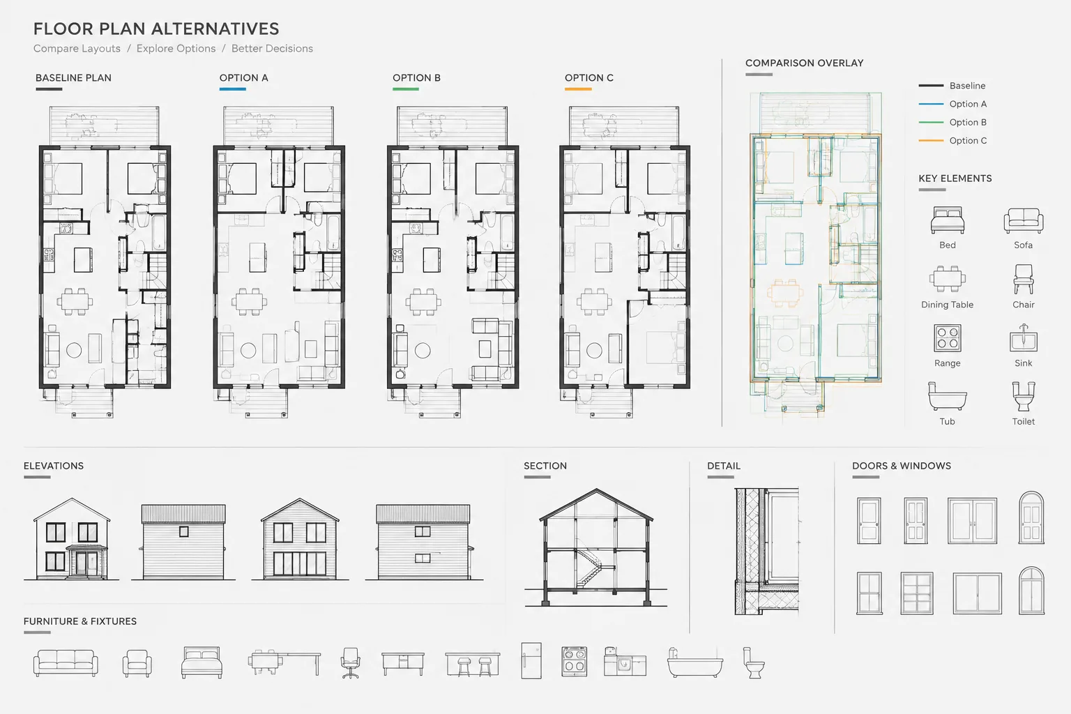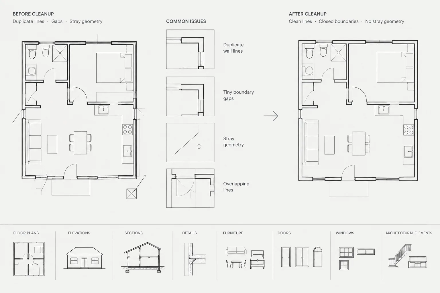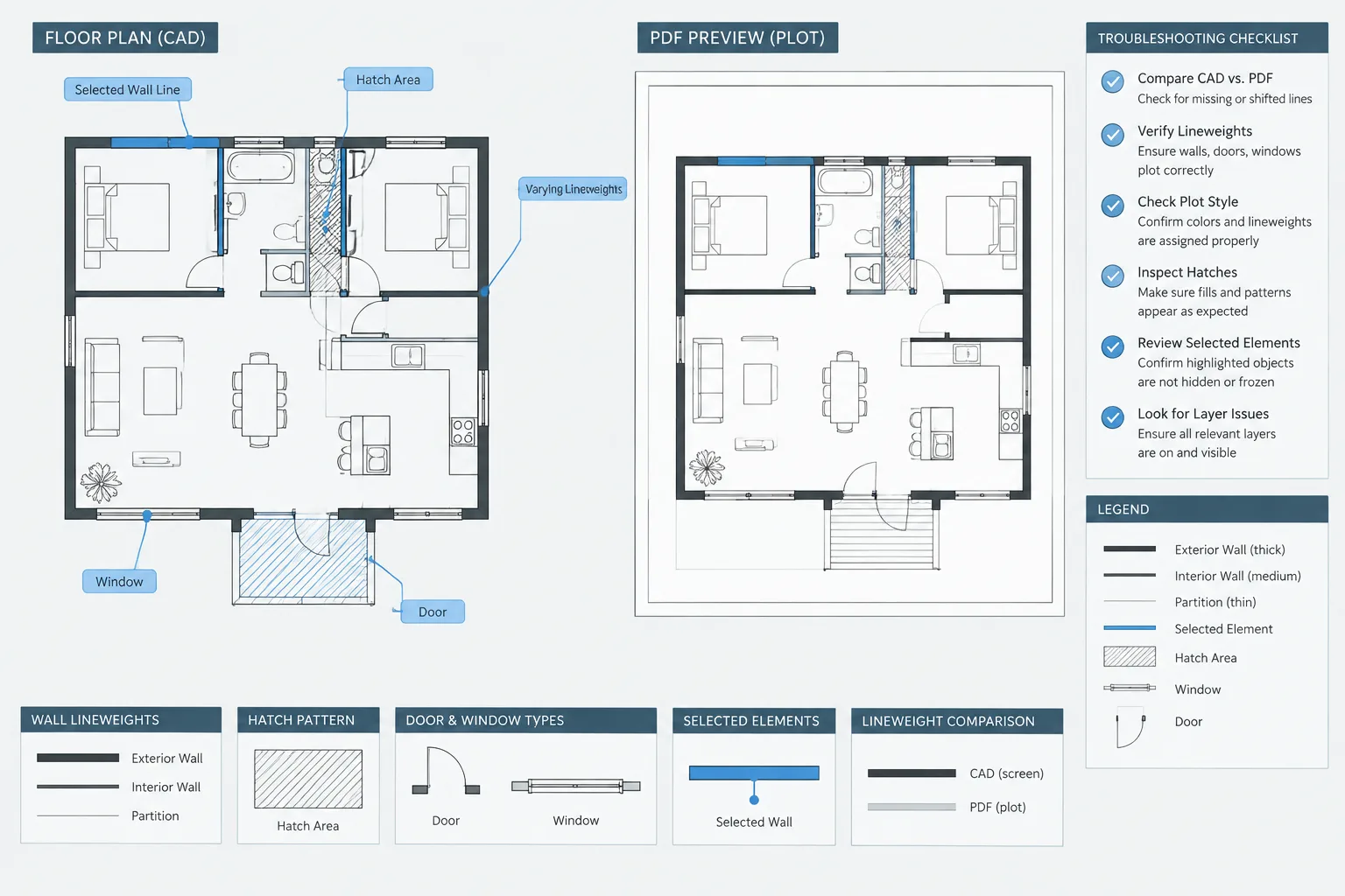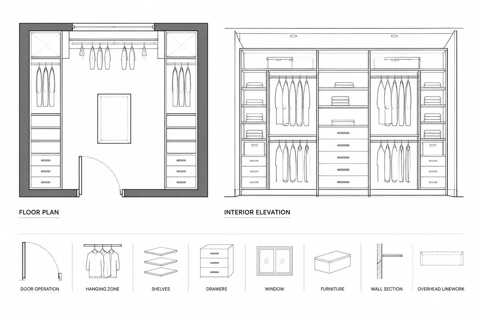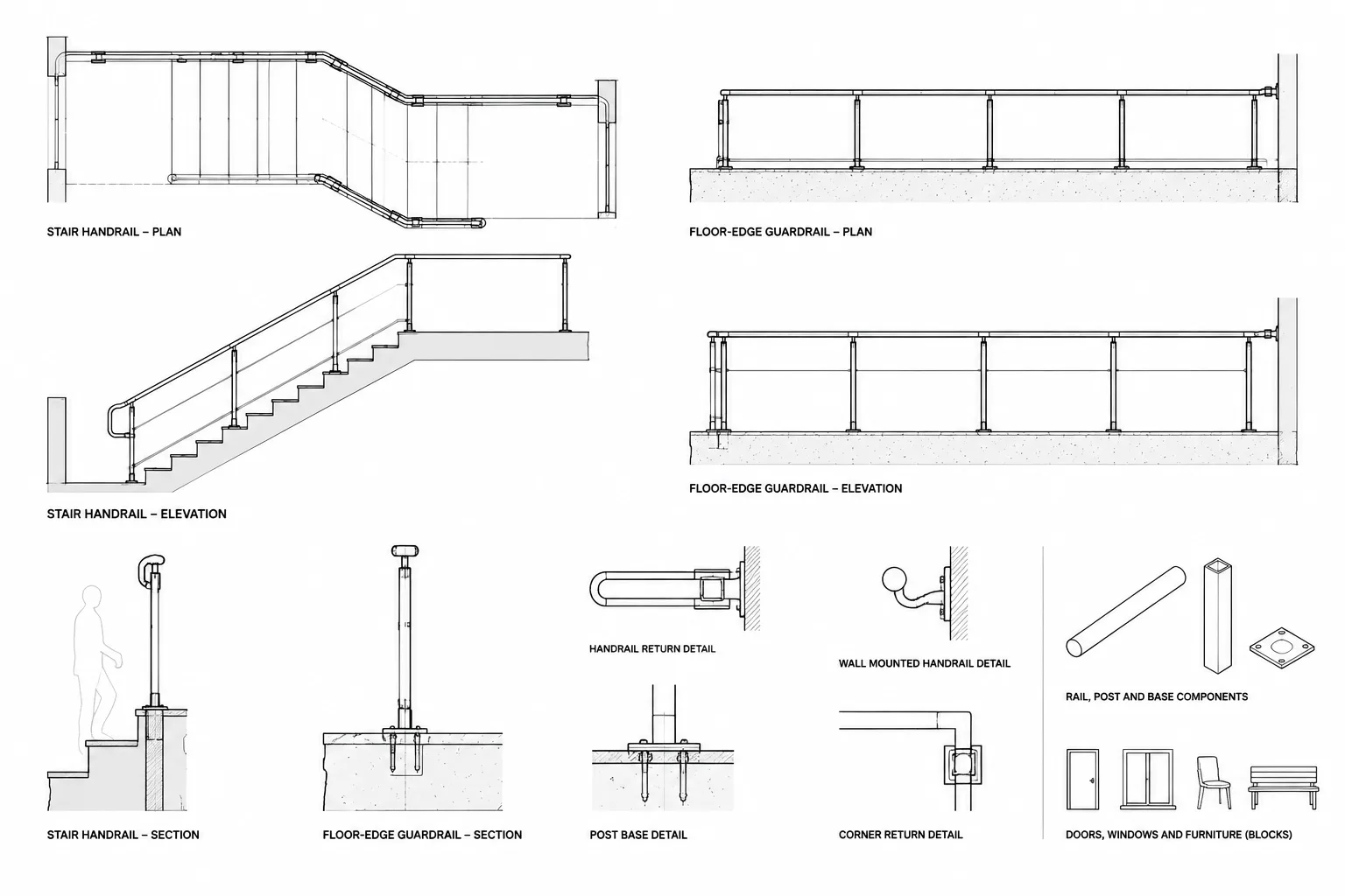
Effective handrail and guardrail CAD drafting requires more than placing a standard railing symbol beside a stair or floor edge. The assembly must remain consistent as it moves between level and sloped surfaces, changes direction, meets walls, crosses drawing cut planes, and connects to supporting construction.
This guide explains how to treat the railing as a coordinated architectural system. It focuses on establishing controlling geometry, distinguishing graspable rails from edge protection, aligning information across views, organizing reusable CAD content, and identifying conditions that require enlarged details. Dimensions, code criteria, structural connections, and product requirements must always be verified for the applicable project.
Handrails and guardrails often appear simple in a floor plan, but they become coordination-intensive when viewed across plans, elevations, sections, and details. A single railing assembly may interact with stair geometry, ramps, landings, floor edges, walls, structure, finishes, and circulation space. If these relationships are not resolved in the CAD drawings, the result can be conflicting views or unclear construction intent.
A reliable handrail and guardrail CAD drafting workflow begins with geometry rather than decoration. Establish the walking surface, protected edge, supporting construction, and termination conditions before adding posts, brackets, pickets, panels, or material hatches. Applicable codes, accessibility criteria, project specifications, and manufacturer requirements must be verified separately for each project.
Distinguish the Handrail from the Guardrail
Although the terms are sometimes used interchangeably in casual discussion, a handrail and a guardrail perform different functions. A handrail is intended to be grasped for support along a stair, ramp, or walking route. A guardrail or guard protects an exposed edge where a change in level creates a fall hazard. One assembly may perform both functions, but the drawings should still communicate each component clearly.
This distinction matters in CAD because the two elements may follow different paths. A guard may continue around an open landing while the graspable rail returns to a wall or terminates at a specific point. Likewise, a wall-mounted handrail can occur without a guard. Avoid representing every condition with one generic pair of parallel lines.
| Element | Primary drafting concern | Views that usually clarify it |
|---|---|---|
| Handrail | Continuous grasping path, extensions, returns, and wall clearance | Plan, elevation, and enlarged detail |
| Guardrail | Protected-edge path, top profile, infill, posts, and attachment | Plan, elevation, section, and connection detail |
| Posts or brackets | Spacing logic and conflicts with structure or finishes | Plan, elevation, and mounting detail |
| Infill | Panel limits, picket layout, joints, and edge conditions | Elevation and section |
| Mounting construction | Substrate, edge distance, waterproofing, and finish interfaces | Section and enlarged detail |
Start with the Controlling Architectural Geometry
Do not begin by inserting a generic railing block. First verify the geometry that controls the assembly:
- Stair runs, landings, nosings, and changes in direction
- Ramp edges, landings, and adjacent walls
- Floor openings, balconies, mezzanines, and raised platforms
- Wall faces and finish build-ups
- Slab edges, curbs, stringers, and other supporting construction
- Door swings, access panels, equipment zones, and circulation paths
Reference these elements from the coordinated architectural background rather than recreating them inside a railing block. If the stair or slab edge changes, the railing path should be easy to update without editing unrelated nested geometry.
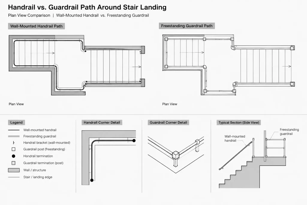
Build a Clear Plan Representation
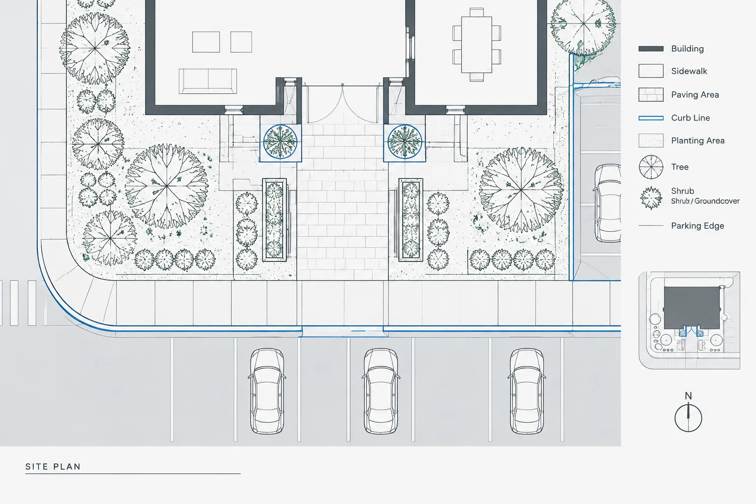
In plan, draw the rail path according to its relationship with the floor plan cut plane. Portions cut by the plan may require stronger graphic emphasis than components seen beyond or overhead. Use the project’s established lineweight and linetype hierarchy rather than relying on color alone.
A useful plan representation may include the top rail or handrail path, post locations, wall brackets, changes in direction, and limits of the guard. Show only the infill needed to explain the design. Drawing every picket in a small-scale plan can create visual noise and make dimensions difficult to read.
Resolve Corners and Terminations Explicitly
Corners, returns, and endpoints are common sources of ambiguity. At each termination, determine whether the rail:
- Returns to a wall, post, floor, or supporting member
- Continues around a landing or floor opening
- Transitions between a wall-mounted and freestanding condition
- Meets another rail at a corner or change in slope
- Stops near a door, column, or other obstruction
Do not allow two lines simply to overlap at a corner without showing how the assembly connects. Even a small enlarged plan can communicate the intended relationship better than a crowded general plan.
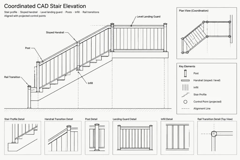
Develop Elevations from the Same Control Points
Once the plan path is stable, project key locations into the elevation. Use shared control points for posts, corners, landings, slope transitions, and terminations. This reduces the chance that a post shown in plan disappears or shifts in elevation.
In a stair elevation, establish the stair profile before drawing the handrail. The rail should respond to the actual run, landing, and transition geometry. At floor edges and balconies, coordinate the guard elevation with slab edges, finish surfaces, curbs, and adjacent wall conditions.
Show enough repetition to explain the infill system, but avoid manually drawing large quantities of repeated elements without a clear editing strategy. Repeated CAD content can be organized as blocks or other reusable geometry when appropriate. Keep unique end panels and corner conditions separate if they require different editing.
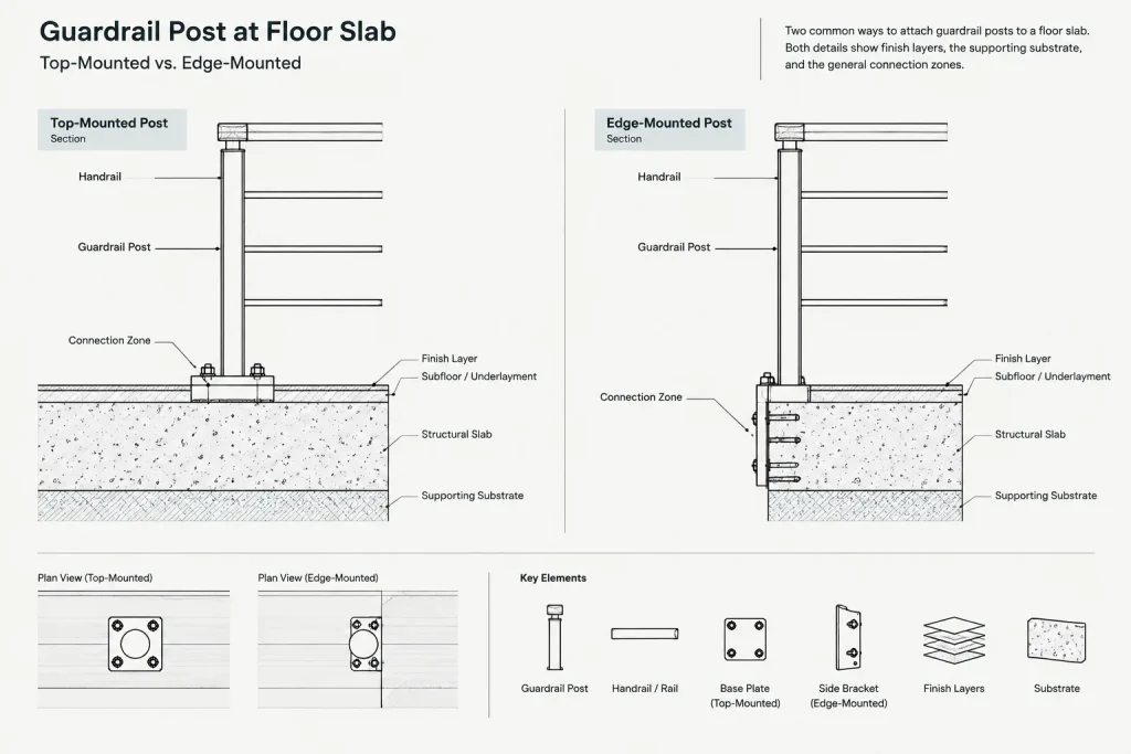
Use Sections to Explain Position and Attachment
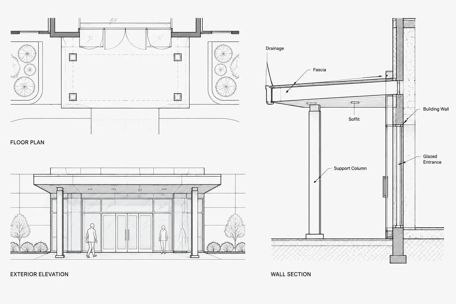
Plans and elevations describe the railing path, but sections explain where the assembly sits in relation to the building. A typical section can clarify whether posts are mounted on top of a slab, attached to its face, integrated with a stair stringer, or supported by another element.
Include the surrounding construction needed to understand the interface. Depending on the condition, that may include the structural substrate, floor finish, wall finish, waterproofing zone, curb, fascia, or edge trim. Avoid drawing a connection that appears to attach only to finish material unless that is genuinely the coordinated design.
Architectural drawings should communicate design intent without inventing structural performance. Connection plates, anchors, welds, fasteners, and reinforcement must be coordinated with the responsible engineer, fabricator, manufacturer, and project specifications. Clearly identify delegated or deferred design responsibilities when the project documentation requires them.
Organize Railing Geometry on Purposeful CAD Layers
Railing content should fit the project’s broader layer system. Separate components only when that separation improves visibility control, plotting, coordination, or editing. A practical organization may distinguish primary railing geometry, overhead or beyond elements, annotation, centerlines, and detail hatches.
Avoid placing an entire railing detail on a single miscellaneous layer. Also avoid excessive fragmentation in which every physical component receives a layer with no drawing-management benefit. The goal is predictable control across floor plans, enlarged plans, elevations, and details.
Coordinate Dimensions and Notes
Dimension the controlling relationships rather than every visible component. Useful references may include the railing path relative to an edge, limits of an assembly, post layout control points, and relationships to walls or openings. Detailed fabrication dimensions should not conflict with information assigned to shop drawings or specialist design documents.
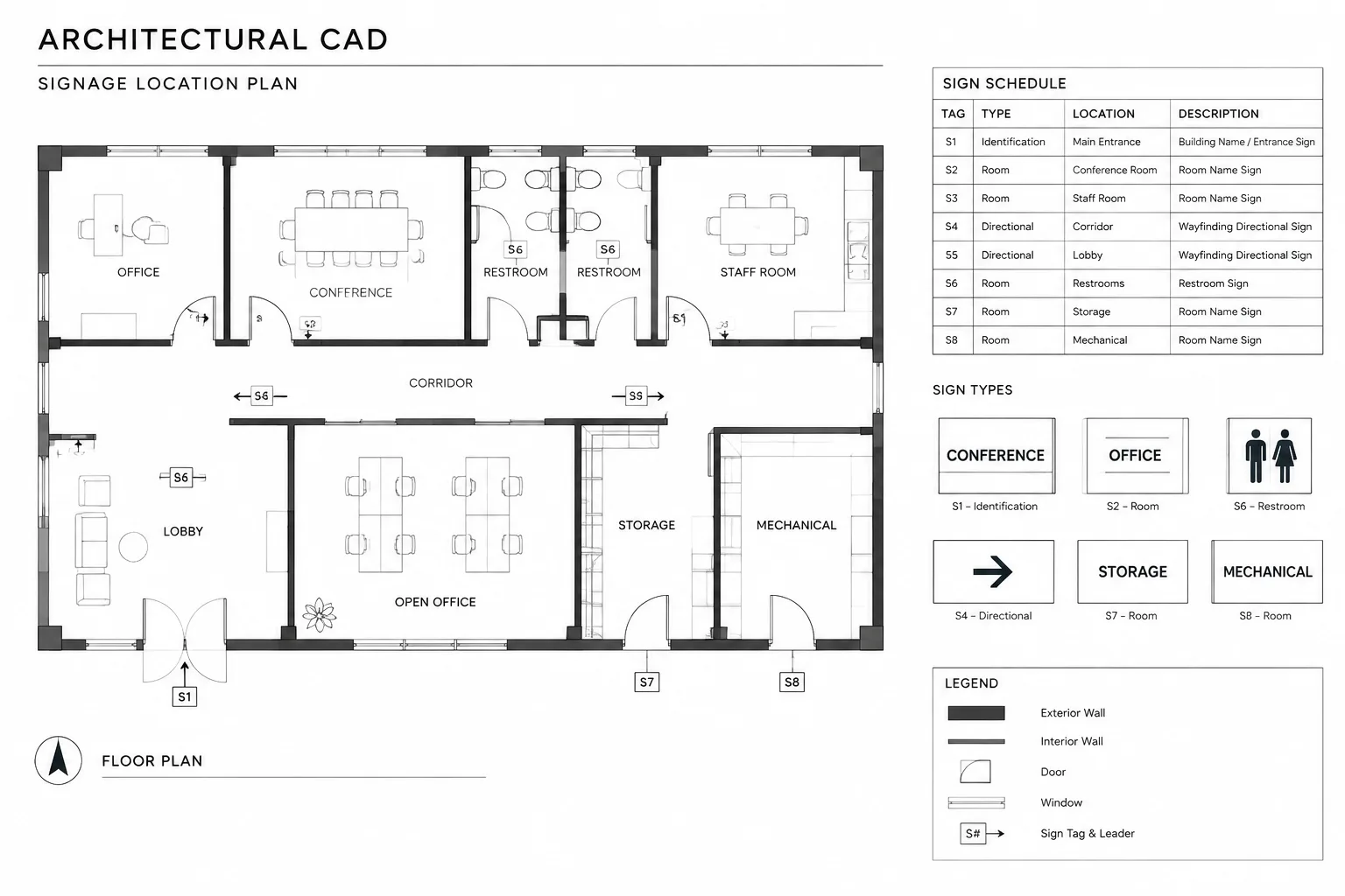
Notes should identify the assembly and important interfaces without attempting to replace the detail. Coordinate terminology among tags, schedules, specifications, and drawing notes. If several railing types occur, use stable type identifiers and confirm that the same identifier does not describe different configurations.
Create Typical Details Without Hiding Exceptions
Typical details are useful for repeated conditions, but they should not be applied indiscriminately. A top-mounted interior guard, an exterior edge-mounted guard, and a wall-mounted stair handrail may require different details even if they share a finish.
Before referencing a typical detail, compare the actual condition against its assumptions:
- Is the supporting substrate the same?
- Is the assembly interior or exposed to weather?
- Does the floor or wall finish change?
- Is the rail level, sloped, curved, or transitioning?
- Does the termination match the typical condition?
- Are nearby doors, joints, drains, or penetrations present?
Create a separate detail when an exception changes construction intent. Do not force an unusual condition to reference a typical detail merely to reduce the number of drawings.
Run a Cross-View Coordination Check
Before issuing the drawings, review each railing assembly as one continuous object moving through the drawing set. Trace it from its beginning to its end and compare every related view.
- Confirm that plan, elevation, and section show the same path and termination.
- Check that post locations align across views.
- Verify transitions at stair landings, corners, and changes in slope.
- Look for conflicts with doors, glazing, columns, wall finishes, and equipment.
- Confirm that tags and detail references point to the intended conditions.
- Review lineweights, hidden lines, overhead graphics, and break symbols at plotted scale.
- Confirm that project-specific safety and accessibility criteria have been checked by the responsible design team.
Well-coordinated handrail and guardrail CAD drafting is less about drawing more lines and more about showing the right relationships. By controlling the path in plan, projecting consistent points into elevations, and detailing the supporting interfaces in section, the drawings can remain clear even when the assembly changes direction, slope, material, or mounting condition.
A Practical CAD Review Sequence
A focused review is easier when the assembly is checked in the same order that its geometry is developed. Begin with the architectural background, follow the rail path, and then inspect the interfaces that cannot be understood from the general plan alone.
- Verify the background: Confirm that the referenced stair, ramp, landing, wall, slab edge, and finish geometry reflects the current design.
- Trace the path: Follow each handrail and guard from its beginning to its termination without assuming that a typical condition applies throughout.
- Compare views: Check corners, posts, slope changes, mounting locations, and endpoints in the plan, elevation, and section.
- Review drawing hierarchy: Make sure cut, beyond, overhead, hidden, and annotation graphics remain understandable at the intended plotted scale.
- Inspect interfaces: Look closely at doors, glazing, columns, joints, finishes, waterproofing zones, and supporting construction.
- Resolve exceptions: Add an enlarged view or condition-specific detail when a typical reference does not communicate the actual configuration.
Separate Design Intent from Fabrication Information
Architectural CAD drawings should define the intended location, extent, appearance, transitions, and relationship to the building. They should not imply that an uncoordinated anchor, plate, weld, fastener, or substrate connection has been structurally verified.
Keep the division of responsibility visible in the drawing set. Architectural views can establish control points and interfaces, while engineering, manufacturer, fabricator, shop drawing, and specification information can address assigned performance and fabrication requirements. Where these sources overlap, use consistent type names and detail references so that later coordination does not produce competing instructions.
Use Markups to Track Cross-View Changes
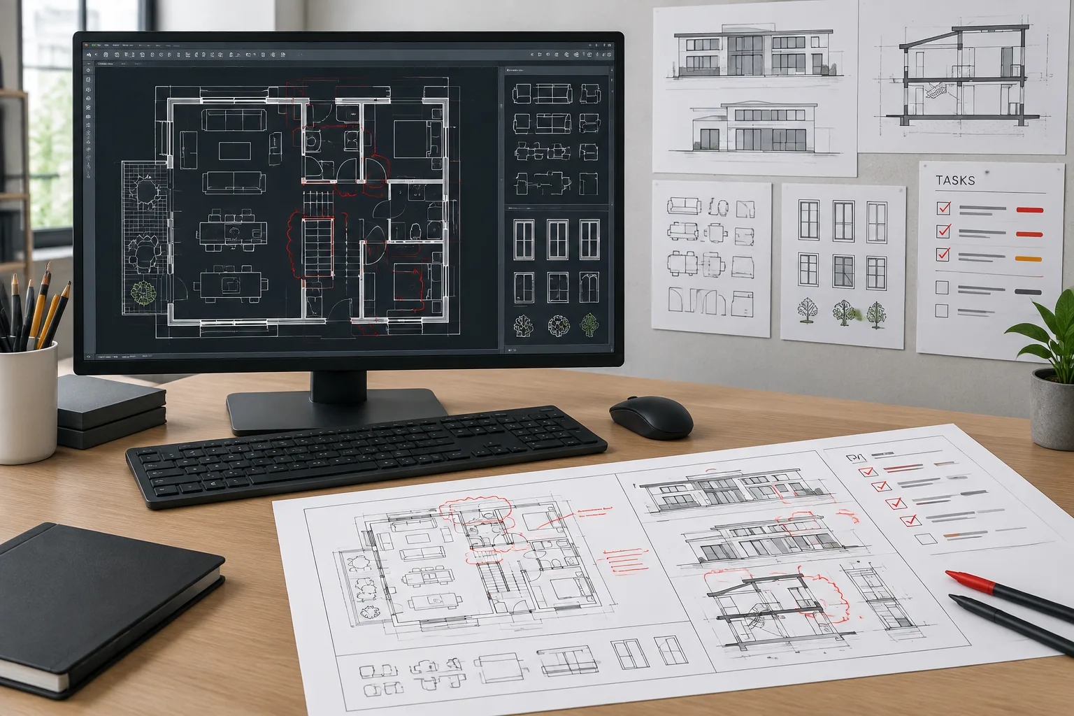
When a railing path changes, mark every affected view rather than correcting only the drawing where the issue was discovered. A revised landing, wall face, slab edge, or termination can affect plans, interior elevations, building sections, enlarged details, tags, and schedules. Recording these dependencies during review helps prevent an outdated view from remaining elsewhere in the set.
Frequently Asked Questions
Should handrails and guardrails use the same CAD block?
Not automatically. They have different functions and may follow different paths. Reusable blocks can be helpful for repeated components, but the overall geometry should remain adaptable to the actual stair, landing, wall, and floor-edge conditions.
Which view should control the railing layout?
No single view explains every condition. The plan usually controls the horizontal path, the elevation communicates profile and repetition, and the section clarifies mounting and relationships to surrounding construction. Shared reference points should keep all views coordinated.
How much railing infill should appear in a floor plan?
Show enough to identify the system and its limits without overwhelming the plan. Detailed panel, picket, or joint layouts are often clearer in elevations and enlarged details. The appropriate graphic density depends on the drawing scale and purpose.
When does a railing condition need an enlarged detail?
Use an enlarged detail when a corner, termination, transition, mounting interface, finish condition, or nearby obstruction cannot be communicated clearly in the general views. Details are especially useful when a condition differs from the project’s typical assembly.
How should railing changes be coordinated in CAD?
Update the controlling path first, then review every dependent plan, elevation, section, detail, tag, note, and schedule entry. Check referenced backgrounds and reusable content so that outdated geometry is not retained in another view.
Can architectural drawings define railing connections?
They can communicate intended mounting locations and surrounding interfaces, but connection performance and fabrication requirements must be coordinated with the responsible engineer, manufacturer, fabricator, and project specifications.