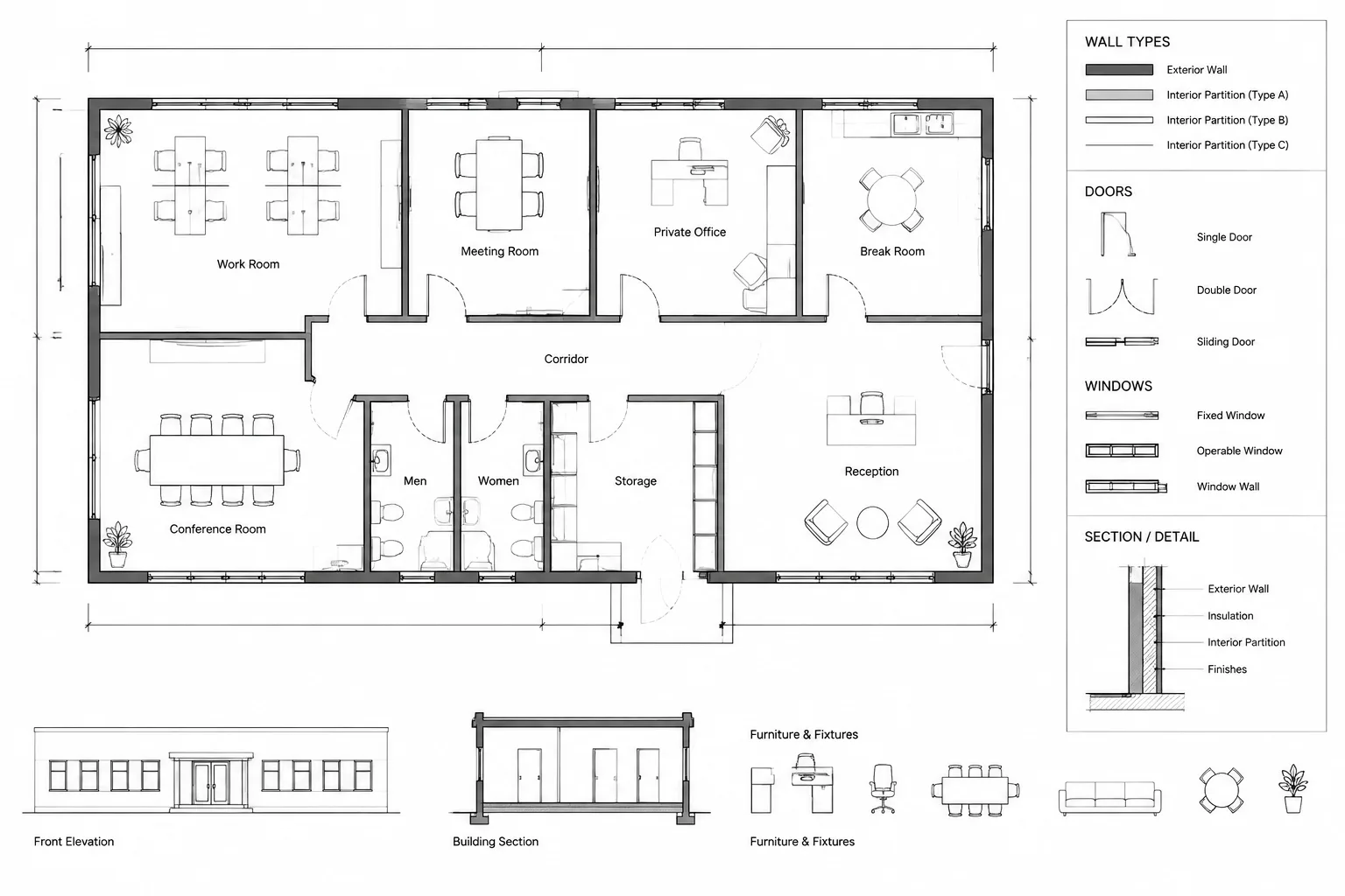
Drafting interior partitions is a control problem before it is a linework problem. The drafter must identify which references govern the layout, which wall face or centerline is being located, and which drawing owns the detailed dimensions.
This guide explains how to establish that control in CAD while keeping partitions coordinated with doors, room boundaries, ceilings, finishes, furniture, structure, and consultant information.
An interior partition layout plan defines much more than the location of walls. It establishes room geometry, circulation, door openings, wall types, built-in elements, and the reference points used by dimensions and related drawings. If the partition plan is poorly organized, small changes can spread inconsistencies into reflected ceiling plans, finish plans, furniture layouts, elevations, and consultant backgrounds.
A reliable workflow begins with coordinated references and a clear wall-location strategy. The goal is not simply to draw parallel lines. It is to create plan geometry that remains understandable, editable, and coordinated as the design changes.
What an Interior Partition Layout Plan Communicates
Depending on the project and drawing set, partition information may appear on the main floor plan or on a dedicated layout plan. In either case, the drawing typically communicates:
- The location and configuration of interior walls.
- Wall type references and changes in partition construction.
- Door, glazed opening, borrowed-light, and access-panel locations.
- Room relationships, circulation paths, and major clear zones.
- Critical dimensions needed to establish the layout.
- Connections to columns, exterior walls, shafts, stairs, and service spaces.
- References to enlarged plans, sections, elevations, and details.
The plan should describe design intent without attempting to replace every detail drawing. A wall junction that requires a special support, finish transition, or movement condition should be referenced rather than overloaded with notes at the floor-plan scale.
Start with a Controlled Reference Background
Before drawing partitions, verify the files that control their location. These may include a survey or shell plan, structural grid, column layout, exterior wall geometry, core layout, floor openings, stairs, elevators, and major building services.
Use external references when the project workflow supports them. Avoid copying structural or consultant geometry into the architectural file unless there is a specific reason to create a controlled snapshot. Duplicated background information can become outdated while still appearing authoritative.
Confirm the drawing units, project origin, floor level, and reference rotation before layout work begins. A partition plan built on a shifted or incorrectly scaled background may look correct in isolation but fail when combined with other disciplines.
Separate fixed and flexible constraints
Not every reference has the same level of authority. Structural columns, shafts, exterior enclosure geometry, and major openings may be relatively fixed. Furniture, casework, and room divisions may still be developing. Distinguishing these categories helps the drafter avoid treating temporary design studies as permanent control geometry.
Choose a Consistent Wall-Location Strategy
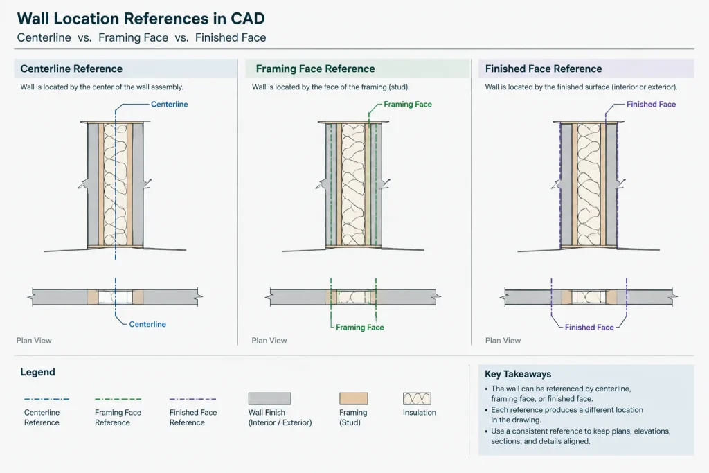
A common source of drafting error is switching unpredictably between wall faces, wall centerlines, and finish faces. Decide what controls each partition before placing it.
| Reference method | Useful application | Coordination concern |
|---|---|---|
| Wall centerline | Repeated partitions, symmetrical layouts, or alignment with a planning grid | The finished room size changes when wall thickness changes |
| Face of framing or substrate | Construction layouts where the supporting wall plane is important | Finish thickness must be coordinated separately |
| Finished wall face | Rooms controlled by clear interior dimensions, fixtures, or casework | The construction assembly must be developed in the correct direction |
| Alignment with another element | Partitions lining up with columns, mullions, soffits, or existing walls | The selected element must actually be the intended control point |
The best method may differ by condition, but each dimension should make its reference unambiguous. Do not place a dimension near a wall and assume readers will know whether it locates the centerline, framing face, or finish face.
Draft the Primary Layout Before Minor Returns
Begin with the partitions that establish the main organization of the floor. These often include corridors, room bands, core enclosures, major service rooms, and walls tied to the structural grid. After those relationships are stable, add shorter returns, niches, closets, furring, and local offsets.
This sequence reduces accumulated error. If every small wall is drawn independently, slight misalignments can develop along what should be a continuous partition line. Use temporary construction geometry, object snaps, and alignment checks to preserve intended relationships.
Build walls as coordinated assemblies
Whether walls are represented with separate linework, polylines, or office-standard wall tools, their two faces should remain related. Avoid correcting one face without checking the other. A local graphical repair can accidentally create a wall that changes thickness or contains overlapping segments.
At intersections, clean the linework so the plan reads as a connected assembly. Remove hidden fragments, doubled lines, and tiny gaps. Resolve corners and junctions according to the intended construction rather than applying the same automatic cleanup to every condition.
Coordinate Doors and Other Openings Early
Do not wait until the partition layout is complete to consider doors. Opening locations affect room usability, furniture placement, circulation, switches, wall-mounted equipment, and the amount of usable wall surface.
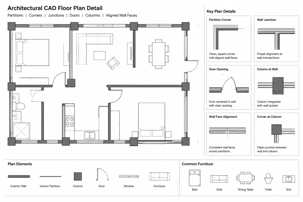
Insert openings using the project’s approved door and window symbols, but treat the block as a graphic representation rather than proof that the opening is coordinated. Check:
- Which side of the partition controls the opening location.
- Door swing and handing intent.
- Conflicts with adjacent doors, casework, fixtures, and equipment.
- Whether the wall segment can accommodate the frame and nearby finishes.
- Alignment with elevations and door schedule identifiers.
- Whether glazed openings or sidelights require a different wall condition.
Where exact opening requirements depend on a selected product, code analysis, or specialist input, flag the issue for verification rather than assuming that a generic CAD block is suitable.
Develop Wall Types Without Losing Plan Clarity
Assign wall types after the main geometry is established, but early enough to expose coordination problems. Wall construction affects the location of faces, door frames, casework, ceiling interfaces, and room dimensions.
Keep wall type tags readable and place them where the referenced wall is unmistakable. For repeated runs, avoid tagging every short segment if a clear tagging convention can communicate the same intent. Conversely, add a tag where a change in construction might otherwise be missed.
Special conditions may include shaft enclosures, wet-area partitions, acoustic separations, glazed systems, existing walls, furring, or walls with integrated millwork. Their required construction and performance must come from verified project criteria; the plan should not imply unconfirmed ratings or capabilities.
Add Dimensions in a Deliberate Hierarchy
Dimension the layout from stable references rather than chaining every room from the previous room. Long chains can accumulate changes and make it difficult to identify the controlling relationship.
A practical dimension hierarchy may include:
- Overall relationships between major building zones.
- Partitions located from grids, core walls, exterior faces, or other stable references.
- Corridor and room dimensions where clear finished space is important.
- Door and opening locations.
- Short local dimensions for recesses, returns, and offsets.
Do not dimension the same wall differently on multiple plans. If a partition is shown on an overall plan and an enlarged plan, decide which view controls the detailed layout. The other view can provide orientation and refer the reader to the controlling drawing.
Coordinate the Partition Plan with Related Views
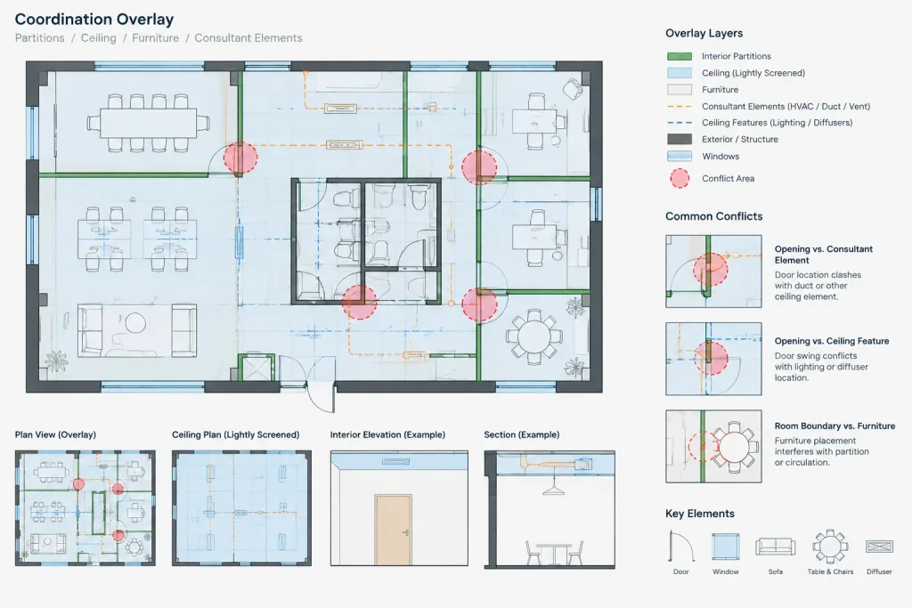
Partition changes should trigger a review of every drawing that depends on the room boundary. Useful coordination checks include:
- Reflected ceiling plans: Confirm that ceiling grids, soffits, lights, and diffusers still relate correctly to walls.
- Floor finish plans: Check finish boundaries, transitions, and room extents.
- Furniture plans: Recheck circulation, workstation placement, seating, and equipment clearances.
- Interior elevations: Verify wall lengths, openings, casework, fixtures, and elevation references.
- Door schedules: Confirm identifiers, opening types, and deleted or added doors.
- Consultant backgrounds: Issue updated backgrounds when wall changes affect devices, outlets, piping, ducts, or equipment.
Overlay reviews are especially useful after revisions. Comparing related plans visually can reveal shifted openings, old room boundaries, and ceiling or finish elements that were not updated.
Use Layers to Separate Meaning
Organize partition geometry, overhead information, door graphics, glazing, wall tags, dimensions, room information, demolition work, and reference backgrounds on appropriate layers. Layer names and properties should follow the project’s established CAD standard.
Avoid placing all plan content on a generic wall layer. Separation improves display control, plotting, consultant exports, and quality review. It also makes it easier to isolate primary partition geometry without hiding information that belongs to another drawing purpose.
Partition Plan Quality-Control Checklist
- Confirm that the plan uses the correct origin, units, and background references.
- Check major partitions against grids, columns, cores, and exterior geometry.
- Verify whether dimensions locate centerlines, construction faces, or finished faces.
- Inspect walls for inconsistent thicknesses, gaps, overlaps, and hidden fragments.
- Review every door and opening against room use and adjacent elements.
- Confirm that wall type changes are tagged clearly.
- Compare room names and boundaries with schedules and related plans.
- Check enlarged plans, elevations, ceiling plans, and finish plans after revisions.
- Remove abandoned construction lines and unused study geometry.
- Plot or preview the drawing to evaluate lineweight, annotation, and legibility.
A Coordinated Plan Is More Than Clean Linework
A strong interior partition layout plan combines accurate geometry with clear design intent. Clean wall lines are important, but they are only one part of the task. The partitions must also coordinate with openings, finishes, ceilings, furniture, structure, building services, and annotation.
By starting from controlled references, selecting consistent wall-location methods, coordinating openings early, and reviewing dependent drawings after each major change, CAD users can produce partition plans that are easier to revise and more reliable for the wider project team.
Managing Partition Revisions and Drawing Ownership
Partition changes are easier to manage when the project team knows which drawing is authoritative for each condition. An enlarged plan may control a detailed room layout, while the overall plan communicates its relationship to the surrounding floor. When both views independently dimension the same condition, conflicting information can remain unnoticed.
Use a controlled revision sequence
- Identify the approved background and the element controlling the wall location.
- Revise the primary partition geometry before editing dependent annotation.
- Recheck openings, wall type tags, room boundaries, and local dimensions.
- Review affected ceiling, finish, furniture, elevation, and service information.
- Update consultant backgrounds according to the project communication process.
- Compare the plotted result with the previous issue to find unintended changes.
Temporary studies should remain distinguishable from approved layout geometry. Construction lines, alternate room arrangements, and copied consultant information can create false authority if they are left on visible production layers.
Record unresolved coordination conditions
Not every conflict should be solved by moving a wall. A partition may be constrained by structure, equipment, an opening, a ceiling condition, or another discipline’s system. When the controlling requirement is uncertain, mark the condition for review instead of making an unsupported adjustment.
Before issuing the plan, inspect both the editable CAD geometry and the plotted presentation. This catches different classes of problems: geometry review reveals gaps and overlaps, while plot review reveals weak line hierarchy, obscured tags, clipped notes, and unreadable references.
Frequently Asked Questions
What is the difference between a floor plan and a partition layout plan?
A floor plan may communicate the overall arrangement of rooms, doors, fixtures, furniture, and other building elements. A partition layout plan places greater emphasis on the references, dimensions, wall types, openings, and geometry needed to establish interior walls. Project drawing organization determines whether this information appears together or in separate views.
Should partitions be dimensioned to the centerline or wall face?
Use the reference that clearly expresses the design and construction intent for the condition. Centerlines can support repeated or symmetrical layouts, while framing faces or finished faces may control construction or clear room geometry. The selected reference should be explicit and used consistently.
Can a generic door block confirm that an opening is coordinated?
No. A block communicates graphic intent, but it does not verify the selected product, frame condition, adjacent construction, swing conflicts, or project requirements. Check the opening against the wall assembly, schedule, room use, and verified project criteria.
Why can partition linework look correct in CAD but plot poorly?
Possible causes include inappropriate layer properties, weak lineweight hierarchy, overlapping segments, masked information, dense annotation, or reference files displaying differently than expected. Review the plotted sheet as well as the model geometry.
What should be reviewed after moving an interior wall?
Recheck connected walls, doors, room information, dimensions, wall tags, furniture, finishes, ceilings, elevations, casework, fixtures, and consultant backgrounds. The exact review depends on which drawings and systems rely on that boundary.