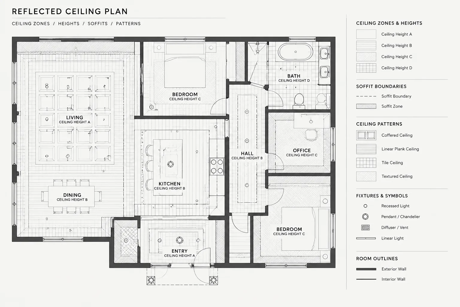
Drafting ceiling heights in architectural CAD requires more than placing elevation text on a reflected ceiling plan. Each tag must correspond to a defined ceiling zone, a clear vertical reference, and matching information in the sections, elevations, details, and room documentation.
This guide explains a practical coordination workflow for finished ceilings, soffits, sloped surfaces, and open-to-structure conditions. It also covers layer organization, tag control, xref coordination, and drawing checks that help prevent conflicting ceiling information within a DWG set.
Ceiling height information appears simple, but it often crosses several drawings and design decisions. A single room may contain a primary ceiling, a lowered soffit, an exposed structure zone, a sloped surface, or a transition between finish systems. If those conditions are shown differently in the floor plan, reflected ceiling plan, interior elevations, sections, and schedules, the drawing set becomes difficult to interpret.
A reliable CAD workflow treats ceiling height as coordinated project data rather than isolated text. The goal is to identify the controlling vertical reference, define where each ceiling condition applies, and present the information consistently at every relevant view.
Begin with a Clear Vertical Reference
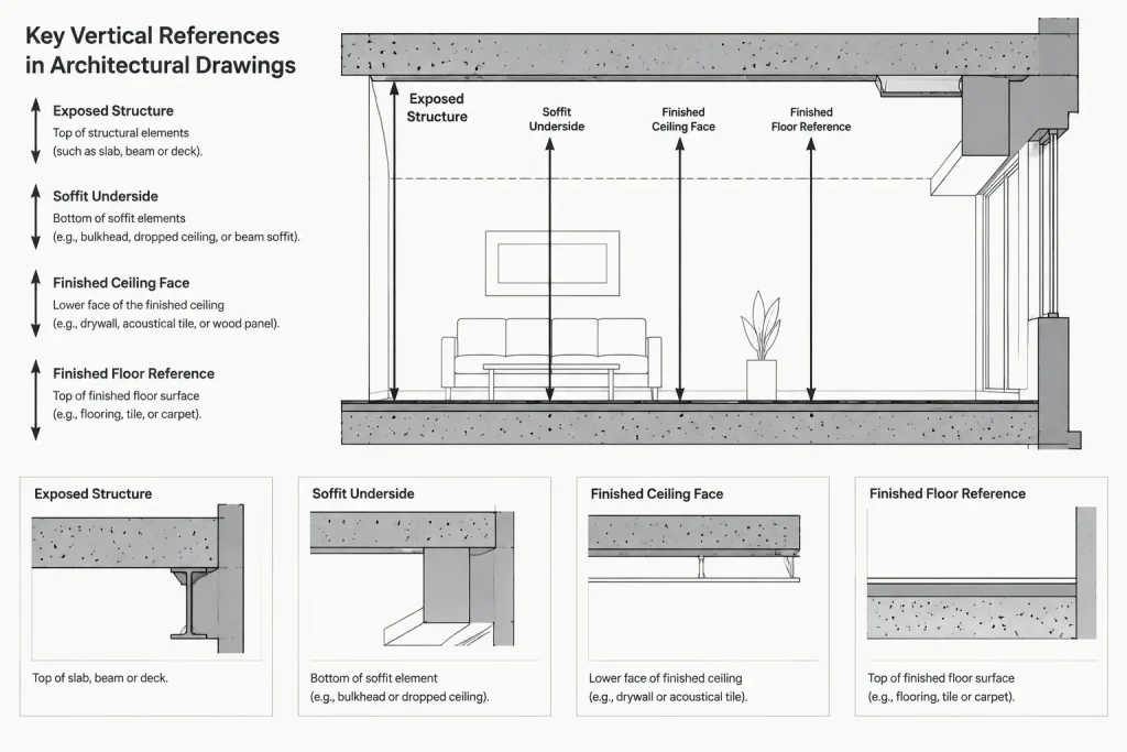
Before adding ceiling tags, confirm what the height is measured from and what surface the annotation describes. A ceiling height may be referenced from the finished floor, a project datum, or another documented elevation. The measured surface might be the face of a finished ceiling, the underside of a soffit, or the underside of exposed construction.
Do not rely on a number alone to communicate this distinction. Establish a project convention and explain it in the drawing notes or symbol legend. When unusual conditions occur, use a specific note rather than forcing them into a general convention.
The reference also needs to agree with floor elevations. If adjacent rooms have different finished floor levels, identical ceiling elevation values may not produce identical clear heights. Conversely, matching room heights may require different ceiling elevations. This distinction becomes especially important near steps, ramps, raised platforms, and floor depressions.
Separate Ceiling Geometry from Ceiling Annotation
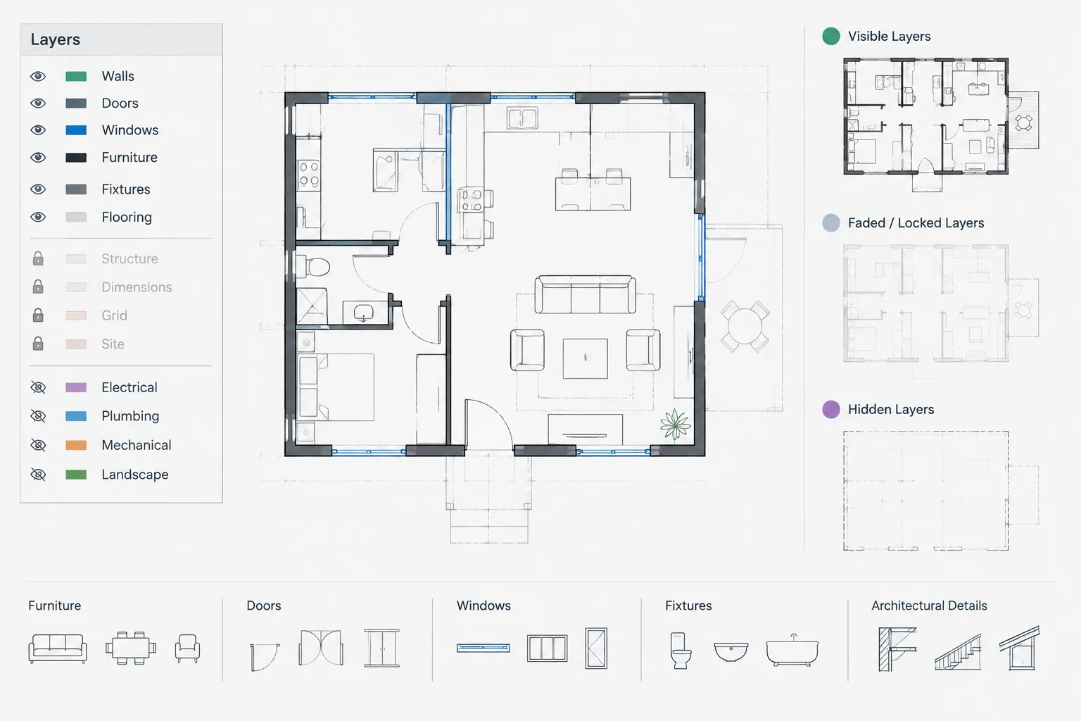
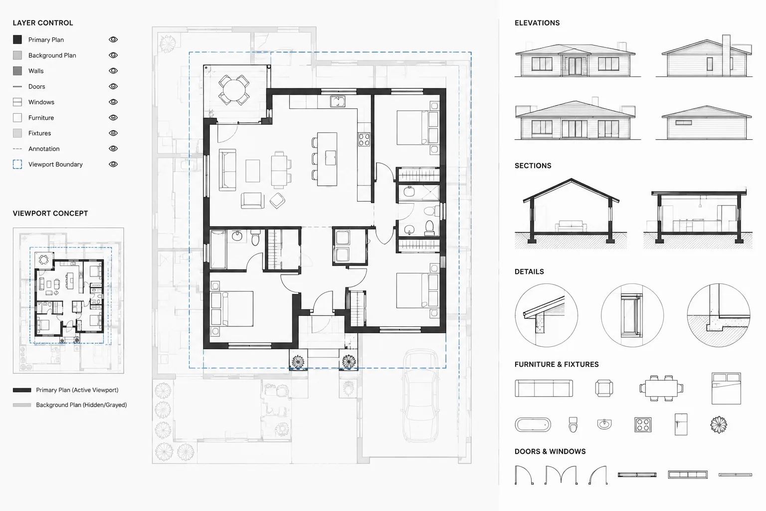
Organize the DWG so that ceiling boundaries, overhead elements, patterns, tags, and notes can be controlled independently. Exact layer names should follow the project standard, but the functional separation is more important than any particular naming format.
- Ceiling boundaries: Limits of ceiling types, height changes, soffits, and open-to-structure areas.
- Ceiling patterns: Grid systems, panel layouts, wood slats, or other repeated finish graphics.
- Overhead architectural elements: Bulkheads, beams, canopies, and objects visible in the reflected view.
- Ceiling tags and text: Height values, type references, and explanatory notes.
- Coordination backgrounds: Referenced walls, doors, casework, structural information, and consultant content.
This separation makes it easier to adjust plot hierarchy, isolate geometry during editing, and prevent a pattern or background from overpowering the height information. Keep properties ByLayer where practical so that graphic changes can be managed centrally.
Define the Extent of Every Height Condition
A ceiling tag is only useful when the reader can understand the area it governs. In a simple enclosed room, one centered tag may be sufficient. In a large open plan or a room with several ceiling levels, the extent of each condition should be made explicit.
Use ceiling edges, soffit outlines, finish boundaries, break lines, or clearly placed leaders to distinguish adjacent conditions. Avoid placing multiple height tags in an open area without visible boundaries; readers may not know where one condition ends and another begins.
Closed polylines can be useful as working geometry for ceiling zones, even when they are placed on a nonplotting coordination layer. They help designers review whether every area has been assigned a condition and can make selection, editing, and quality control more systematic. However, these boundaries should not be mistaken for actual construction joints unless that is their documented purpose.
Build a Consistent Ceiling Height Tag
A ceiling height tag should be easy to recognize and compact enough to fit within crowded reflected ceiling plans. Depending on the office workflow, it may be a standard block, an attributed block, or carefully controlled text with a symbol.
A useful tag can include:
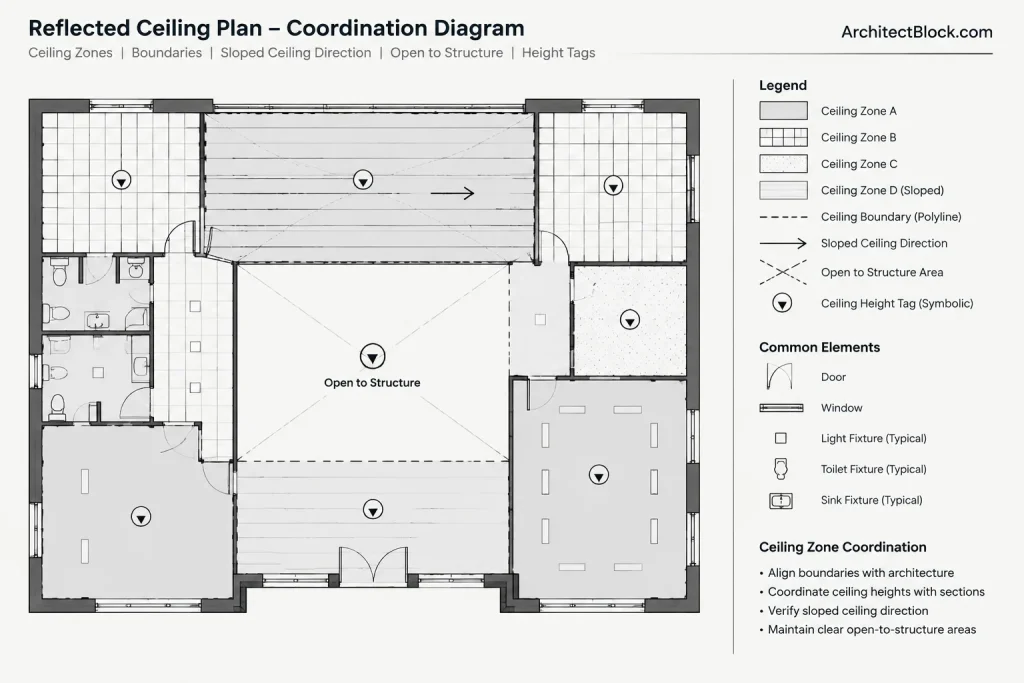
- The ceiling height or elevation.
- A ceiling type identifier when needed.
- A qualifier for sloped, exposed, or variable conditions.
- A reference to a note, detail, or interior elevation when the condition cannot be explained in plan.
Keep tag orientation consistent on the sheet. If a block is mirrored, confirm that text remains readable and that any leader or directional marker still points correctly. When attributed blocks are used, edit the attribute values rather than exploding the block into separate objects. This preserves consistent graphics and makes later checking easier.
Choose the Right Drawing for the Information
| Drawing or document | Primary ceiling-height purpose | Common coordination concern |
|---|---|---|
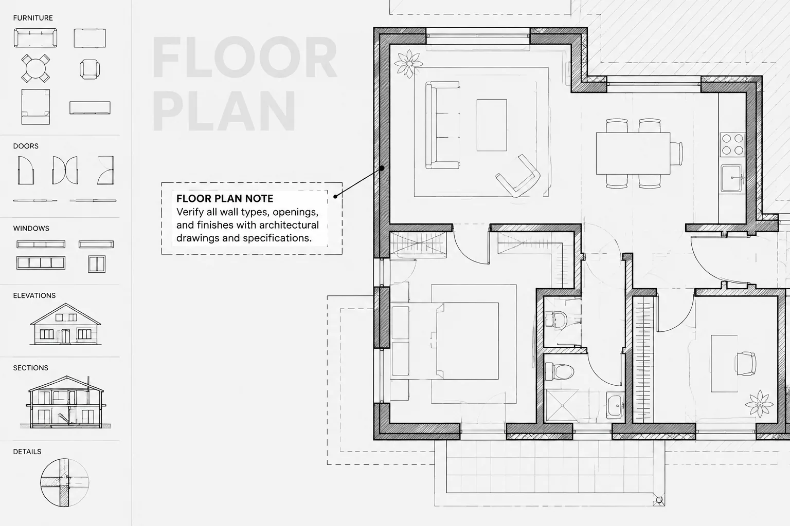
| Floor plan | Shows conditions affecting room use, clearances, or major overhead forms | Avoid duplicating every reflected ceiling plan note |
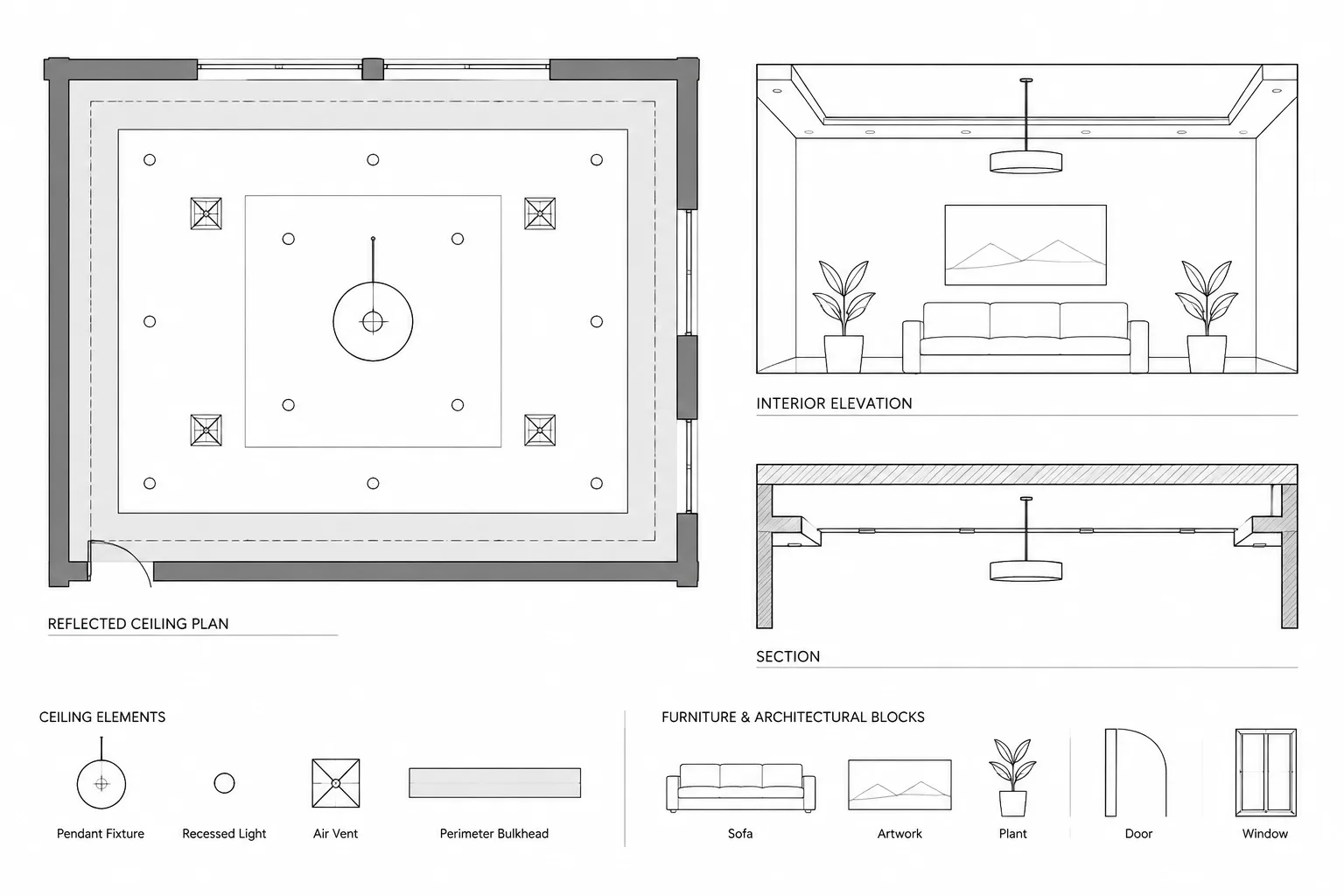
| Reflected ceiling plan | Shows ceiling zones, levels, patterns, fixtures, and overhead relationships | Make each height boundary understandable |
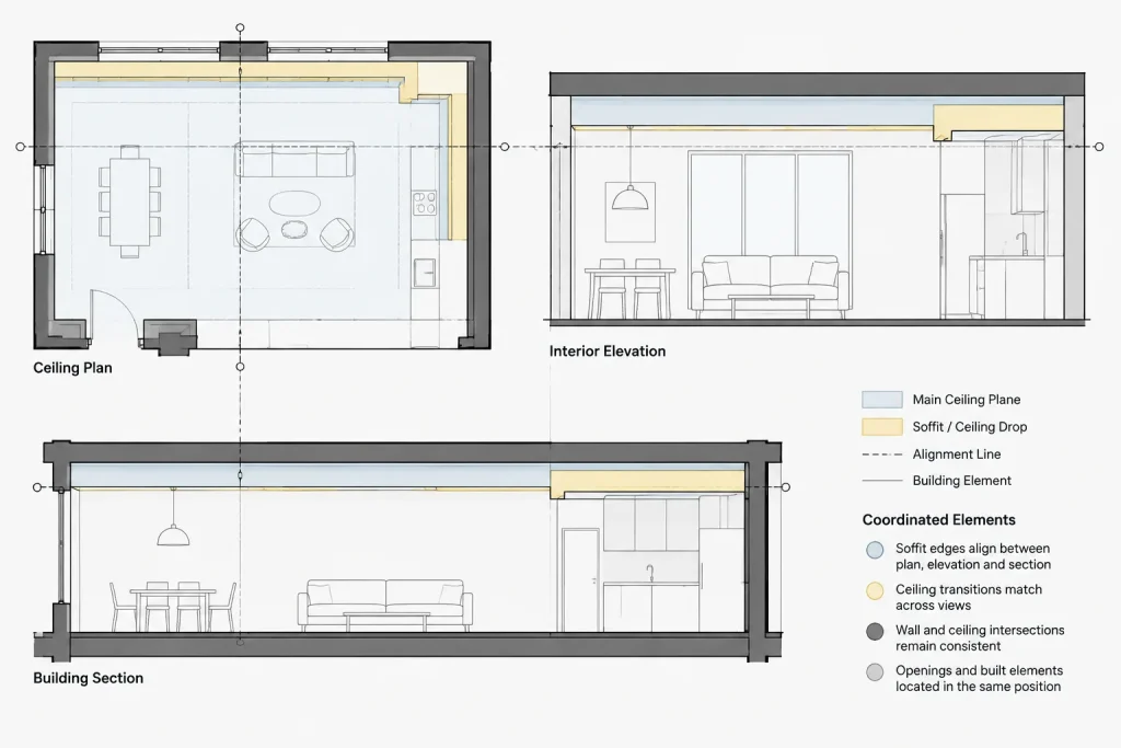
| Building section | Explains vertical relationships between floors, structure, and roof | Verify that plan tags match drawn elevations |
| Interior elevation | Shows local ceiling edges, soffits, casework relationships, and finish transitions | Coordinate horizontal lines with plan boundaries |
| Room finish information | Identifies ceiling finish or type by room | Clarify whether height is scheduled or shown elsewhere |
| Detail | Explains assemblies, edges, joints, and support relationships | Do not use the detail to contradict the controlling plan or section |
Not every drawing needs to repeat the same information. Repetition creates more locations that can become outdated. Decide which view controls the ceiling layout, then use other drawings to clarify or confirm it. A general note may direct readers to the reflected ceiling plan, but critical spatial conditions should still be visible where they affect plan interpretation.
Coordinate Soffits, Slopes, and Exposed Structure
Soffits and lowered zones
Show both the outline and the lower surface height. Where the soffit has several faces or changes depth, a section or interior elevation is usually clearer than a collection of plan notes. Coordinate the outline with walls, doors, glazing, casework, and tall equipment.
Sloped ceilings
A single tag may be misleading on a sloped surface. Indicate the direction of rise and identify controlling elevations or reference views as appropriate to the project. Sections should confirm where the slope begins, where it ends, and how it relates to roof or floor construction.
Open-to-structure areas
Do not label an exposed area as though it has a conventional finished ceiling. State what surface or element controls the indicated elevation. Structural depth, suspended services, acoustic treatments, and other overhead components may affect the usable space even when no ceiling finish is present.
Use Xrefs Without Losing Ownership of the Data
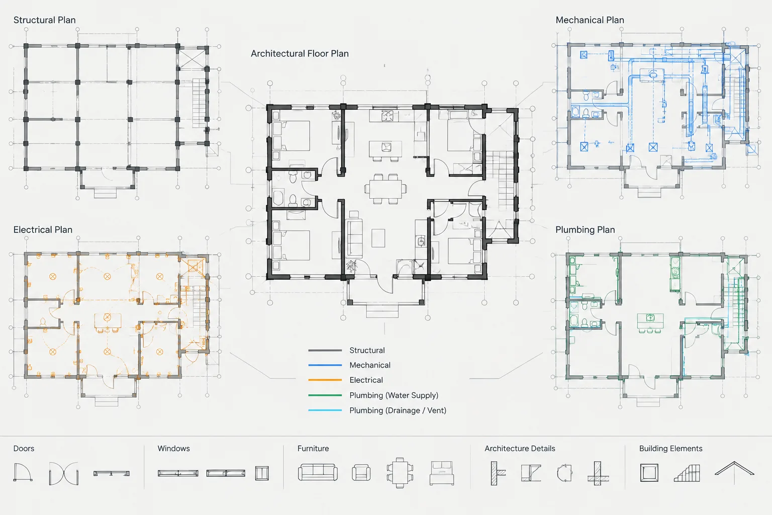
Ceiling plans commonly rely on externally referenced floor plans, structural backgrounds, and consultant files. Use these references for coordination, but decide which discipline owns each piece of published information.
Architectural ceiling boundaries and height tags should remain in the architectural file when they form part of the architectural contract documents. Consultant content can be referenced to check conflicts, but it should not be traced into the architectural file without a clear reason. Traced geometry quickly becomes stale when the source changes.
Keep xrefs aligned to the agreed project origin and avoid casually moving a background to make one view appear correct. If alignment is wrong, diagnose the coordinate or reference-path issue rather than creating a local offset that hides the problem.
Run a Ceiling Height Coordination Check
A focused review is more effective than visually scanning the sheet at random. Isolate the relevant layers and work through the plan room by room or zone by zone.
- Confirm that each enclosed room or open zone has an identifiable ceiling condition.
- Check that every height change has a visible boundary or an unambiguous leader.
- Compare ceiling tags with building sections and interior elevations.
- Review floor elevation changes that alter clear height.
- Check doors, glazing, tall casework, partitions, and equipment against lowered ceilings.
- Confirm that tags do not cover fixtures, grids, dimensions, or room identifiers.
- Look for copied tags that retained values from another area.
- Verify that sloped and exposed conditions use appropriate qualifiers.
- Inspect viewport layer settings so required tags and boundaries appear on plotted sheets.
- Plot or preview the sheet to evaluate lineweight, text size, and background contrast.
Where drawings disagree, do not resolve the issue by changing only the most visible label. Identify the intended design condition first, then update every affected view and schedule. Marking the corrected locations during review helps ensure that the change has propagated through the set.
Keep the Workflow Maintainable
The most dependable ceiling-height drawings use a limited family of symbols, a clear layer structure, and a defined source of truth. Reuse approved tag blocks, but verify their values after copying. Keep working boundaries separate from plotted construction lines. Use sections and elevations for complex vertical conditions instead of overloading the plan with text.
Finally, treat ceiling heights as part of a broader coordination system. They interact with floor levels, structure, lighting, mechanical services, partitions, doors, windows, finishes, and built-in components. Project-specific requirements, applicable codes, and manufacturer information must be checked separately. A clean DWG improves communication, but it does not replace technical verification.
Turning Ceiling Information into Coordinated Drawing Data
The strongest workflow distinguishes between design intent, drawn geometry, and published annotation. Design intent establishes the required spatial condition. Geometry shows where that condition begins and ends. Annotation identifies the condition for the reader. Treating these as related but separately controlled elements makes changes easier to trace.
When a ceiling revision occurs, begin with the controlling design condition rather than editing the nearest tag. Review the affected boundary, floor reference, adjoining construction, section cuts, interior elevations, finish information, and consultant backgrounds. This prevents a graphic correction from leaving contradictory information elsewhere in the set.
Prepare Ceiling Drawings for Review and Handoff
A ceiling plan should remain understandable when opened by another CAD user or reviewed without access to informal project knowledge. Before issuing or sharing the file, confirm that layer states, referenced backgrounds, annotation symbols, and plotted line hierarchy communicate the intended relationships.
- Check ownership: Keep architectural ceiling information in the file responsible for publishing it.
- Check references: Confirm that tags describe the intended finished surface, soffit face, or exposed construction condition.
- Check extents: Make each ceiling zone readable without depending on tag proximity alone.
- Check related views: Review the plan beside relevant sections and elevations rather than checking each sheet in isolation.
- Check revisions: Search for copied symbols, obsolete notes, hidden boundaries, and viewport-specific layer overrides.
- Check output: Evaluate a plotted or previewed sheet because readable model-space graphics may not remain clear at publication scale.
This process supports clearer architectural communication, but it does not establish code compliance or verify the performance of ceiling assemblies. Project requirements, consultant designs, manufacturer information, and applicable regulations still require separate professional review.
Frequently Asked Questions
Where should ceiling heights be shown in an architectural drawing set?
The reflected ceiling plan commonly communicates ceiling zones and height changes, while sections and interior elevations explain vertical relationships. Floor plans, finish information, and details may include related information when it affects interpretation, but unnecessary repetition should be avoided.
Should a ceiling height be measured from the finished floor?
That depends on the project convention. The annotation must make clear which datum or floor condition controls the measurement and which overhead surface it describes. Adjacent floor elevation changes should be reviewed because they can change the resulting clear height.
How should several ceiling heights within the same room be drafted?
Show visible boundaries between conditions and place each tag so its area of application is unambiguous. Soffit outlines, finish limits, break lines, leaders, sections, or interior elevations can clarify conditions that cannot be communicated reliably by tag placement alone.
How should a sloped ceiling be annotated?
Identify the sloped condition, communicate the direction of rise, and reference the view that defines its vertical geometry. Avoid using a single unlabeled height that could be mistaken for a constant horizontal ceiling.
How should open-to-structure space be represented?
Describe the actual overhead reference rather than presenting the area as a conventional finished ceiling. The drawing should distinguish exposed construction from suspended or applied finish systems and coordinate other overhead components that affect the space.
Why do ceiling tags become inconsistent after copying?
Copied symbols can retain values, qualifiers, or references from their original locations. Keep reusable tags intact, edit their controlled values, and include copied annotations in the drawing review rather than assuming their placement makes them correct.
Can consultant xrefs replace architectural ceiling information?
Consultant xrefs can support coordination, but published architectural ceiling boundaries and annotations should remain under clear architectural ownership when they are part of the architectural documents. Avoid tracing referenced content merely to duplicate information.