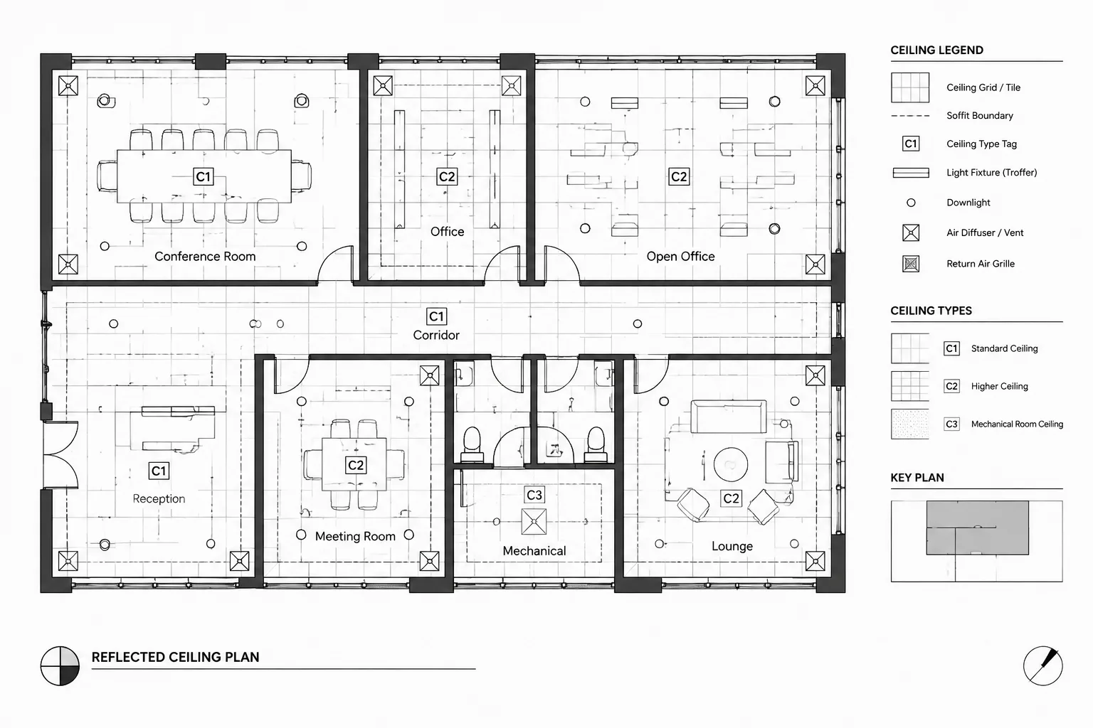
A successful ceiling grid layout in architectural CAD depends on more than repeating a module across a room. The drafter must establish where the system begins and ends, select a rational origin, preserve the pattern through irregular conditions, and coordinate the grid with architectural and consultant information.
The guidance below presents a practical reflected ceiling plan workflow. Use it to make layout decisions visible, keep revisions manageable, and identify conflicts without assuming responsibility for another discipline’s design.
A ceiling grid may look repetitive, but it is rarely a simple field of evenly spaced lines. The layout must respond to room geometry, ceiling types, lighting, air devices, sprinklers, access panels, partitions, soffits, and other overhead elements. A poorly controlled grid can create narrow perimeter pieces, misaligned fixtures, or conflicts that remain hidden until late coordination.
This guide explains how to develop a ceiling grid layout in CAD as a coordinated architectural system rather than decorative linework. It focuses on drawing structure, placement decisions, fixture relationships, edge conditions, and quality control. Actual tile modules, suspension requirements, clearances, and installation constraints must be verified against the selected ceiling system, consultant information, project criteria, and applicable requirements.
Start With a Reliable Reflected Ceiling Plan Base
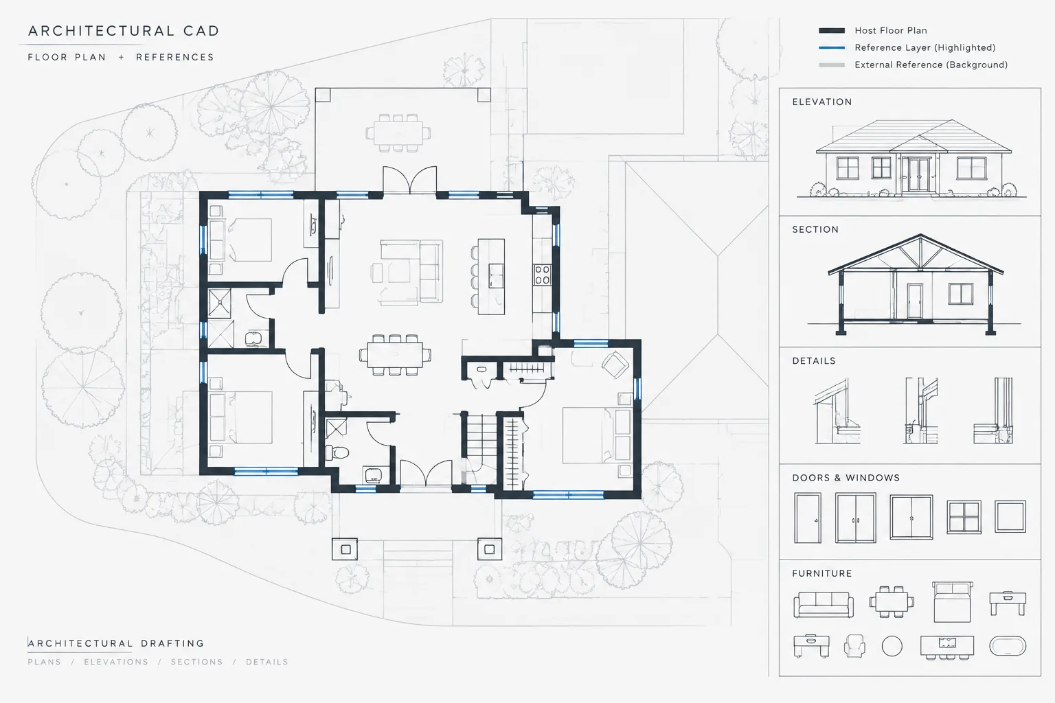
Build the ceiling layout over a current architectural background. The base should clearly identify room boundaries, partition faces, columns, shafts, openings, soffits, ceiling transitions, and other elements that affect the visible ceiling area.
Use an external reference or another controlled background method when the floor plan is maintained in a separate file. Avoid redrawing walls solely for the reflected ceiling plan. Duplicate geometry can drift out of coordination when the plan changes.
Before laying out a grid, confirm:
- The architectural background is current and correctly positioned.
- Room boundaries match the intended finished wall faces.
- Ceiling types and height changes are identified.
- Bulkheads, soffits, coves, clouds, and open-to-structure areas are shown.
- Available consultant backgrounds use the same project origin and orientation.
- Rooms requiring enlarged ceiling plans are known.
Separate Ceiling Systems From Ceiling Annotation
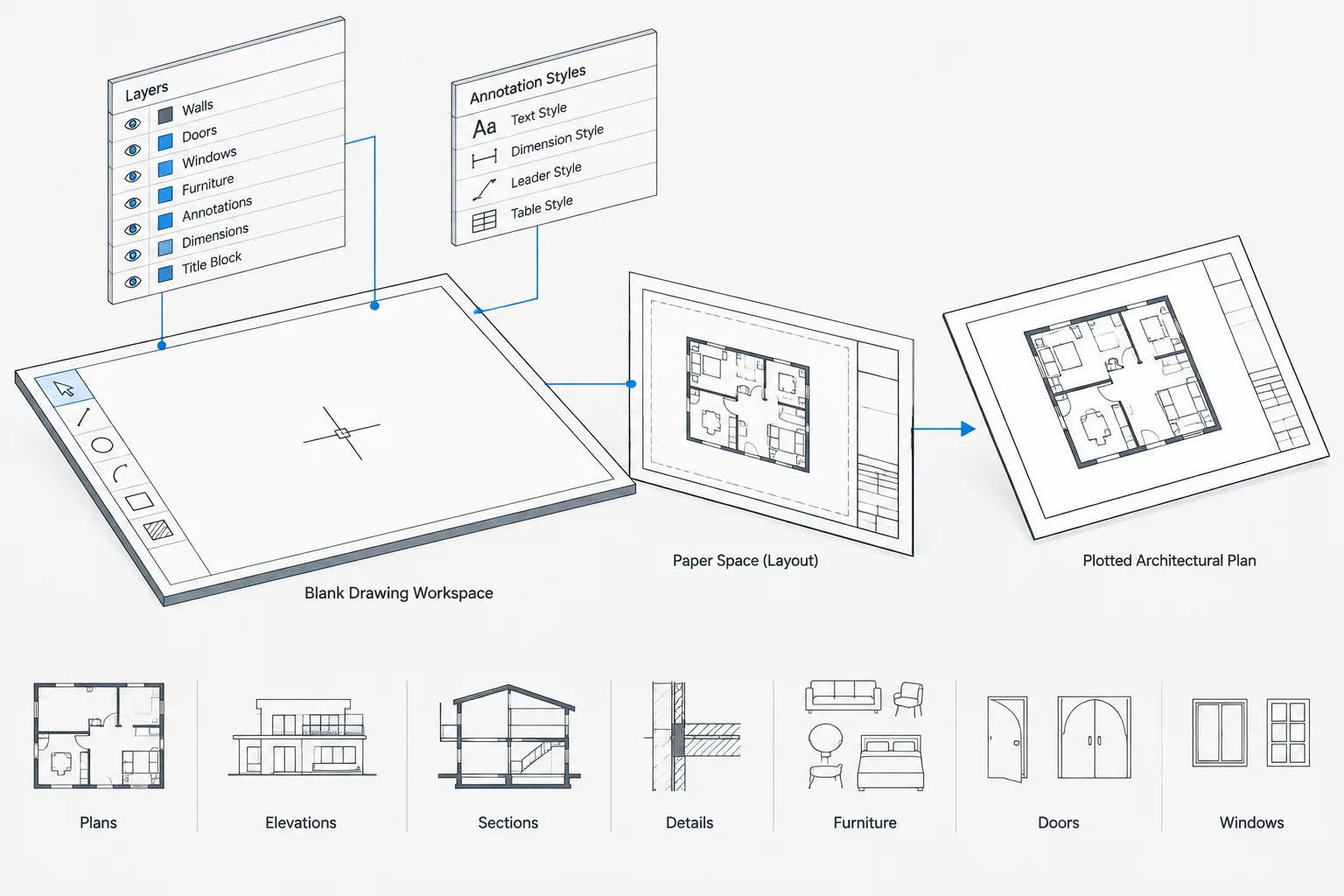
A clear layer structure makes the reflected ceiling plan easier to edit and review. Keep grid geometry separate from tags, notes, fixtures, and background information. This allows each category to receive an appropriate lineweight and lets users isolate the grid during coordination.
| Drawing content | Recommended control | Reason |
|---|---|---|
| Primary ceiling grid | Dedicated ceiling-grid layer | Allows global graphic and visibility control |
| Special grid or secondary pattern | Separate layer when useful | Distinguishes different systems or orientations |
| Ceiling boundaries and transitions | Dedicated boundary layer | Clarifies where systems begin and end |
| Ceiling fixtures and devices | Category-based layers | Supports coordination and selective display |
| Ceiling tags and notes | Annotation layers | Keeps descriptive information independent of geometry |
| Consultant backgrounds | Xref-dependent or controlled background layers | Preserves source ownership and graphic hierarchy |
Exact layer names should follow the office or project CAD standard. The important principle is to avoid placing the grid, fixtures, notes, and architectural background on one layer.
Define the Ceiling Boundary Before Drawing the Grid
Establish the true visible boundary of each gridded ceiling area. In a simple room, that boundary may follow finished partition faces. In more complex spaces, it may be interrupted by soffits, perimeter coves, columns, ceiling clouds, angled walls, or transitions to another ceiling material.
A closed polyline can be useful as a temporary control object for checking the layout extent. It can also support hatching or area review when appropriate. Keep temporary construction geometry on a nonplotting layer so it does not appear on issued sheets.
Do not assume that every wall line defines the ceiling edge. Review details and sections to determine whether the grid terminates at the wall, continues over a partial-height partition, stops at a bulkhead, or changes at an opening.
Choose a Defensible Grid Origin
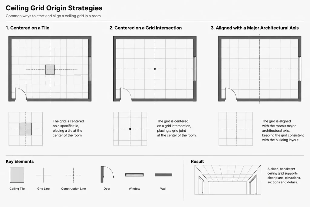
The grid origin controls the appearance of every perimeter cut and the alignment of ceiling-mounted elements. Choose it deliberately rather than starting from an arbitrary coordinate.
Common layout approaches
- Centered in the room: Useful where balanced perimeter conditions are visually important.
- Aligned with a major architectural axis: Appropriate where corridors, structural bays, storefronts, or feature walls establish a strong organizing line.
- Aligned through connected spaces: Useful when visual continuity is intended across openings or between related rooms.
- Coordinated with fixture rows: Appropriate when the design establishes a strong relationship between the grid, lighting, and other ceiling devices.
- Established from a controlled reference: Sometimes required where construction layout must relate to a documented datum or known architectural feature.
Centering does not always mean placing a grid intersection at the room center. Depending on the module and design intent, a tile centerline, main runner, or joint may align with the center. Test more than one option before committing to the layout.
Build the Grid With Editable Geometry
Use a method that remains easy to revise. Common approaches include offset construction lines, rectangular arrays, repeated blocks, or linework generated from a controlled module. The best choice depends on office practice and the complexity of the ceiling.
A practical manual workflow is:
- Draw reference axes through the selected grid origin.
- Create the first grid lines in each direction.
- Repeat the lines using the verified ceiling module.
- Extend the pattern beyond the ceiling boundary.
- Trim or clip the visible grid to the correct ceiling area.
- Remove or hide construction geometry after checking the result.
Avoid exploding intelligent or grouped content without a clear reason. Excessive fragmented linework makes future shifts more difficult and increases the chance that part of the grid will be left behind.
Evaluate Perimeter Conditions, Not Just the Center
After generating the grid, inspect every edge. A mathematically centered pattern may still create awkward pieces where the room is irregular, a column interrupts the field, or a soffit changes the boundary.
Review the following conditions:
- Opposite perimeter cuts and their visual balance
- Narrow or fragmented pieces along walls and soffits
- Grid intersections near columns or wall offsets
- Transitions between different grid directions
- Edges around ceiling clouds and framed openings
- Changes where corridors meet larger rooms
- Alignment through doors, glazed openings, or open connections
If the layout is unsatisfactory, shift the whole grid from its controlled origin. Do not repair individual edges by moving isolated lines, because that breaks the module and creates an internally inconsistent pattern.
Coordinate Fixtures and Devices by Category
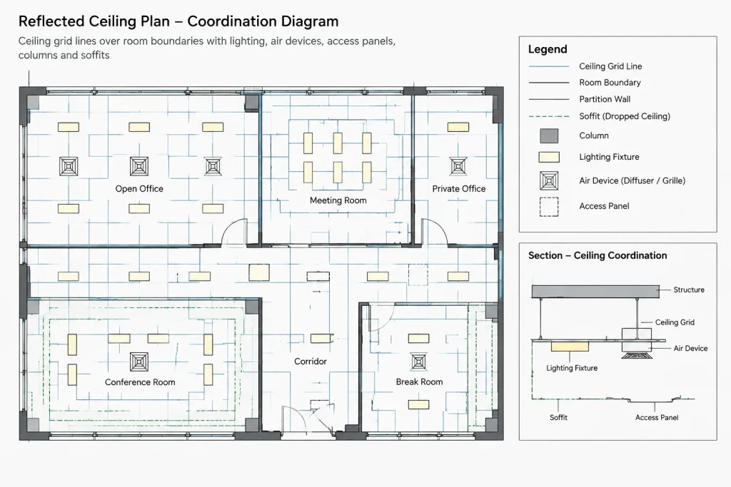
Once the base grid is stable, overlay the current lighting and engineering information. Ceiling devices may include luminaires, air terminals, sprinkler components, speakers, detectors, sensors, cameras, access panels, and specialty equipment. Their final placement and technical requirements remain the responsibility of the appropriate design discipline.
Organize coordination in passes rather than trying to resolve everything at once:
- Major architectural elements: Check soffits, ceiling transitions, folding partitions, overhead doors, and tall casework.
- Lighting: Review whether fixtures are centered in tiles, aligned with grid lines, or intentionally independent of the grid.
- Mechanical devices: Check supply, return, and other air devices against fixtures and ceiling boundaries.
- Fire protection and life-safety devices: Display consultant locations for coordination without independently changing required coverage or placement.
- Special systems: Review speakers, sensors, cameras, projectors, access panels, and owner equipment.
Use distinct blocks and layers for different device categories. Avoid substituting generic symbols when the distinction affects coordination. If a symbol is diagrammatic, make that limitation clear through the drawing conventions or notes.
Use Consistent Placement Rules
A reflected ceiling plan becomes easier to review when similar elements follow consistent placement logic. For example, a project may generally center certain devices within ceiling panels while aligning others with grid intersections or architectural axes. Exceptions should be intentional and documented.
Do not force every device into the same visual rule. Some elements are constrained by performance, coverage, access, structure, or routing. Architectural alignment is only one part of coordination. When a conflict appears, flag it for the responsible discipline rather than moving consultant content without confirmation.
Handle Irregular and Curved Rooms Carefully
Angled walls, curved boundaries, and nonorthogonal spaces often require judgment. A rectangular grid may remain aligned with the primary building geometry even where the room perimeter changes direction. Alternatively, a separate grid orientation may be part of the design.
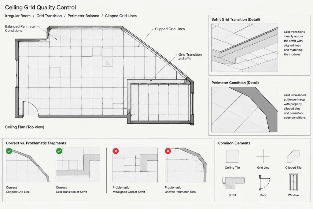
Clearly show where one orientation stops and another begins. Avoid overlapping full grid patterns, which can produce ambiguous fragments at transition zones. A ceiling boundary, trim condition, bulkhead, or another documented transition should explain the change.
For curved edges, represent the actual ceiling termination rather than approximating it with a sequence of unrelated straight cuts. Enlarged plans or details may be needed when the floor-plan scale cannot communicate the edge condition clearly.
Coordinate Plans With Sections and Details
The reflected ceiling plan shows horizontal organization, but it cannot explain every vertical relationship. Check the grid against building sections, interior elevations, wall sections, and ceiling details.
Verify that these drawings agree on:
- Ceiling height and changes in level
- Soffit width, depth, and extent
- Perimeter trim or reveal conditions
- Transitions between ceiling materials
- Openings, access zones, and ceiling clouds
- Relationships to full-height and partial-height partitions
- Feature lighting and recessed elements
If a plan boundary cannot be understood without a section, add or coordinate an appropriate reference. Do not overload the reflected ceiling plan with detail-level linework that becomes illegible at the sheet scale.
Perform a Focused Quality-Control Review
Review the ceiling grid with unnecessary layers hidden. Then repeat the review with all ceiling devices and relevant backgrounds visible.
- Confirm each gridded area has a deliberate origin and orientation.
- Check that the grid does not pass through soffits, shafts, columns, or non-gridded ceiling areas.
- Look for isolated line fragments and duplicate grid lines.
- Check perimeter pieces throughout the room, not only at two opposite walls.
- Verify fixture and device alignment against the current grid.
- Confirm ceiling type and height tags point to the correct regions.
- Compare transitions with sections and interior elevations.
- Check that consultant backgrounds are current and correctly aligned.
- Plot or preview the sheet to evaluate lineweight, density, and legibility.
A clean ceiling grid layout in CAD is the result of controlled geometry and interdisciplinary review. Establish the boundary, choose a rational origin, maintain an unbroken module, and coordinate devices without overriding the responsible consultant’s design. That workflow produces a reflected ceiling plan that is easier to revise, check, and interpret during documentation and construction.
Document the Reason Behind the Layout
A ceiling grid can be shifted easily in CAD, but the reasoning behind its position may not be obvious to the next person editing the drawing. Record the controlling alignment when it affects multiple rooms, fixture rows, architectural axes, or important transitions. This can be communicated through construction geometry, an internal coordination note, or another office-approved method that does not clutter the issued plan.
When reviewing a revision, determine whether the original control still applies before moving the grid. A changed partition, soffit, or ceiling boundary may alter perimeter conditions without invalidating the intended alignment elsewhere.
Distinguish Design Decisions From Coordination Flags
Not every visible conflict should be solved directly in the architectural file. Separate issues the architectural team can resolve from items requiring confirmation by lighting, mechanical, fire protection, structural, or specialty consultants.
- Architectural decisions: Grid orientation, visible boundaries, ceiling transitions, and relationships to architectural axes.
- Coordination questions: Devices that overlap, fall across transitions, or appear inconsistent with the current ceiling geometry.
- Consultant-controlled decisions: Technical placement, performance, coverage, support, routing, and access requirements assigned to another discipline.
Keep flagged conditions traceable until they are resolved. Once updated information is received, replace temporary markups with coordinated geometry and confirm that the change has not introduced a new conflict elsewhere.
Review the Drawing as a Communication Tool
Final review should consider how the reflected ceiling plan will be interpreted, not only whether the CAD geometry is technically clean. Grid lines should remain subordinate to important boundaries, fixtures, tags, and change-of-level information. Closely spaced or overlapping symbols may require an enlarged view rather than additional linework in the main plan.
The strongest drawing clearly differentiates ceiling systems, explains transitions, and lets reviewers identify device relationships without tracing through unrelated backgrounds. That clarity is essential when the same layout is used for design review, consultant coordination, documentation, and field interpretation.
Ceiling Grid Layout FAQ
Should a ceiling grid always be centered in the room?
No. Centering is one possible approach, but a major architectural axis, connected-space alignment, feature wall, corridor, or coordinated fixture arrangement may provide a more defensible origin. Review perimeter conditions before selecting the final position.
Why should the grid be kept separate from fixtures and notes?
Separate layers allow the grid, device categories, boundaries, and annotation to be isolated and displayed with an appropriate graphic hierarchy. This also makes revisions and conflict reviews easier.
Can consultant devices be moved to improve visual alignment?
Potential adjustments can be identified and discussed, but consultant-controlled devices should not be relocated without confirmation from the responsible discipline. Their positions may depend on performance, coverage, routing, access, or other technical constraints.
How should an irregular room be handled?
First identify the intended ceiling orientation and actual visible boundary. Maintain a consistent module within the defined field, then evaluate cuts at angled walls, curves, columns, soffits, and transitions. Avoid shifting isolated grid lines to repair individual edges.
What should be checked after the architectural plan changes?
Reload or update the controlled background, then review ceiling boundaries, origins, perimeter conditions, soffits, partitions, fixture relationships, tags, and references to sections or details. Confirm that consultant backgrounds still share the correct origin and orientation.
When is an enlarged ceiling plan useful?
An enlarged plan is useful when transitions, curved edges, concentrated devices, or closely spaced annotations cannot be communicated clearly at the main reflected ceiling plan scale.