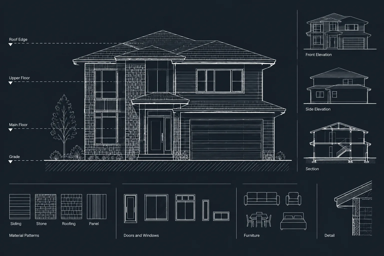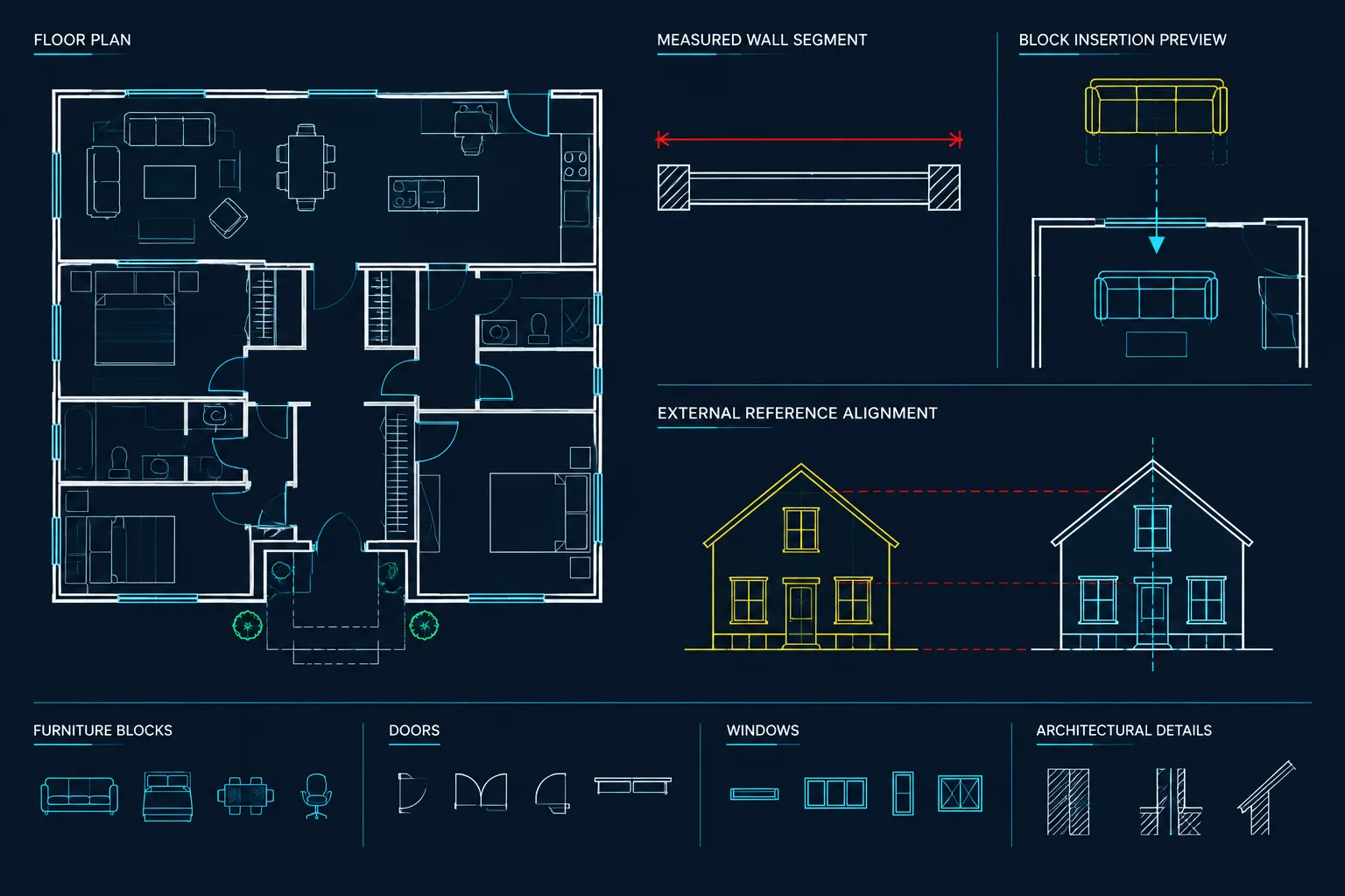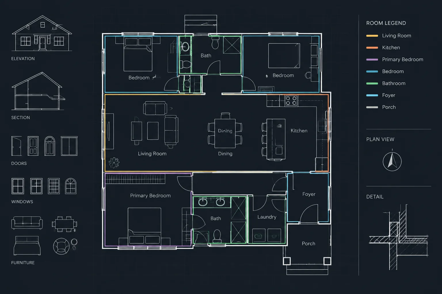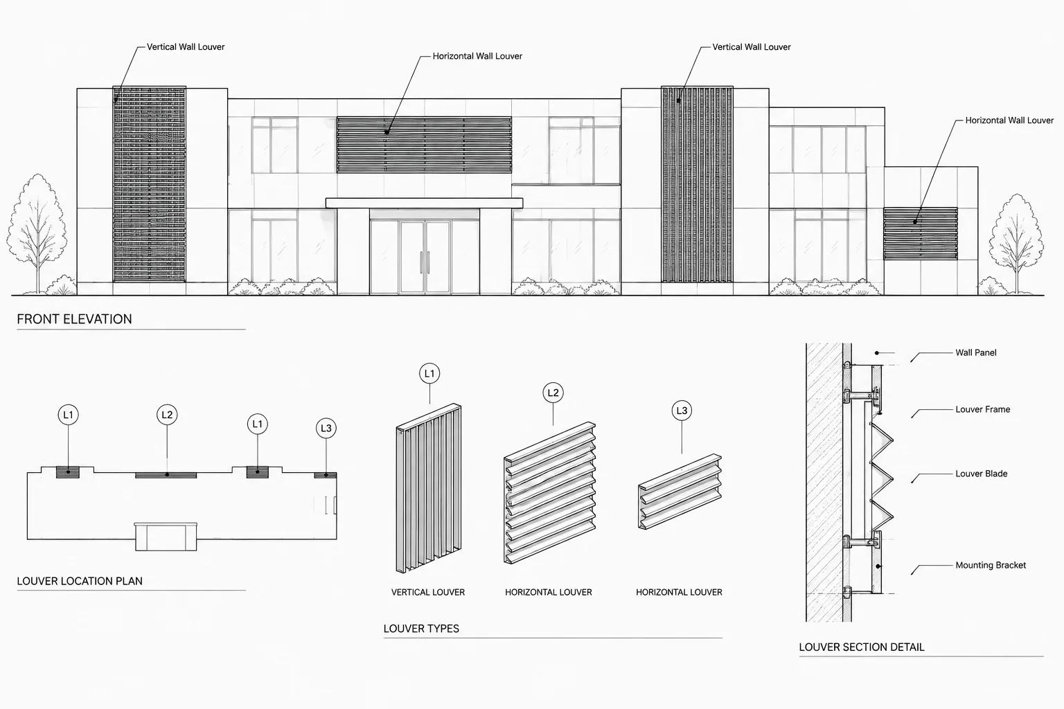
Architectural louver CAD coordination involves more than placing a blade-pattern symbol on an exterior elevation. The opening must remain consistent across plans, elevations, sections, details, schedules, consultant backgrounds, and enclosure documentation.
This guide explains how to build a clear architectural representation while keeping product performance and discipline-specific requirements tied to verified project information. The emphasis is on drawing clarity, controlled CAD content, and a review process that exposes conflicts before the louver is treated as a resolved construction condition.
Architectural louvers often appear simple in elevation, but each one can affect the wall opening, exterior appearance, mechanical system, structure, flashing, and interior construction. A rectangle filled with parallel lines may communicate the design concept, yet it does not provide enough information for coordinated construction drawings.
A reliable architectural louver CAD coordination workflow connects every louver shown in plan or elevation to its opening, identification tag, schedule data, details, and consultant requirements. The architect should also distinguish confirmed information from placeholders. Airflow performance, pressure drop, water resistance, screening, finish, and other product characteristics must come from the project specifications, consultants, and selected manufacturer rather than assumptions embedded in a generic CAD block.
Define the Louver Before Drafting It
Begin by identifying why the louver is present and which discipline controls its functional requirements. Common applications include outside-air intake, exhaust discharge, equipment ventilation, wall-cavity ventilation, and architectural screening. These uses may look similar on an elevation but require different coordination.
Collect the available information before developing the architectural representation:
- Approximate opening location and size
- Wall type and exterior cladding assembly
- Room or equipment served
- Required duct connection or plenum arrangement
- Structural framing around the opening
- Exterior and interior finish expectations
- Sill, head, jamb, flashing, and drainage conditions
- Access requirements for cleaning or replacement
- Tagging and scheduling conventions used by the project
If a mechanical engineer establishes the free-area or airflow requirement, the architect should not replace that requirement with a nominal opening selected only for visual alignment. Likewise, a desired elevation module should be reviewed against the functional opening rather than imposed without consultation.
Represent Louvers According to Drawing Purpose
A single louver may appear differently in a floor plan, exterior elevation, wall section, enlarged plan, and detail. Each view should communicate the information appropriate to its scale and purpose instead of repeating the same block everywhere.
Floor Plans
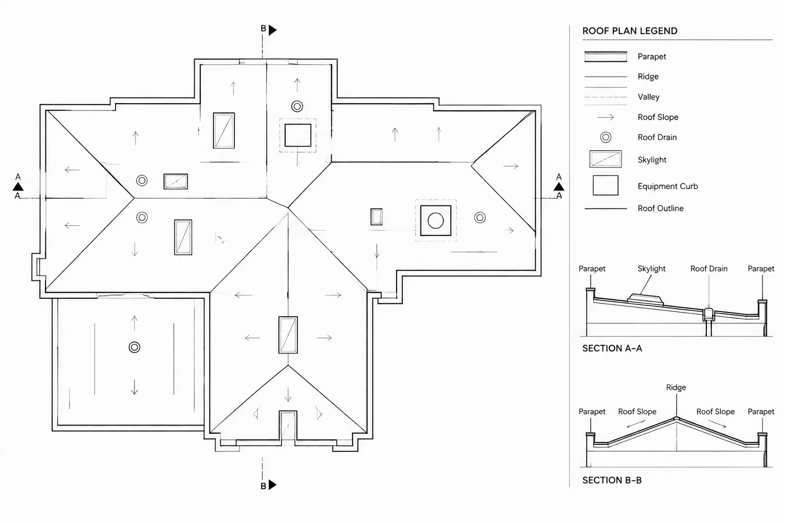
In plan, show the wall opening and the louver’s relationship to the wall assembly. At smaller drawing scales, a simplified line or narrow rectangular symbol may be sufficient. Enlarged plans may need to show frame depth, duct or plenum alignment, adjacent finishes, and nearby obstructions.
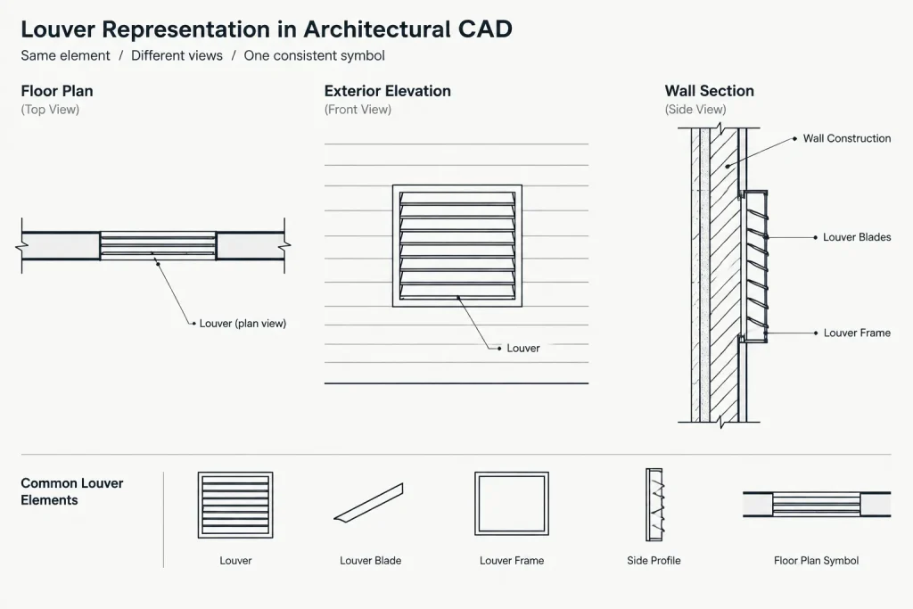
Avoid drawing louver blades in plan unless they clarify a meaningful condition. Dense blade graphics can make the wall difficult to read and may imply a product configuration that has not been selected.
Exterior Elevations
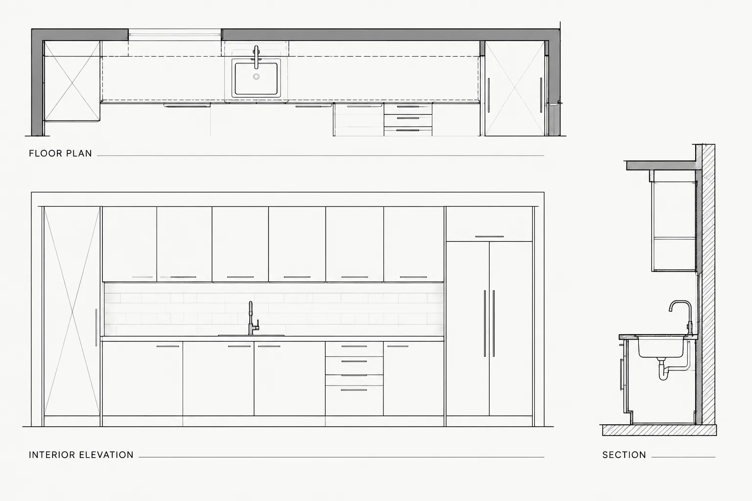
The elevation usually carries the clearest architectural representation. Show the visible frame, overall opening, and a restrained blade pattern. Use lineweight and spacing that remain legible at the plotted scale. The pattern should communicate a louver without becoming a dark graphic patch.
Coordinate the edges with masonry modules, panel joints, window heads, parapets, architectural bands, and other façade datums. If the design calls for several louvers to read as a group, verify that the proposed alignment remains compatible with duct routing and structural framing.
Sections and Details
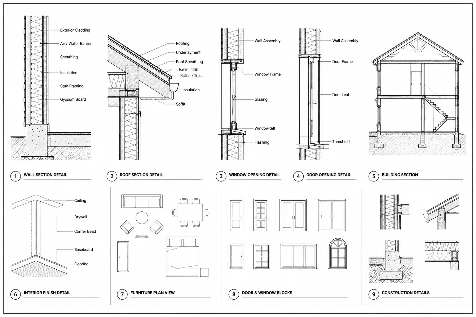
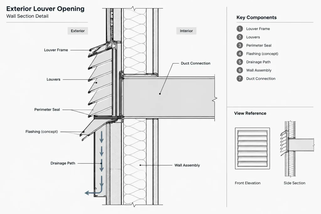
A wall section should explain how the louver relates to the complete enclosure. Depending on the project stage, this may include the opening frame, perimeter seal, flashing concept, sill drainage path, interior liner, duct or plenum connection, insulation transitions, and nearby air or water control layers.
Generic details should not imply unverified attachment methods or proprietary profiles. Use them to establish design intent, then reconcile them with structural requirements, project specifications, and manufacturer information.
Use a Controlled CAD Block
A reusable louver block can improve consistency, but it should remain simple and editable. Build the block around the information the team repeatedly needs rather than attempting to model every blade.
A practical elevation block may contain:
- An outer frame boundary
- A simplified blade pattern
- A clear insertion point
- Geometry that can be adjusted without distorting line spacing
- An optional tag or attribute that follows office standards
- Separate components for visible outlines and internal pattern graphics
Choose an insertion point that supports coordination. A corner may help align the opening with façade datums, while a center point may help with symmetrical placement. Whichever method is selected, use it consistently and document it in the block library.
Do not store project-specific performance values inside an otherwise generic symbol. If attributes are used, limit them to controlled identifiers such as a louver mark or reference note. Detailed performance data belongs in verified schedules, specifications, or consultant documents.
Coordinate the Opening, Not Just the Symbol
The louver graphic and the constructed wall opening are related but not necessarily identical. Frames, sleeves, perimeter joints, and installation tolerances can affect the required rough opening. Generic CAD content should therefore be treated as a coordination aid rather than a source of final opening dimensions.
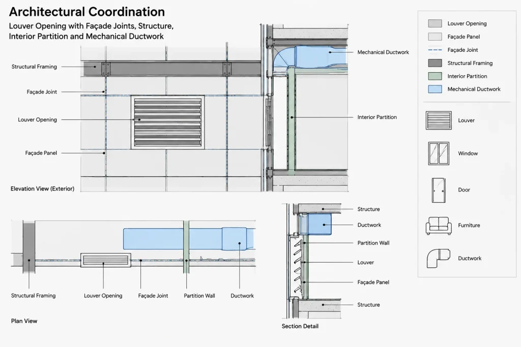
Check the louver against each surrounding system:
| Coordination area | Questions to review |
|---|---|
| Architecture | Does the louver align with façade joints, finish transitions, interior partitions, and visible room elements? |
| Mechanical | Does the opening serve the intended duct, plenum, or equipment, and is the connection route workable? |
| Structure | Does the opening conflict with columns, beams, braces, lintels, reinforcing, or other framing? |
| Building enclosure | Are flashing, drainage, perimeter seals, and control-layer transitions shown or referenced? |
| Electrical and controls | Are actuators, sensors, dampers, or nearby services coordinated where applicable? |
| Maintenance | Can screens, filters, dampers, or adjacent equipment be reached if the design requires access? |
Compare the architectural plan and elevation with the mechanical drawings. A louver can appear centered and orderly on the façade while its associated duct is offset, blocked, or connected to a different location in the consultant background.
Tag and Schedule Louvers Consistently
Projects with multiple louver types benefit from a controlled identification system. The tag should point to information that is maintained in one reliable location, such as a louver schedule, opening schedule, exterior elevation legend, or keyed note system.
A louver schedule may organize information such as:
- Unique mark
- Location or associated room
- Nominal opening information
- Service or function
- Frame or finish description
- Screen, damper, or accessory references where applicable
- Detail and specification references
- Coordination remarks
Schedule fields should reflect the project’s actual documentation strategy. Avoid copying unverified values from a manufacturer drawing or an earlier project. When information remains unresolved, identify it as pending coordination rather than filling the field with an assumed selection.
Place louver tags where they do not resemble window marks, door numbers, or mechanical equipment tags. If the same louver is shown on several views, confirm that every tag points to the same record.
Manage Layers and Graphic Hierarchy
Keep louver geometry separate from wall, glazing, mechanical, and annotation content. The exact layer names should follow the project standard, but the organization should allow users to control the outer frame, internal pattern, tags, and reference information without editing individual objects.
Use stronger linework for visible frame edges and lighter linework for repeated blades or screen patterns. Hidden ductwork or dampers should follow the drawing’s established hidden-line convention. In sections, prioritize the cut wall and enclosure assembly over secondary louver components.
Test the result in the intended sheet viewport. A blade pattern that looks balanced in model space may merge into a solid tone when plotted, while an overly sparse pattern may no longer read as a louver.
A Practical Coordination Workflow
- Place a preliminary opening. Use the current architectural and mechanical backgrounds to establish the approximate location.
- Assign an identifier. Give the louver a stable mark early enough for coordination comments to reference it.
- Develop the elevation. Align the visible frame with the façade composition without changing functional requirements unilaterally.
- Check plan depth and connection. Review wall thickness, duct alignment, plenums, dampers, liners, and interior clearances.
- Review structure. Compare the opening with framing information and flag unresolved support conditions.
- Develop enclosure details. Show the design intent for head, sill, jamb, drainage, seals, and control-layer continuity.
- Update schedules and notes. Keep the mark, location, opening information, and references synchronized.
- Plot and review. Check legibility, lineweight, tags, dimensions, and cross-references at sheet scale.
Common Drafting and Coordination Errors
- Treating the elevation symbol as the actual opening: The visible face may not define the rough opening or connection requirements.
- Using identical graphics for different functions: Intake, exhaust, screening, and ventilation conditions may require different notes or schedule entries.
- Overdrawing blades: Excessive linework obscures the frame and plots poorly.
- Missing section coordination: A louver shown only in elevation may conceal conflicts with wall depth, framing, or interior construction.
- Conflicting tags: Plans, elevations, schedules, and consultant drawings may use different identifiers for the same opening.
- Assuming product performance: A generic block does not establish airflow, weather resistance, acoustical behavior, fire-related performance, or suitability for a specific application.
- Ignoring maintenance access: Screens, dampers, filters, or connected equipment may require access that the architectural layout blocks.
Final CAD Quality-Control Check
Before issuing drawings, confirm that each louver appears in the required views and that its location is consistent between them. Verify the tag against the schedule, review the opening against consultant backgrounds, and check that dimensions reference stable architectural elements. Confirm that detail callouts point to current details and that no placeholder note reads as a final product requirement.
The goal is not to make the louver block more elaborate. It is to make the opening, function, appearance, and surrounding construction agree across the drawing set. A restrained symbol supported by coordinated plans, elevations, sections, details, and schedules is more useful than a highly detailed block carrying unverified information.
Keep Louver Information Traceable During Revisions
Louver coordination can break down when different views are updated independently. Moving an elevation symbol does not automatically resolve the wall opening, duct route, structural framing, or detail references. Each revision should therefore be checked wherever the same louver appears.
A useful review method is to treat the louver mark as the connection between drawings. Search for that identifier in plans, elevations, schedules, details, notes, and coordination comments. If the project uses external references, confirm that the current architectural and consultant backgrounds are loaded before deciding that an apparent conflict has been resolved.
Separate Confirmed Data From Design Intent
CAD geometry can look final even when the underlying information is preliminary. Use the project’s established notation to distinguish confirmed openings from placeholders, coordination zones, and unresolved selections. Avoid embedding assumptions in block names, attributes, or notes where they may later be mistaken for approved requirements.
When information changes, revise the source record first and then reconcile every dependent view. This reduces the chance that an old opening, tag, or blade pattern will remain elsewhere in the set.
Review the Louver in Context
- From outside: Check façade alignment, visible frame edges, finish relationships, joints, and nearby architectural elements.
- From inside: Review partitions, ceilings, equipment, access paths, finishes, and the duct or plenum connection.
- Through the wall: Trace the enclosure layers, perimeter transitions, drainage concept, and interfaces with framing.
- Across disciplines: Compare identifiers, locations, opening extents, connection intent, and unresolved coordination notes.
- At sheet scale: Confirm that the frame, blade pattern, tags, dimensions, and callouts remain readable without overpowering adjacent information.
Use Redlines as Coordination Records
Redlines should identify the affected louver by mark and describe the conflict rather than merely circling the graphic. A useful comment states which view or discipline disagrees, what information requires confirmation, and which drawing elements may need revision after a decision.
After incorporating a redline, verify the related schedule and detail references instead of closing the comment based only on the corrected view. This turns markups into a repeatable coordination process rather than a series of isolated graphic edits.
Frequently Asked Questions
Should a generic louver CAD block define the rough opening?
No. A generic block can indicate location and architectural intent, but the required opening depends on the coordinated frame, sleeve, joints, installation conditions, wall assembly, and verified product information.
How much blade detail should appear in an elevation?
Use enough linework for the element to read clearly as a louver at the intended plotted scale. The internal pattern should remain secondary to the visible frame and should not imply an unselected proprietary configuration.
Should the same louver block be used in every view?
Not necessarily. Plans, elevations, sections, and details communicate different information. Related symbols can share an identifier and graphic language while being simplified or expanded to suit each view.
Where should louver performance information be documented?
Verified performance requirements should be maintained in the appropriate project schedules, specifications, consultant documents, and selected manufacturer information. They should not be assumed from generic CAD geometry.
How can conflicting louver tags be prevented?
Assign a stable mark, maintain a reliable source record, and check that every plan, elevation, section, detail, schedule, and consultant reference points to the same louver. Tag changes should be reviewed across the complete drawing set.
What should be checked when a louver moves?
Recheck the wall opening, façade alignment, duct or plenum route, structural framing, enclosure details, interior clearances, access conditions, dimensions, schedule data, and drawing references. A graphical move in one view is not a complete coordination update.