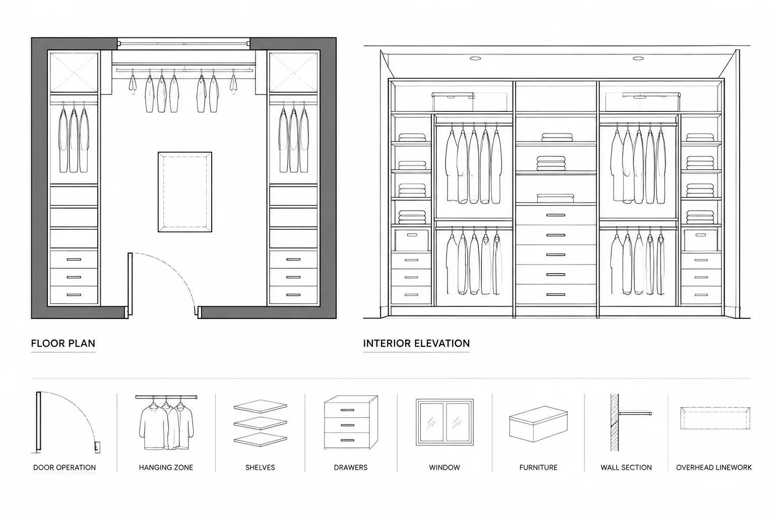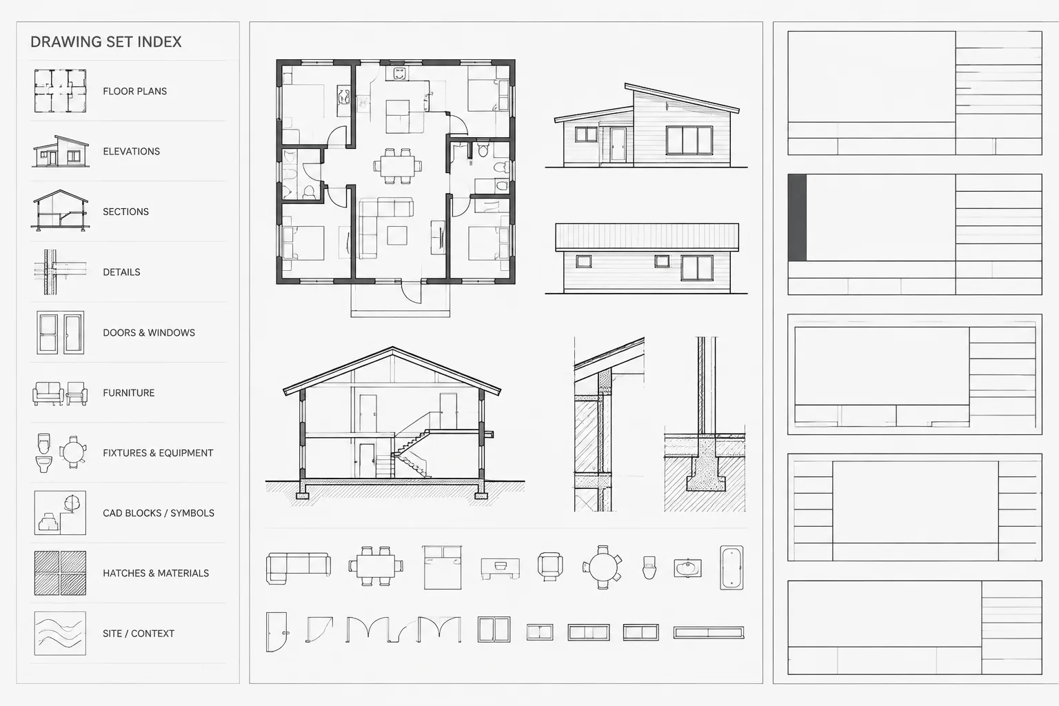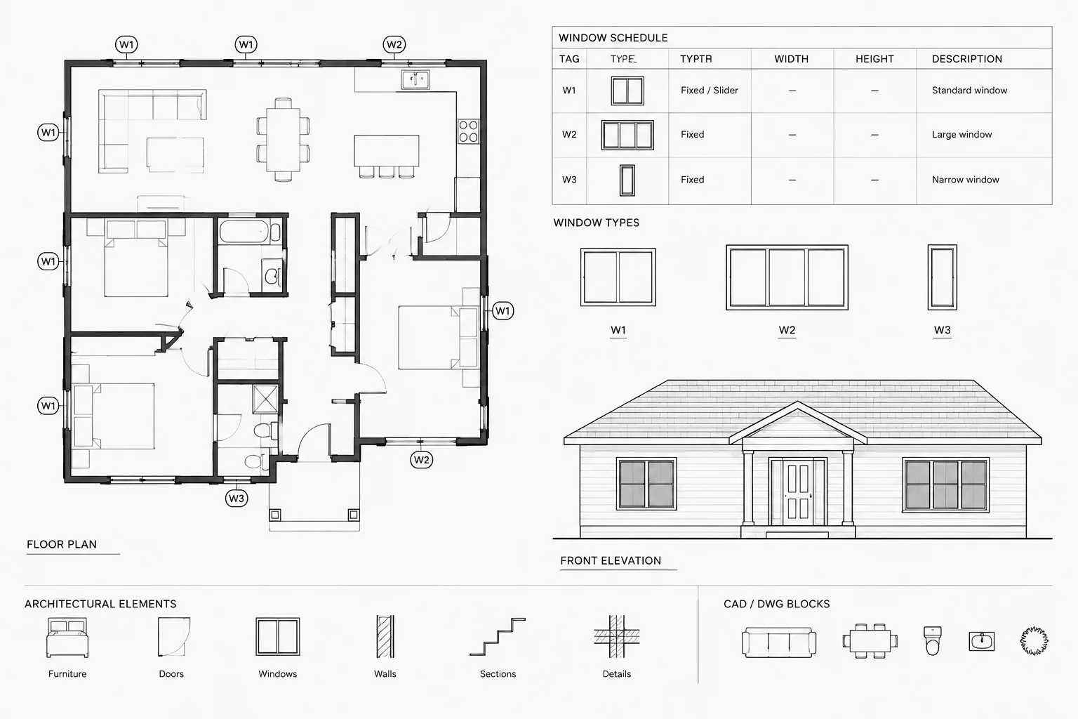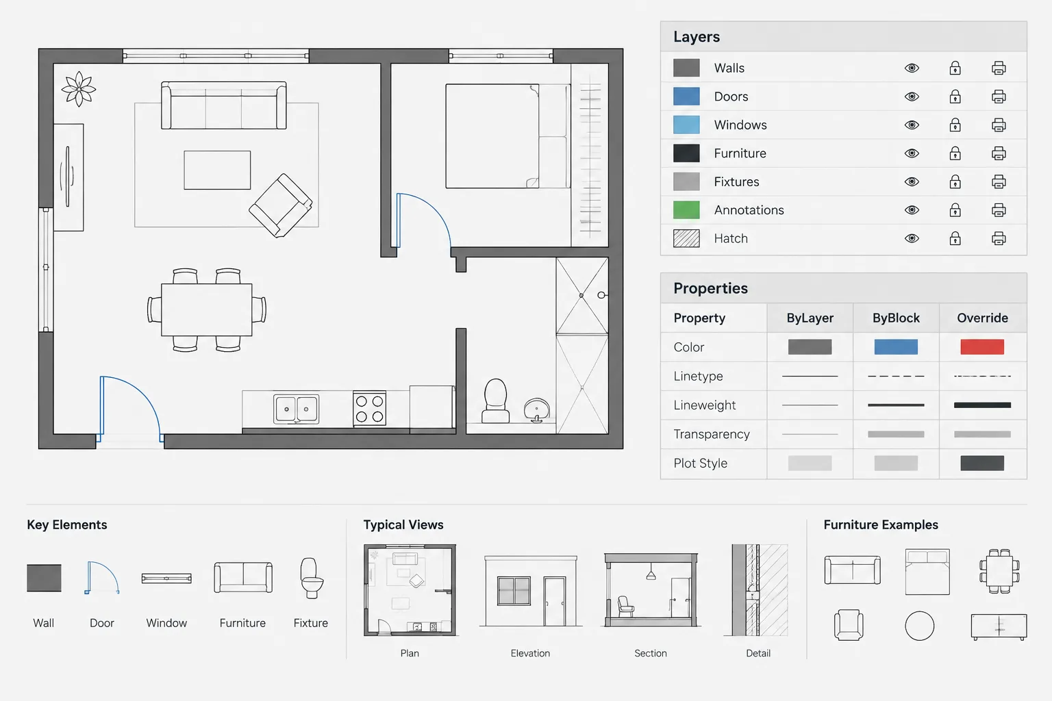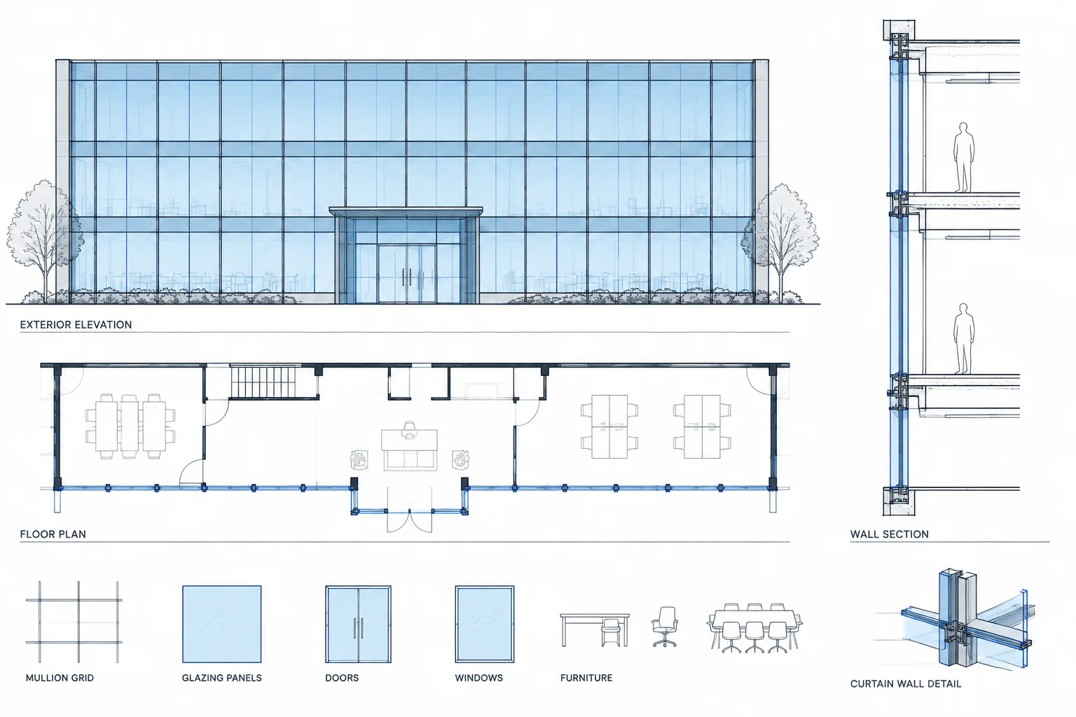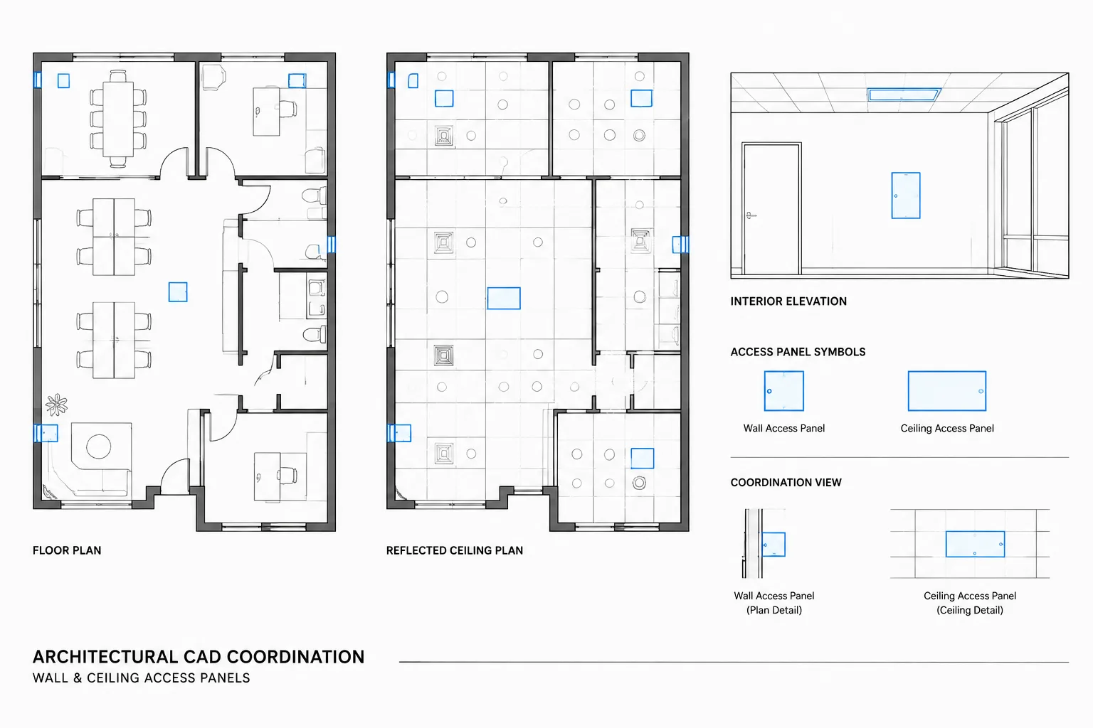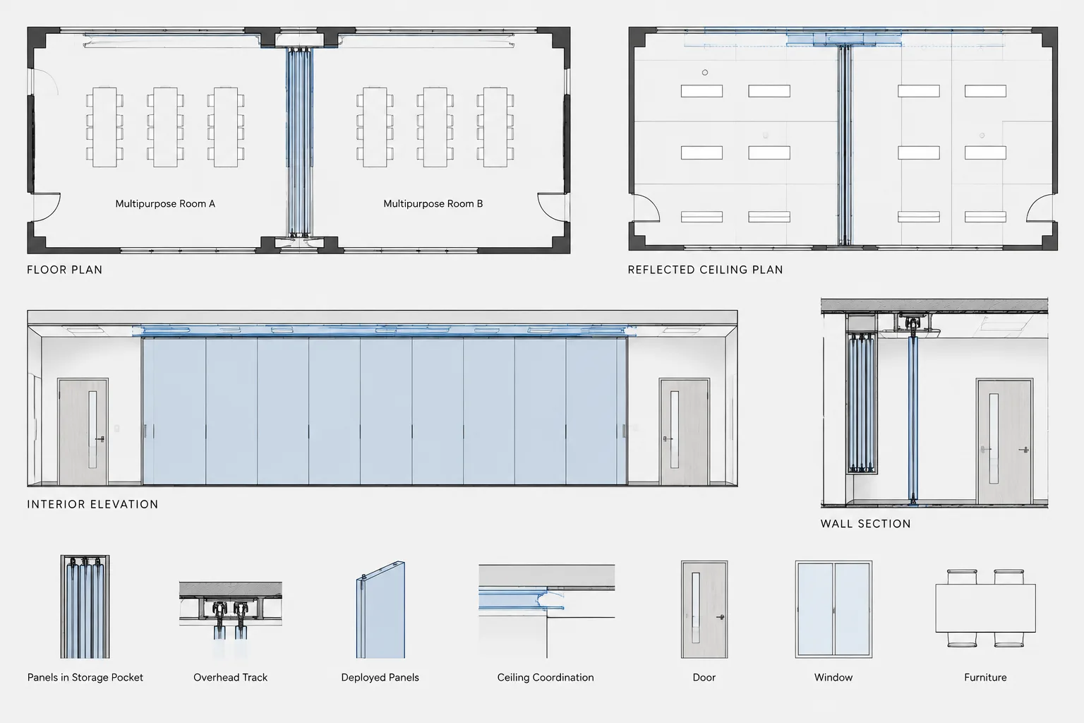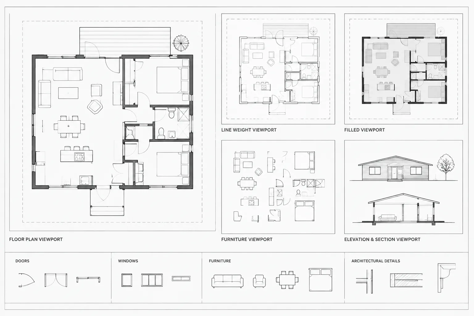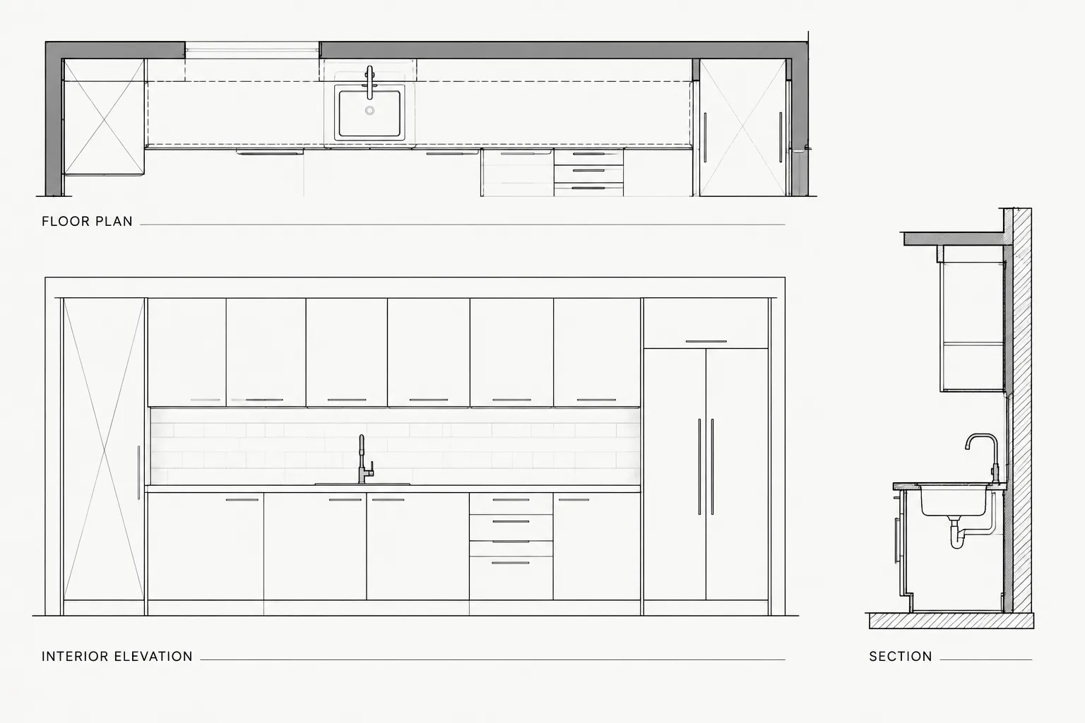
Drafting architectural casework in CAD requires more than arranging cabinet outlines. Each run must remain consistent across the floor plan, interior elevations, sections, schedules, equipment information, and utility backgrounds.
This guide explains how to establish reliable control points, organize casework geometry, coordinate adjacent systems, and review the completed drawing set without adding unsupported fabrication assumptions.
Architectural casework often appears simple in a floor plan, but a complete drawing package must communicate much more than a cabinet outline. Base units, wall-mounted cabinets, tall storage, countertops, fillers, finished end panels, equipment openings, and utility connections may need to align across several views. If those views are developed independently, conflicts can remain hidden until fabrication or installation.
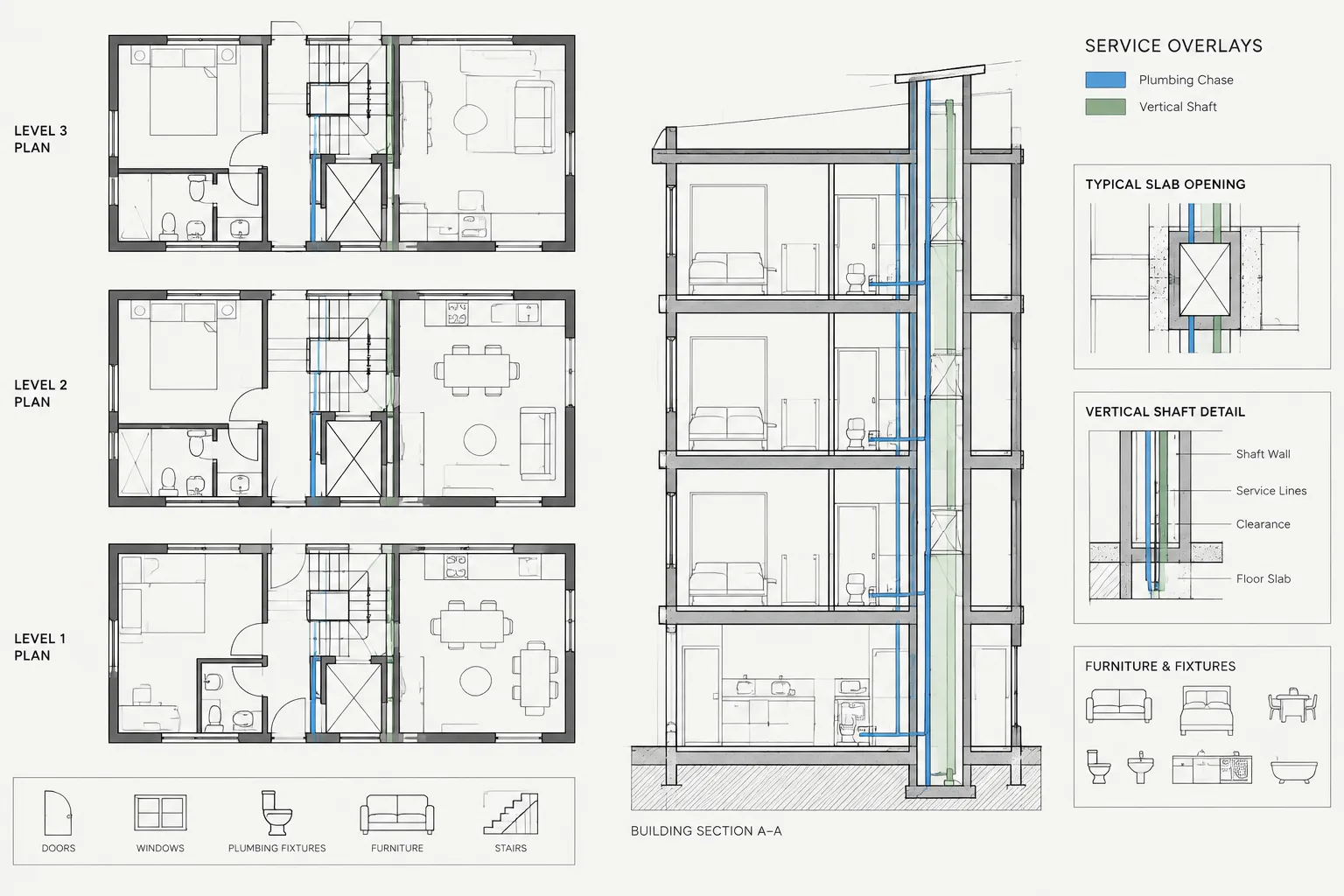
A reliable architectural casework CAD workflow treats the plan, interior elevation, section, detail, and schedule as coordinated representations of the same assembly. The goal is not to design the fabricator’s shop drawings. It is to define the architectural intent clearly enough for pricing, consultant coordination, product selection, and later submittal review.
Define the required level of information first
Before drafting individual cabinets, determine what the architectural documents need to establish. The answer depends on project phase, room type, procurement method, and drawing responsibility. Early layouts may show only the casework footprint and major equipment. Construction drawings usually need clearer information about configuration, interfaces, materials, and references.
Architectural drawings commonly identify:
- The overall casework location and extent
- Base, wall, and tall cabinet arrangements
- Countertop limits, edges, backsplashes, and changes in level
- Openings for sinks, appliances, equipment, or access panels
- Finished ends, exposed backs, fillers, and closure panels
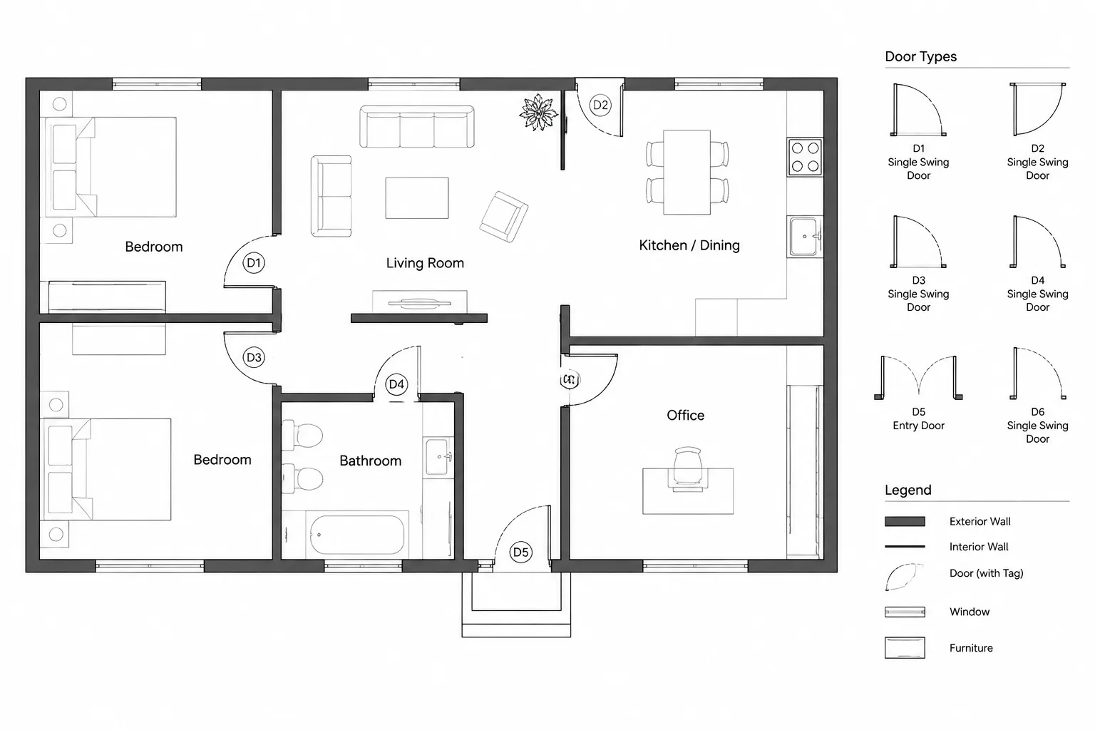
- Relationships to doors, windows, walls, and room finishes
- Section and detail references for important conditions
- Casework types, finish designations, or schedule references
Avoid adding fabrication assumptions merely to make the drawing look complete. Joinery, hardware, anchorage, substrate requirements, and internal construction may depend on the selected system, specification, structural support, or shop drawings. Show these items only when they are part of the verified design intent.
Start with a coordinated room background
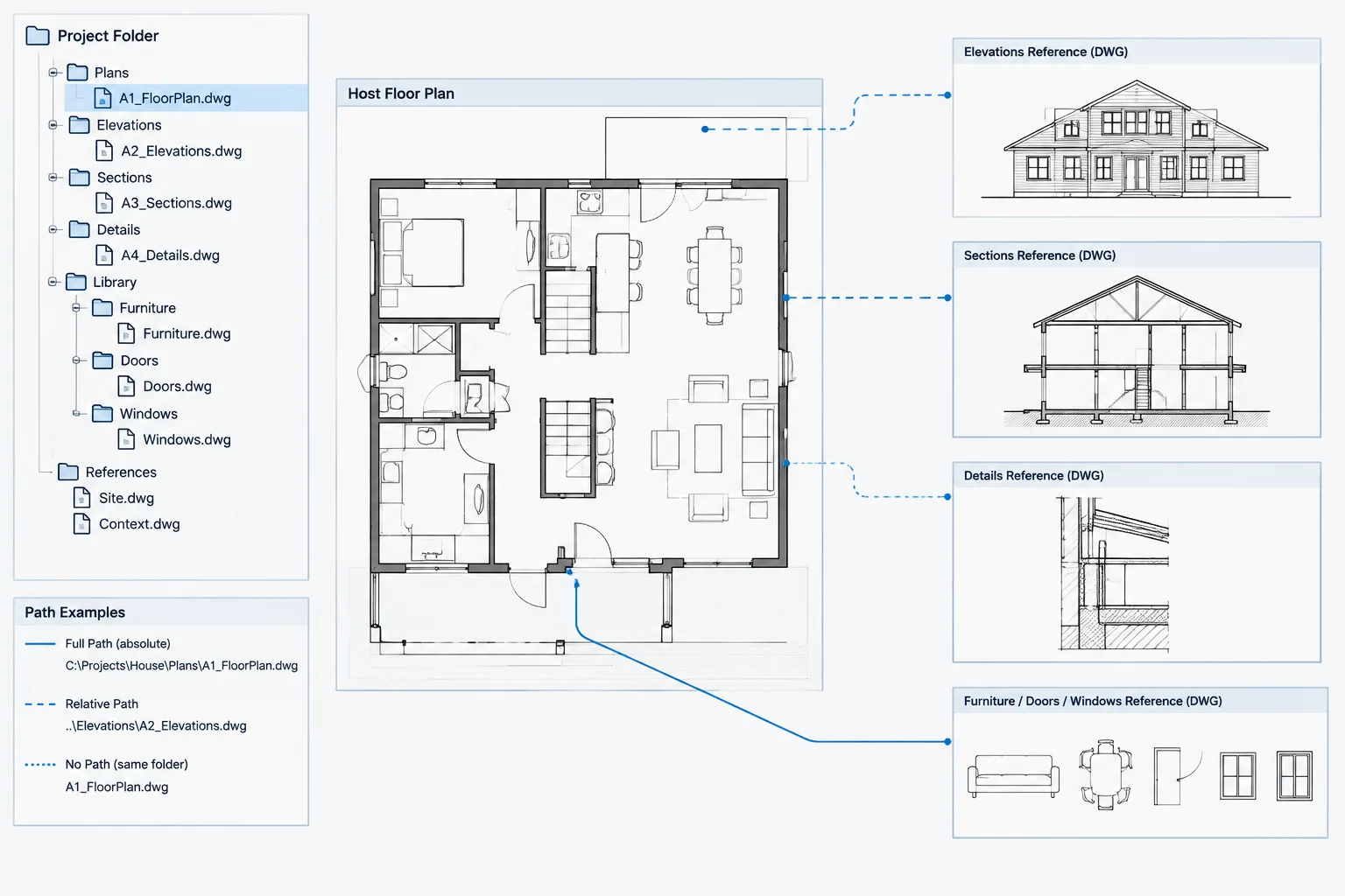
Casework should be developed against the current architectural background rather than drafted in isolation. Confirm wall faces, columns, openings, floor transitions, ceiling conditions, and fixed equipment before setting the cabinet run. If the room geometry is externally referenced, verify that the reference uses the project’s established origin, units, and orientation.
Also review nearby elements that may not be obvious on a basic floor plan. Window sills can affect counters and wall cabinets. Door swings can conflict with cabinet doors, drawers, or projecting handles. Wall-mounted devices may occupy the same elevation as upper cabinets. Soffits and ceiling transitions can influence tall units and overhead closures.
Build the casework layout in plan
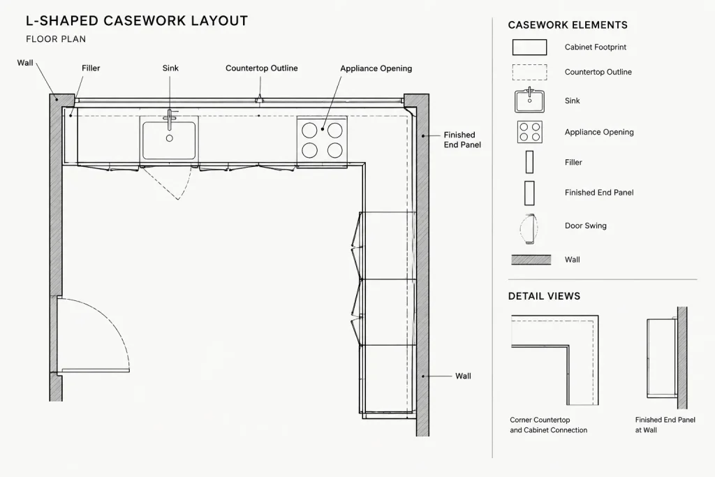
Establish the overall run
Begin with the total available wall length and the principal control points. These may include wall corners, structural elements, centered fixtures, equipment openings, plumbing locations, or an architectural alignment. Divide the run only after these controlling relationships are understood.
Use clean, closed geometry for cabinet footprints where practical. Separate countertops from cabinet boxes so that overhangs, seams, and changes in material can be edited without reconstructing the base units. Keep sinks, appliances, and specialty equipment as distinct objects or blocks rather than merging them into the casework linework.
Resolve ends and interruptions
The ends of a cabinet run deserve particular attention. A nominal sequence of standard units may not exactly fill the available space. The architectural layout should account for fillers, finished end panels, wall irregularities, projecting trim, and clearances needed for doors or drawers to operate.
At corners, show enough information to make the intended configuration understandable. A simple L-shaped counter outline does not explain whether the corner contains usable storage, a blind condition, an appliance, or an inaccessible void. The plan and interior elevation should tell the same story.
Use blocks selectively
Reusable blocks can improve speed and consistency for sinks, appliances, drawer banks, cabinet symbols, and repeated casework modules. However, a block should not conceal important project-specific geometry. If a generic block includes an unverified size, swing, label, or equipment configuration, revise or replace it before relying on it.
Keep block insertion points predictable. For casework modules, a back corner, centerline, or another intentional control point usually supports alignment better than an arbitrary point outside the visible geometry.
Develop interior elevations from the plan
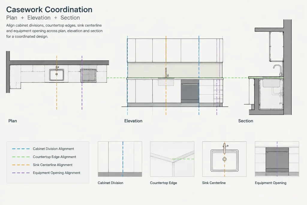
Interior elevations communicate the vertical organization that the plan cannot show. Use the plan as the controlling horizontal reference. Cabinet divisions, equipment edges, fillers, sink centerlines, and wall returns should align between views.
A useful elevation can distinguish:
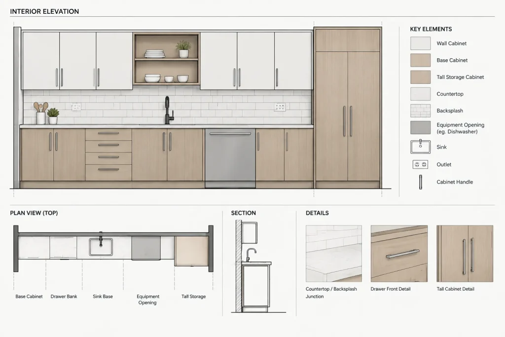
- Base cabinets, drawers, doors, and open compartments
- Wall cabinets, shelving, and tall units
- Countertops, backsplashes, and side splashes
- Finished panels, scribes, fillers, and closures
- Equipment faces and required openings
- Material or finish changes
- Relevant electrical, plumbing, and mounted accessories
Use lineweight and line type to establish depth. The nearest casework faces should read more strongly than wall surfaces or background elements. Hidden shelves or internal divisions should be shown only when they add necessary information; excessive hidden linework can make the elevation difficult to interpret.
Add sections where interfaces matter
A section is valuable when the assembly’s depth, support, or relationship to adjacent construction cannot be explained clearly in plan and elevation. Typical section locations include countertop edges, backsplashes, wall cabinet mounting zones, full-height storage, reception counters, accessible work surfaces, and casework beside glazing or wall panels.
Sections should focus on interfaces rather than repeating the elevation. Show how the casework meets the wall, floor, countertop, finish, and nearby construction. Identify support or backing requirements only when they have been coordinated with the responsible discipline and project documents.
Use detail callouts for conditions that need a larger view. Keep the parent section readable and avoid packing fabrication-level linework into a small-scale drawing.
Organize casework CAD layers
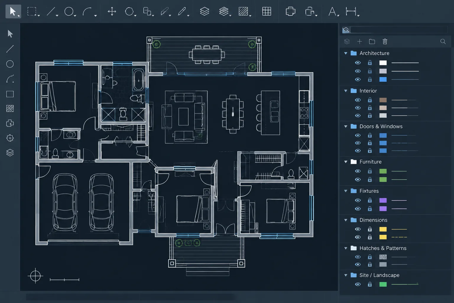
Layer organization should follow the project CAD standard, but casework information generally benefits from being separated by purpose. A practical structure may distinguish primary outlines, overhead units, concealed elements, countertops, equipment, annotations, dimensions, and reference geometry.
| Information group | Drafting purpose | Coordination benefit |
|---|---|---|
| Primary casework | Visible cabinet and panel outlines | Allows the main layout to be isolated and reviewed |
| Countertops | Edges, seams, openings, and material limits | Separates work-surface geometry from cabinet boxes |
| Overhead casework | Wall cabinets and elements above the plan cut | Supports appropriate overhead graphics |
| Equipment and fixtures | Sinks, appliances, and specialty components | Makes consultant and vendor coordination easier |
| Annotations | Tags, notes, dimensions, and references | Supports view-specific visibility and plotting |
Keep object properties controlled by layer unless a documented graphic exception is necessary. Random color, linetype, or lineweight overrides make later revisions and plotting checks more difficult.
Coordinate with equipment and building services
Casework frequently shares limited space with plumbing, electrical, data, mechanical, and specialty equipment. Coordination should occur before the architectural layout is treated as final.
- Confirm that sinks and plumbing components fit the intended cabinet zone.
- Review receptacles, switches, data outlets, and controls against cabinets and backsplashes.
- Check equipment access, ventilation, maintenance, and door or drawer operation using verified product information.
- Identify wall backing or support zones that require coordination.
- Review floor boxes, wall penetrations, and utility stub-ups against the current layout.
- Check ceiling devices and soffits above tall or wall-mounted units.
Do not infer service requirements from a generic CAD block. Use verified equipment data and the responsible consultant’s information. When a product has not been selected, clearly distinguish a planning allowance from a confirmed opening or connection.
Use tags and schedules without duplicating information
A casework tag can connect the drawing to an elevation, type, room-based identifier, or schedule entry. Choose a system that fits the size and complexity of the project. A small project may rely on keyed elevations and finish notes, while a larger project may benefit from distinct casework type designations.
Place each piece of information in one dependable location whenever possible. For example, the plan may control location, the elevation may control configuration, and a finish schedule may control exposed materials. Repeating the same note across several views creates multiple places that must be updated.
Run a focused casework quality-control review
Review the drawings by tracing each cabinet run through every relevant view. Start at one end of the run and compare the plan, elevation, section, tags, and schedule in sequence.
- Do cabinet divisions and equipment edges align between plan and elevation?
- Are countertop limits and openings consistent in every view?
- Are fillers, finished ends, and exposed backs identified where needed?
- Do doors and drawers have space to operate without obvious conflicts?
- Are casework tags unique and connected to the correct references?
- Do section markers point to the intended conditions?
- Are utilities coordinated with the current cabinet arrangement?
- Have obsolete options, hidden objects, and abandoned notes been removed?
- Does the plotted sheet maintain a clear hierarchy at its intended scale?
A final visual comparison is often more effective than checking isolated dimensions. Misaligned vertical divisions, shifted sinks, missing end panels, and contradictory equipment locations become easier to find when related views are placed side by side.
Keep architectural intent separate from shop drawings
Architectural casework CAD drawings define design intent and critical interfaces, but they are not automatically fabrication documents. Shop drawings may introduce manufacturer-specific construction, hardware, tolerances, support methods, and assembly logic. During submittal review, compare those drawings with the coordinated architectural plans, elevations, sections, finishes, and equipment requirements.
A disciplined workflow makes that review easier. When control points, type references, material boundaries, and interfaces are clearly documented, the project team can identify meaningful deviations without relying on assumptions hidden inside decorative linework.
Manage casework revisions as coordinated changes
Casework coordination continues after the initial layout is complete. A change to a sink, appliance, wall opening, countertop edge, or cabinet division may affect several drawings and consultant backgrounds. Treat each revision as a change to the entire assembly rather than as an isolated edit.
Identify the controlling information
Before revising a run, determine which information initiated the change and which view controls it. The room plan may establish location, an interior elevation may establish vertical organization, and verified equipment information may establish an opening or service zone. When these sources disagree, resolve the conflict instead of selecting the most convenient geometry.
Trace the change through related views
- Update the plan footprint, countertop, fixtures, and equipment.
- Revise corresponding cabinet divisions and alignments in the interior elevation.
- Review sections and enlarged details for affected interfaces.
- Check tags, finish references, notes, and schedule entries.
- Coordinate utility locations and support requirements with the responsible disciplines.
- Remove abandoned geometry and superseded annotations from the working file.
Record unresolved conditions clearly
Not every coordination question can be resolved immediately. Where information is pending, use the project’s established notation method to distinguish an allowance, design assumption, or coordination item from a confirmed requirement. This helps prevent preliminary geometry from being mistaken for verified product or fabrication information.
Prepare the CAD file for handoff and review
A clean file makes casework easier to review, revise, and reference. Before issuing the drawings, confirm that casework objects are placed on the intended layers, blocks use understandable insertion points, reference geometry is separated from deliverable linework, and annotations remain legible in the plotted view.
Review the drawing both as editable CAD geometry and as a plotted sheet. The file may be technically organized while the printed hierarchy remains unclear, or the sheet may appear correct while hidden duplicate objects and overrides complicate later revisions. Both conditions should be checked.
Frequently asked questions about architectural casework CAD
What should an architectural casework drawing communicate?
It should communicate the intended location, configuration, exposed finishes, countertop relationships, equipment interfaces, important openings, and references to related elevations, sections, details, or schedules. Fabrication methods should not be assumed unless they are part of the verified project requirements.
Should casework be drafted as blocks?
Blocks are useful for repeated modules, fixtures, equipment, and symbols, but they should remain easy to verify and edit. Generic blocks must be checked for inappropriate geometry, labels, swings, or product assumptions before use.
Which view should control the casework layout?
No single view controls every aspect. The plan typically establishes location and horizontal relationships, while elevations communicate vertical arrangement and sections explain depth and interfaces. The views must be coordinated as representations of the same assembly.
How should countertops be handled in CAD?
Keeping countertop geometry separate from cabinet boxes makes it easier to revise edges, openings, seams, material limits, and changes in level without rebuilding the underlying casework.
How is architectural casework different from shop drawings?
Architectural drawings define design intent and critical interfaces. Shop drawings typically develop the selected system’s fabrication, hardware, support, assembly, and installation information. Shop drawings should be reviewed against the coordinated architectural documents rather than treated as a replacement for them.
What are common casework coordination conflicts?
Common conflicts involve doors, drawers, wall openings, equipment, plumbing, electrical devices, access requirements, soffits, ceiling elements, finishes, and wall-mounted accessories. Verified consultant and product information should be used when resolving these conditions.