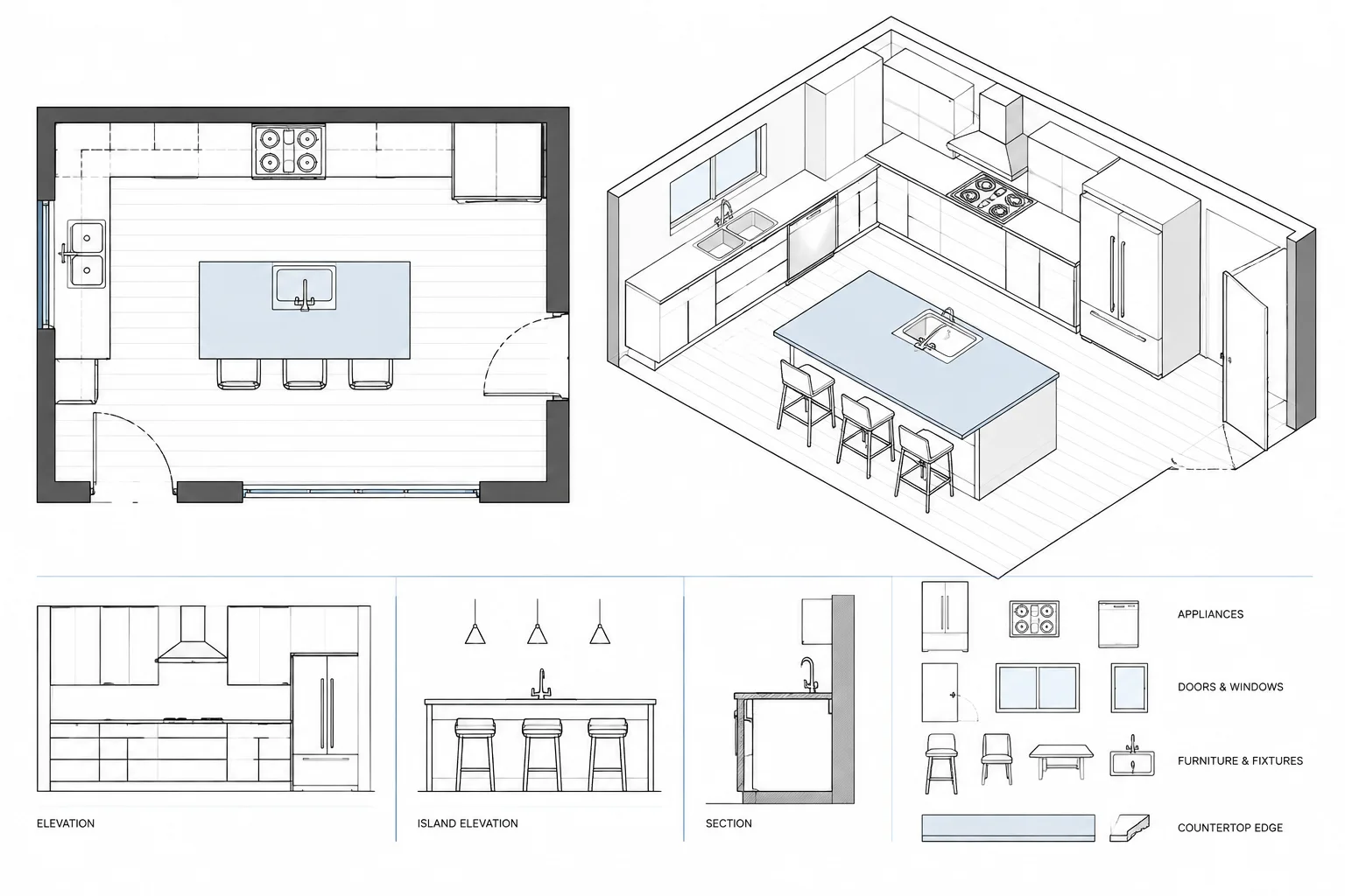
Drafting a kitchen requires more than placing cabinets, fixtures, and appliance symbols inside a room outline. Each component affects circulation, adjacent construction, utility coordination, overhead conditions, and the information shown in related elevations and schedules.
This guide presents a practical workflow for developing a kitchen plan in architectural CAD. It emphasizes dependable background geometry, disciplined file organization, deliberate cabinet and countertop drafting, and coordinated review across architectural and consultant drawings.
A kitchen plan brings together architecture, casework, appliances, plumbing, electrical work, finishes, and circulation in a relatively small area. A drawing can look complete while still containing conflicts between cabinet modules, door swings, equipment connections, countertop edges, and adjacent construction.
A reliable kitchen plan in architectural CAD should therefore be treated as a coordination drawing rather than a simple arrangement of cabinet and appliance blocks. The drafting process should begin with verified project geometry, proceed through functional zones and component layouts, and end with cross-checks against elevations, schedules, consultant drawings, and manufacturer information.
Start with a dependable architectural background
Before laying out cabinets, confirm that the background represents the current design. Kitchen planning based on an obsolete wall location or uncoordinated shaft can lead to widespread revisions later.
Review the following background information:
- Finished faces of walls, columns, and permanent enclosures
- Door locations, swings, frames, and adjacent openings
- Window locations and sill conditions that may affect countertops or fixtures
- Structural elements, shafts, risers, and plumbing chases
- Floor elevation changes and finish transitions
- Ceiling conditions that may affect tall cabinets or exhaust systems
- Relevant grids, room numbers, and reference dimensions
If the kitchen is being drafted in a separate DWG file, use a controlled architectural background reference rather than copying disconnected geometry. Keep the reference path, insertion point, units, and rotation consistent with the project workflow.
Separate fixed conditions from planned components
Organize the file so that permanent construction can be distinguished from kitchen-specific content. The exact layer names should follow the office or project standard, but separate control is useful for:
- Base, wall, and tall cabinets
- Countertops and backsplashes
- Appliances and equipment
- Plumbing fixtures
- Clearance and service zones
- Overhead items
- Tags, dimensions, and notes
- Existing or demolition work when applicable
This separation makes it easier to prepare different plan views, such as a general architectural plan, enlarged kitchen plan, equipment plan, or finish plan. It also prevents clearance outlines and coordination graphics from appearing unintentionally on issued sheets.
Lay out the kitchen by functional zones
Instead of beginning with individual cabinet blocks, identify the main activities that the kitchen must support. Residential and commercial kitchens differ substantially, but both benefit from a zone-based review.
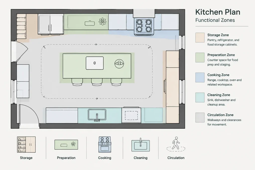
Storage
Locate food storage, refrigerated storage, pantry space, and general cabinet storage. Consider how doors and drawers operate and whether nearby walls, handles, trim, or projecting equipment restrict access.
Preparation
Identify continuous work surfaces and the relationship between preparation areas, sinks, cooking equipment, and storage. Countertop geometry should be drawn deliberately rather than inferred from cabinet lines.
Cooking
Place cooking equipment using verified product or design information. Coordinate exhaust requirements, adjacent surfaces, overhead construction, and utility needs with the responsible consultants and manufacturers.
Cleaning
Coordinate sinks, dishwashing equipment, waste storage, and nearby plumbing routes. Show enough information to identify the intended relationship without using the architectural plan to guess concealed piping layouts.
Circulation and access
Review routes through and around the kitchen, including paths to adjacent rooms. Add temporary clearance zones for open doors, drawers, equipment panels, and opposing work areas. Required clearances must be established from the applicable project criteria and regulations rather than assumed from a generic CAD block.
Build a clear cabinet and countertop plan
Cabinet lines should communicate more than a row of rectangles. Use consistent graphics to distinguish base cabinets, wall cabinets, tall units, open shelving, panels, fillers, and overhead elements.
A practical sequence is:
- Establish countertop edges and major appliance openings.
- Lay out base cabinet runs between verified endpoints.
- Add tall cabinets and full-height panels.
- Place wall cabinets and other overhead components.
- Resolve corners, fillers, end panels, and wall irregularities.
- Assign cabinet identifiers if a schedule or elevation system is used.
Do not force a cabinet run to fit by scaling cabinet blocks. Scaling can distort door widths, symbols, annotation, and represented construction. Adjust the layout using appropriately defined units or project-specific geometry.
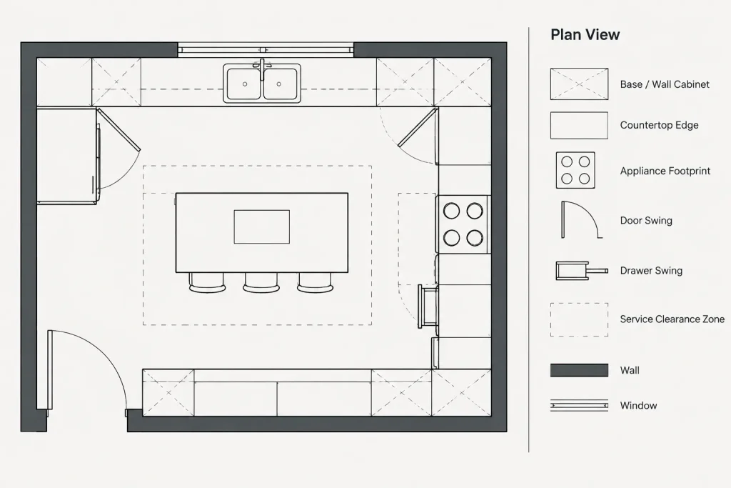
Countertops should account for exposed ends, wall returns, islands, penetrations, and changes in depth or height. Confirm whether a line represents the cabinet face, door face, countertop edge, or overhead projection. Ambiguous parallel lines are a frequent source of field questions.
Use equipment blocks as coordination tools
Appliance and equipment blocks should have predictable insertion points, orientation, and graphic extents. A useful insertion point might relate to a finished wall, cabinet opening, centerline, or equipment corner, depending on the project workflow.
Before relying on a downloaded or legacy block, verify:
- Drawing units and scale
- Overall footprint
- Door or panel swing
- Required adjacent space
- Connection or service side
- Whether the block depicts a generic object or a selected product
- Whether concealed lines and overhead graphics plot appropriately
Do not assume that a visually detailed block is accurate. Product selections can change, and manufacturer drawings may represent nominal, installation, or shipping dimensions differently. Record the source and status of critical equipment information within the project coordination process.
Show operating and service clearances carefully
A closed appliance footprint rarely describes its full spatial impact. Refrigerators, ovens, dishwashers, cabinet doors, and drawers may project into circulation areas when open. Some equipment also needs access for installation, ventilation, cleaning, or maintenance.
Place these extents on a dedicated non-plot or selectively plotted layer. Use restrained linework so the plan remains readable. Clearance outlines should be understood as coordination aids, not automatic proof of compliance. Confirm them against current product information, project requirements, and applicable regulations.
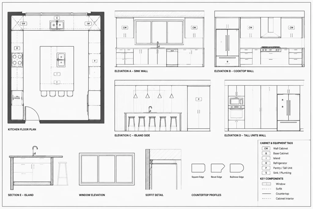
Coordinate the plan with elevations and sections
The floor plan establishes horizontal relationships, but many kitchen conflicts are vertical. Interior elevations and sections should be developed while the plan is still changing, not after it is considered finished.
| Plan item | Elevation or section check |
|---|---|
| Wall cabinets | Relationship to ceilings, soffits, windows, and adjacent tall units |
| Countertops | Thickness, edge conditions, supports, and changes in level |
| Sink and fixtures | Backsplash, window, mirror, shelf, and plumbing relationships |
| Cooking equipment | Exhaust, overhead cabinet, wall finish, and utility coordination |
| Refrigeration | Enclosure, ventilation, door operation, and adjacent panel conditions |
| Islands and peninsulas | Supports, overhangs, outlets, finish transitions, and ceiling alignment |
Use matching identifiers between plan tags and elevation references. If cabinet or equipment numbers appear in multiple views, keep the naming consistent with schedules and specifications.
Coordinate related disciplines without overcrowding the plan
The architectural kitchen plan should show the information needed to define design intent while allowing discipline-specific drawings to carry their own detailed systems.
- Plumbing: Confirm fixture locations, chases, floor penetrations, and equipment connection zones.
- Electrical: Coordinate equipment power, countertop devices, switching, and conflicts with cabinets or backsplashes.
- Mechanical: Review exhaust paths, grilles, diffusers, shafts, and ceiling conflicts.
- Lighting: Align fixtures with work areas, cabinets, ceiling features, and reflected ceiling plans.
- Structural: Review island supports, wall backing needs, penetrations, and unusual concentrated conditions with the responsible designer.
- Interiors: Coordinate finishes, hardware, decorative lighting, panels, and visible equipment selections.
Avoid copying every consultant symbol into the architectural file. Use external references or coordinated backgrounds where appropriate, and add only the architectural information required to explain the layout.
Dimension from stable references
Dimension the kitchen so that the intended layout can be interpreted without chaining every cabinet width across the room. Favor stable references such as finished wall faces, column lines, opening edges, and established centerlines.
Useful dimension targets may include:
- Overall limits of cabinet runs
- Equipment openings and centerlines
- Island or peninsula location
- Countertop edges where they control circulation
- Sink and fixture centerlines
- Critical wall returns, fillers, and clearances
Coordinate dimensions with the cabinet elevations and schedules. Duplicate dimensions can become inconsistent when revisions are made, so each critical condition should have a clear controlling location.
Run a focused kitchen plan quality check
Before issuing the drawing, perform a review with all relevant references visible. A useful checklist includes:
- Confirm that walls, doors, windows, and shafts match the current architectural background.
- Check that cabinet runs close correctly at walls, corners, and equipment openings.
- Review appliance doors, cabinet doors, and drawers in open positions.
- Compare equipment tags with the current equipment or appliance schedule.
- Verify plan geometry against interior elevations and sections.
- Check countertop, backsplash, and finish boundaries.
- Review plumbing, electrical, mechanical, lighting, and structural overlays.
- Confirm that overhead elements use a clear drafting convention.
- Inspect dimensions for missing, duplicate, or conflicting information.
- Plot a test sheet to confirm lineweights, hatches, tags, and clearance graphics.
A well-coordinated kitchen plan is not simply a collection of attractive blocks. It is a controlled drawing that communicates fixed construction, planned components, operating space, and references to related information. Building the plan around verified geometry and purposeful coordination reduces ambiguity and makes later revisions easier to manage.
Manage revisions as coordinated drawing changes
Kitchen layouts often evolve as equipment, finishes, casework, and adjacent rooms are refined. A revision should therefore be reviewed as a group of related changes rather than as an isolated edit. Moving an appliance may affect its cabinet opening, countertop, utility location, elevation, tag, schedule entry, clearance outline, and nearby dimensions.
After changing the plan, trace the edited condition through every drawing that describes it. This review is especially important where the same object appears in plans, elevations, sections, reflected ceiling plans, finish information, and consultant backgrounds.
Use a controlled revision sequence
- Identify the project decision or updated source behind the change.
- Revise the controlling plan geometry without stretching or scaling fixed-size component symbols.
- Update associated countertops, panels, fillers, clearances, tags, and dimensions.
- Compare the changed area with interior elevations and sections.
- Review affected equipment, finish, and casework schedules.
- Notify relevant disciplines when connection points, penetrations, exhaust routes, or ceiling relationships may be affected.
- Plot the revised view and inspect it at its intended sheet presentation.
Distinguish design intent from product information
The architectural plan communicates the intended arrangement and relationships, while selected-product information may provide installation details that should not be reconstructed from a generic block. Keep the status of each component clear. A placeholder appliance, a design-basis item, and a confirmed selection should not be treated as equally verified information.
Where product-dependent geometry controls the layout, record its source through the established project documentation process. If information remains unresolved, use clear notes or coordination markers rather than drawing unsupported detail that could be mistaken for a confirmed requirement.
Check drawing readability as well as geometry
A technically coordinated plan can still be difficult to use if cabinet edges, countertop outlines, overhead items, clearance graphics, and background construction compete visually. Apply a consistent graphic hierarchy so permanent construction reads clearly, planned components remain identifiable, and secondary coordination information stays subordinate.
Review the sheet without relying on layer colors alone. Printed or exported output should make it possible to distinguish object boundaries, overhead projections, open-position graphics, tags, dimensions, and references through linework and annotation conventions.
Prepare the kitchen plan for project handoff
Before sharing or archiving the file, remove unexplained construction geometry, confirm that references resolve correctly, and check that blocks and layers follow the project workflow. Keep important component identifiers consistent across the drawing set so another drafter can understand what controls the layout and where supporting information is located.
The final goal is not merely a clean CAD file. It is a coordinated drawing record that allows architects, consultants, fabricators, contractors, and reviewers to interpret the intended kitchen arrangement without relying on assumptions hidden outside the issued documents.
Frequently Asked Questions
Should cabinets be drafted before appliances are placed?
Establish the major equipment locations and countertop relationships before completing cabinet runs. Appliance openings, panels, fillers, corners, and wall conditions can all influence how the surrounding casework is resolved.
Can a downloaded appliance block be used without checking it?
No. Confirm its units, footprint, orientation, insertion point, operating graphics, and product status. A detailed-looking block may still be generic, outdated, or inconsistent with the selected equipment.
Where should appliance door swings and service zones be drawn?
Place them on a dedicated layer that can be displayed for coordination and hidden when inappropriate for the issued view. These graphics help identify conflicts but do not replace verification against project criteria and current product information.
Why should kitchen elevations be developed alongside the plan?
The plan resolves horizontal placement, while elevations and sections reveal relationships involving wall cabinets, windows, soffits, ceilings, backsplashes, exhaust components, and tall equipment. Developing the views together exposes conflicts earlier.
What references are best for kitchen dimensions?
Use stable project geometry such as finished wall faces, opening edges, columns, and established centerlines. Avoid unnecessary dimension chains that can spread small revisions across an entire cabinet run.
How can an architectural kitchen plan avoid becoming overcrowded?
Separate content by layer and drawing purpose. Show the architectural information needed to communicate the layout, while using coordinated consultant references for discipline-specific systems. Keep temporary clearance and review graphics selectively visible.