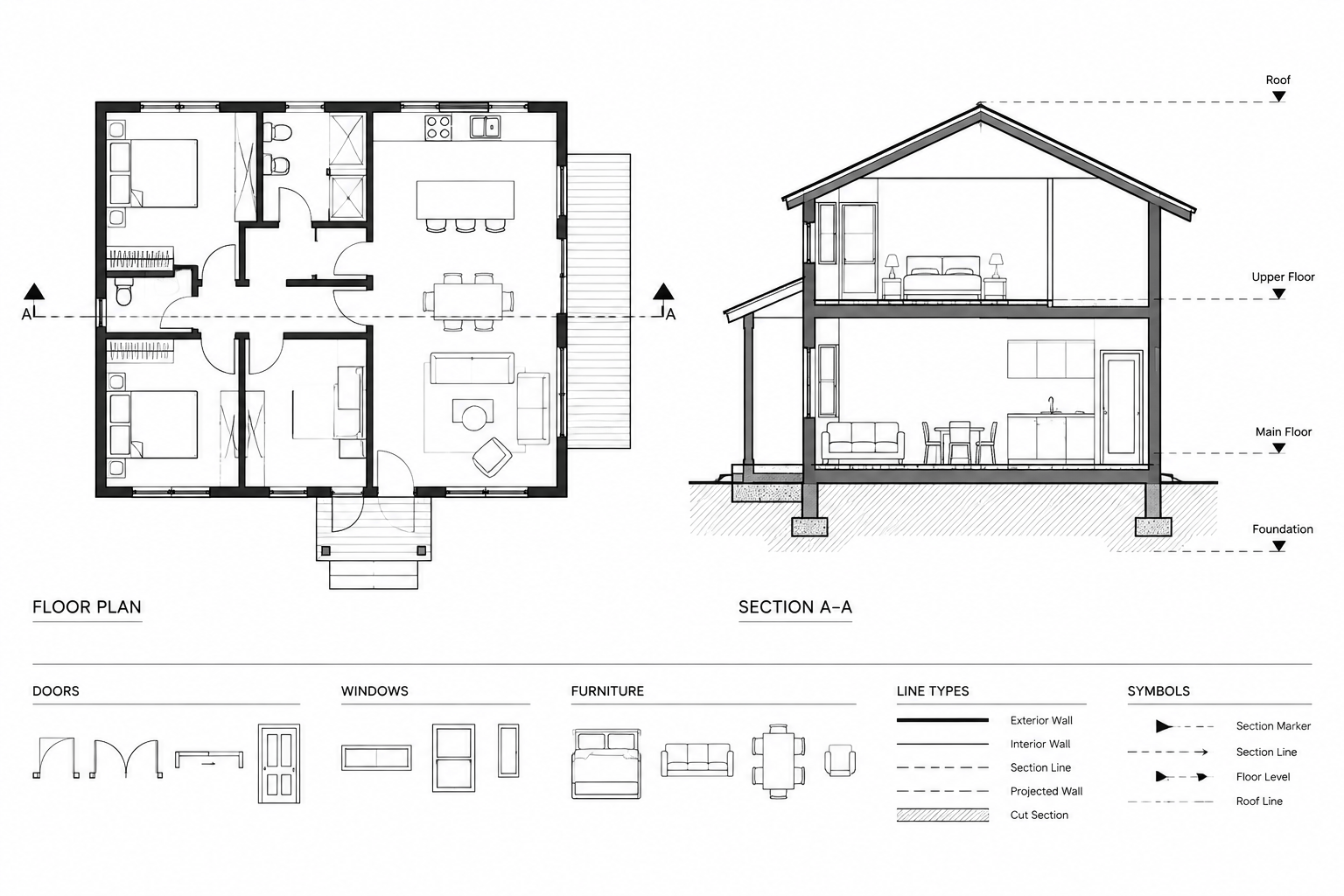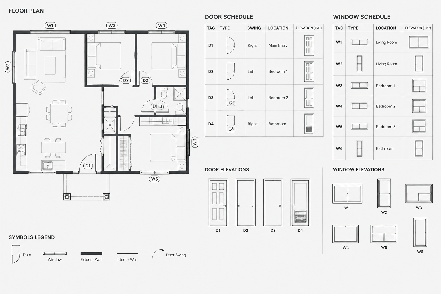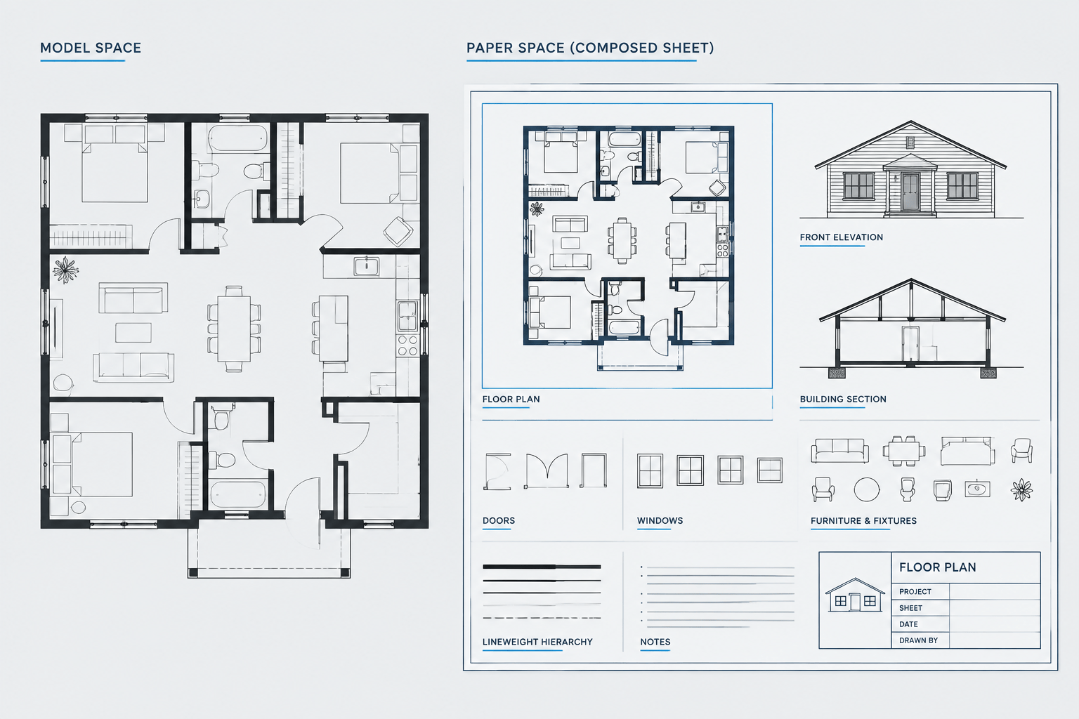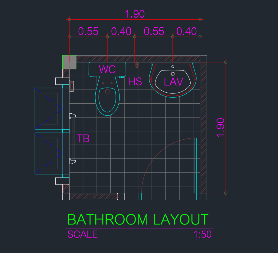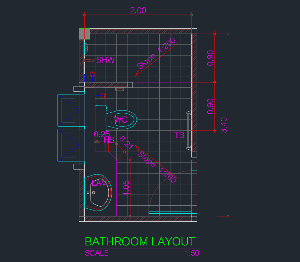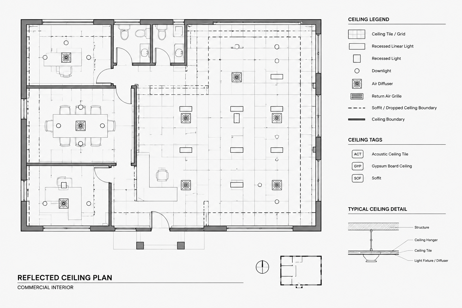
A reflected ceiling plan, commonly abbreviated as RCP, communicates what is happening overhead within a building. It can show ceiling types, changes in elevation, soffits, lighting locations, air devices, access panels, and other coordinated elements. Although an RCP often begins with the architectural floor plan, it should become a purpose-built drawing rather than a copy filled with ceiling symbols.
A clear reflected ceiling plan CAD workflow separates background information from overhead work, establishes a readable graphic hierarchy, and makes coordination changes easier to track. The exact drawing scope varies by project and discipline, so every RCP should be checked against the project requirements, consultant documents, manufacturer information, and applicable regulations.
What a Reflected Ceiling Plan Represents
An RCP is drawn as though the ceiling is projected onto a horizontal plane for viewing. It is not simply a floor plan mirrored across the sheet. The room arrangement generally maintains the same orientation used on the corresponding floor plan so that walls, doors, room names, and reference markers remain easy to compare between drawings.
The drawing focuses on overhead conditions. Depending on the project, the architectural RCP may include:
- Ceiling material or system boundaries
- Suspended ceiling grids or panel patterns
- Open-to-structure areas
- Bulkheads, soffits, coves, and ceiling steps
- Architectural lighting intent and fixture symbols
- Supply, return, and exhaust air-device locations for coordination
- Sprinklers and other life-safety devices when supplied by the responsible consultant
- Speakers, detectors, sensors, cameras, and related ceiling-mounted devices
- Access panels and maintenance zones
- Curtain tracks, ceiling-mounted partitions, or specialty equipment
- Ceiling tags, notes, elevations, dimensions, and detail references
Not every item belongs on every architectural sheet. Consultant-designed systems should be represented only to the level required for coordination or documentation. Their final selection, engineering, and compliance remain the responsibility of the appropriate project professional.
Prepare the Floor Plan Background
Begin with a coordinated floor plan background. Walls, columns, shafts, stairs, room boundaries, and major openings should align with the current architectural model or drawing. Using a referenced background can help prevent the ceiling plan from becoming an independent copy that stops matching the floor plan.
Reduce the graphic prominence of background elements. Walls may remain visible for orientation, but furniture, floor finishes, loose equipment, and minor floor-level details often add clutter without helping ceiling coordination. Door swings may be retained where they clarify room access, although they should not compete with overhead information.
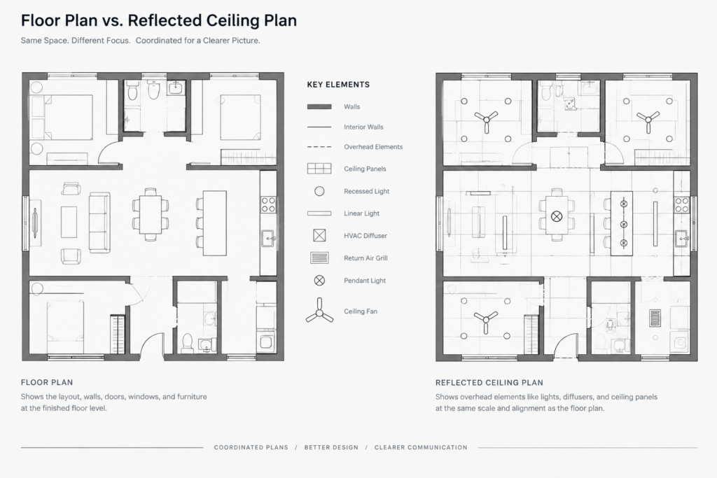
Before drafting ceiling work, confirm:
- The drawing origin and orientation match the floor plan.
- The background represents the correct level and revision.
- Room names and numbers are coordinated.
- Demolition, existing, and new construction are clearly distinguished when relevant.
- Annotation intended only for the floor plan is hidden or placed on separate layers.
Build the Ceiling Geometry by Room or Zone
Define ceiling boundaries first
Draw the perimeter of each ceiling type before inserting fixtures. Boundaries may follow walls, stop at soffits, wrap around structural elements, or transition between materials. Closed, clean boundaries make patterns and hatches easier to manage and help reveal gaps or overlaps.
Avoid relying on a hatch alone to define a ceiling area. A separate boundary line provides a stable object for editing and can remain legible if the hatch is turned off for coordination.
Establish grids from a deliberate control point
For modular ceiling systems, select a grid origin based on architectural intent. A grid may be centered in a room, aligned with a corridor, related to a wall feature, or coordinated across connected spaces. The best origin is not always the geometric center; it should support the design and minimize awkward perimeter conditions where practical.
Construct the grid accurately rather than using a generic pattern that is visually stretched to fit. Keep grid linework separate from ceiling boundaries so that either can be revised without rebuilding the other.
Show ceiling changes clearly
Use distinct linework for soffits, ceiling steps, coves, and open edges. A ceiling elevation tag should identify the level associated with a ceiling area, while notes or detail references can explain construction that cannot be understood in plan alone. Where multiple levels occur close together, place tags carefully so their ownership is unambiguous.
Organize RCP Information with Layers
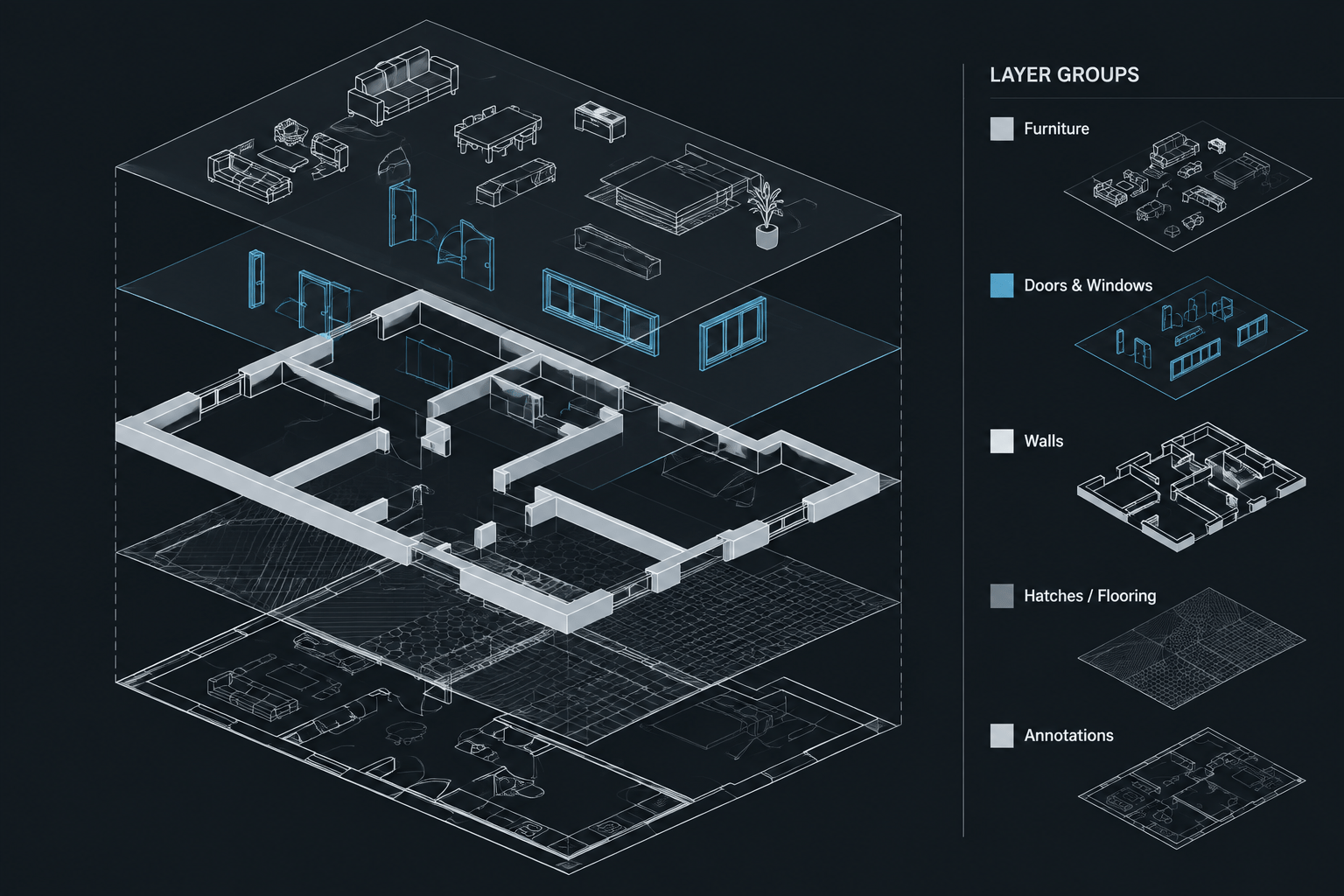
Layer names should follow the office or project convention. The important principle is to separate elements by function so they can be displayed, checked, and plotted independently. A practical structure may distinguish the following categories:
| Layer category | Typical content | Coordination purpose |
|---|---|---|
| Ceiling boundaries | Edges of materials and ceiling zones | Defines the extent of each system |
| Ceiling grids or patterns | Panel joints, grid lines, or directional patterns | Supports fixture and device alignment |
| Overhead features | Soffits, coves, bulkheads, and ceiling openings | Communicates changes in form |
| Lighting | Fixture symbols and architectural lighting references | Allows layout and switching coordination |
| Mechanical coordination | Diffusers, grilles, and other air devices | Identifies conflicts with lights and grids |
| Other devices | Detectors, speakers, sprinklers, sensors, and cameras | Supports multidisciplinary coordination |
| Annotations | Ceiling tags, notes, dimensions, and keynotes | Keeps documentation separate from geometry |
| Background | Walls, columns, room identifiers, and openings | Provides orientation without dominating the sheet |
Avoid placing all overhead devices on one layer merely because they appear on the same plan. Discipline-based or system-based separation makes it easier to isolate conflicts, apply graphic standards, and incorporate consultant updates.
Place Fixtures and Devices as Coordinated Blocks
Use consistent CAD blocks for repeated ceiling components. Each block should have a logical insertion point, predictable orientation, and geometry appropriate to the drawing scale. The insertion point might correspond to the device center, mounting point, or another documented control location.
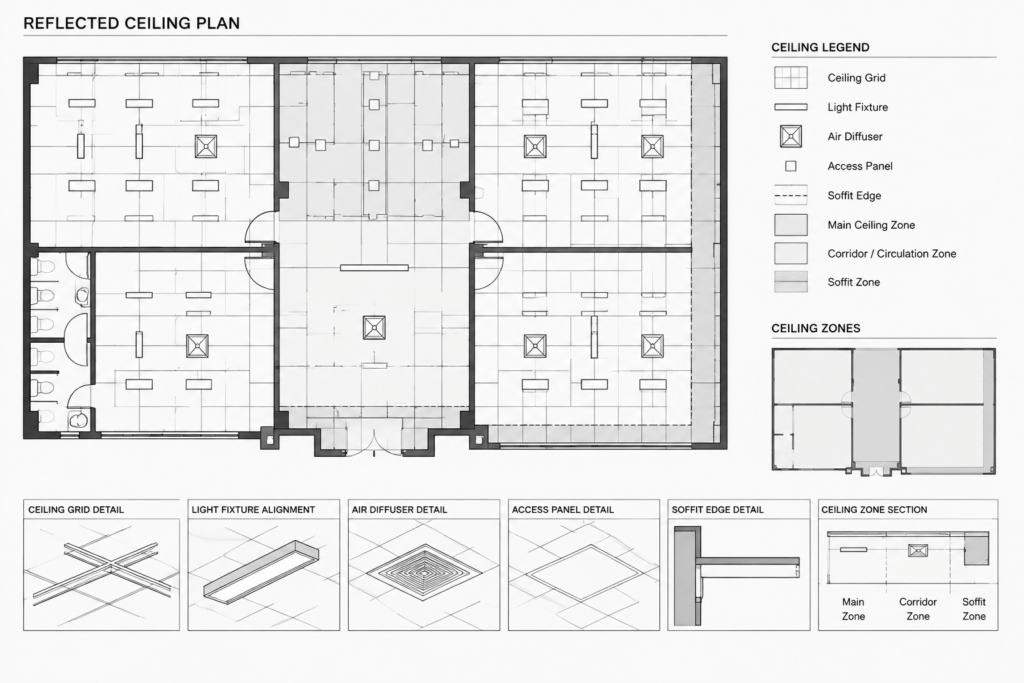
Do not assume that a downloaded block has the correct size, units, symbol convention, or technical meaning. Inspect and standardize it before use. A symbol may represent an item diagrammatically rather than reproduce the physical product outline, so the block and its associated schedule or legend must agree.
Place dominant architectural elements first. Major lights, continuous fixtures, ceiling features, and large air devices often establish the organizing pattern. Secondary devices can then be coordinated around them. This sequence is more reliable than filling the ceiling with individual symbols without considering the overall composition.
Coordinate rather than merely center
Centering every device in a ceiling panel does not automatically produce a coordinated plan. Consider the relationships among fixture rows, grid intersections, room axes, casework, partitions, doors, equipment, and focal features. In irregular rooms, a clear controlling alignment may be more useful than several unrelated centered objects.
Where devices overlap or occupy incompatible locations, resolve the conflict with the responsible disciplines instead of shifting symbols arbitrarily. The final drawing should represent an agreed arrangement, not just a graphically tidy one.
Annotate the RCP Without Overloading It
Ceiling tags commonly identify a type, elevation, or both, depending on the project system. Keep tag formatting consistent and position tags within the areas they describe. If one ceiling type occurs in several disconnected areas, tag enough locations to prevent uncertainty.
Dimensions should communicate layout controls that installers or reviewers cannot reliably derive from the drawing. Useful dimension targets may include:
- Ceiling feature edges
- Centers of major fixtures or grouped devices
- Grid control points
- Soffit widths and offsets when defined by the design
- Openings and access panels that require specific coordination
Avoid dimensioning every grid line or repeated device if the controlling pattern is already clear. Excessive dimensions can hide conflicts and make future revisions difficult. Notes should explain exceptions or drawing conventions, while repeated technical information is usually better handled through legends, schedules, or keyed details.
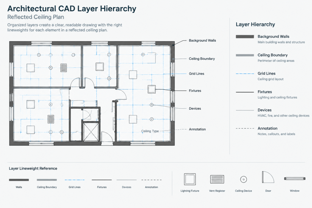
Create a Clear Graphic Hierarchy
The reflected ceiling information should read before the floor plan background. Ceiling boundaries and important overhead features generally need greater visual emphasis than grids and secondary devices. Hatches should remain light enough that symbols and tags are visible. Consultant coordination symbols should be distinguishable without overwhelming architectural intent.
Always review the RCP at its intended plotted scale. A plan that appears clear when enlarged on screen may become dense or illegible on a sheet. Check lineweights, hatch spacing, text size, symbol clarity, and overlaps through a test plot or plot preview.
Quality-Control Checklist for a Reflected Ceiling Plan
Before issuing the drawing, compare the RCP with the floor plan, elevations, sections, schedules, and current consultant information. A focused review should include the following:
- Every enclosed room has a defined ceiling condition or an intentional open condition.
- Ceiling boundaries agree with walls, soffits, shafts, and major built-in elements.
- Grid patterns terminate cleanly and use an intentional origin.
- Ceiling tags match the project ceiling legend or schedule.
- Ceiling levels agree with sections, elevations, and interior details.
- Lights and other devices do not unintentionally overlap.
- Access panels are coordinated with equipment requiring service.
- Major devices are not concealed by tags, dimensions, or hatches.
- Room names and numbers match the corresponding floor plan.
- Background linework is visually subordinate.
- Detail and section references point to the correct conditions.
- Revision clouds or issue annotations do not obscure critical information.
Common RCP Drafting Mistakes
One frequent mistake is treating the reflected ceiling plan as a late-stage copy of the floor plan. This tends to produce duplicated annotation, uncontrolled backgrounds, and ceiling information that does not respond to the architecture. Another is using visual alignment without object snaps or established control lines, which can leave rows of fixtures subtly misaligned.
Other problems include exploding repeated symbols, placing annotation in model geometry layers, drawing ceiling grids as disconnected segments, and moving consultant devices without documenting the coordination decision. These shortcuts may make a single sheet appear complete, but they reduce reliability when the design changes.
A Better RCP Workflow
A dependable sequence is to coordinate the floor plan background, define ceiling zones, establish levels and grid controls, place dominant architectural features, add multidisciplinary devices, annotate the plan, and then perform a plotted-scale review. Keeping these stages organized makes revisions easier and helps the reflected ceiling plan function as a coordination drawing rather than a decorative symbol layout.
The finished RCP should answer three practical questions: what is overhead, where is it located, and how does it relate to the surrounding architecture? If those answers are clear—and the drawing agrees with the rest of the document set—the plan is serving its purpose.