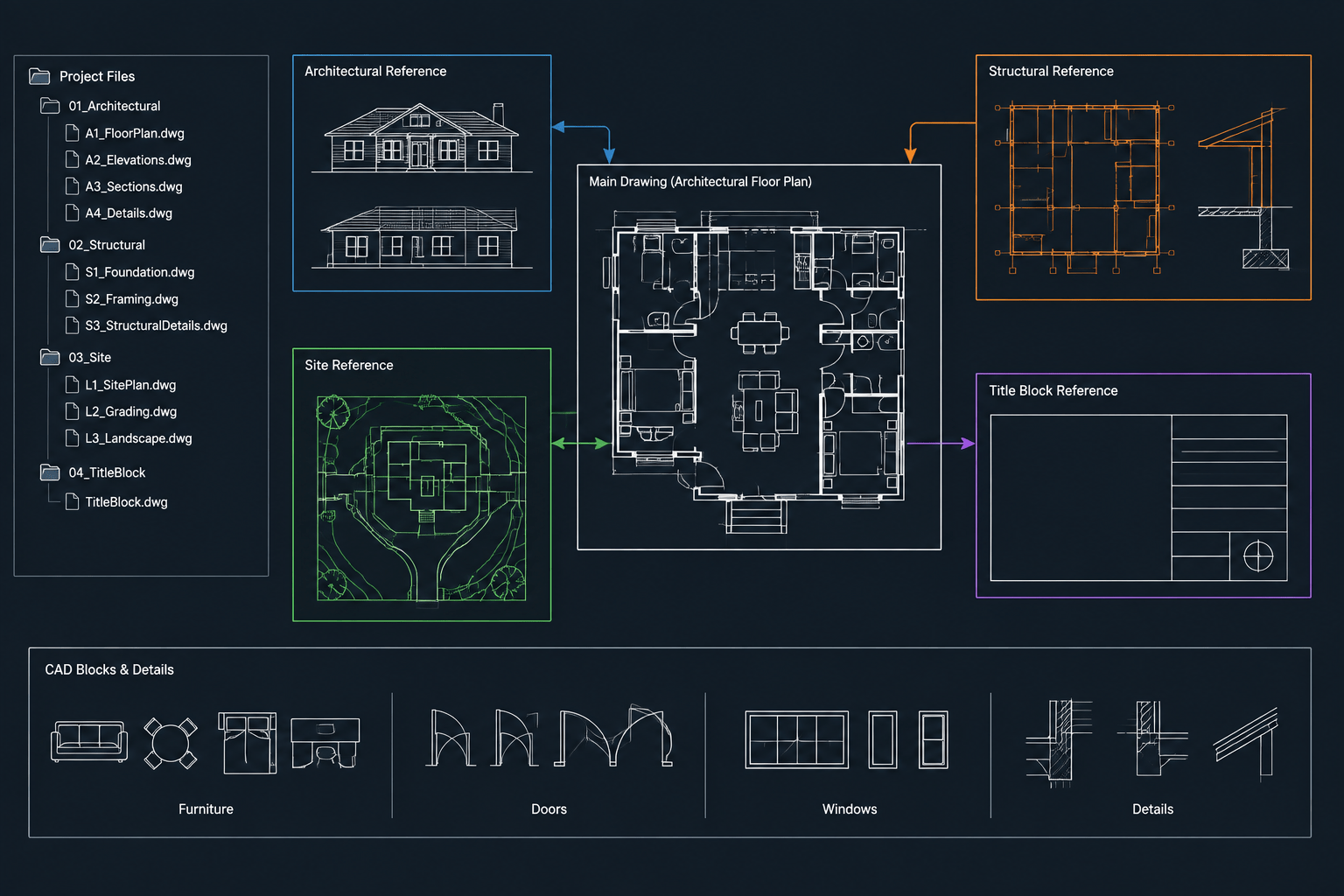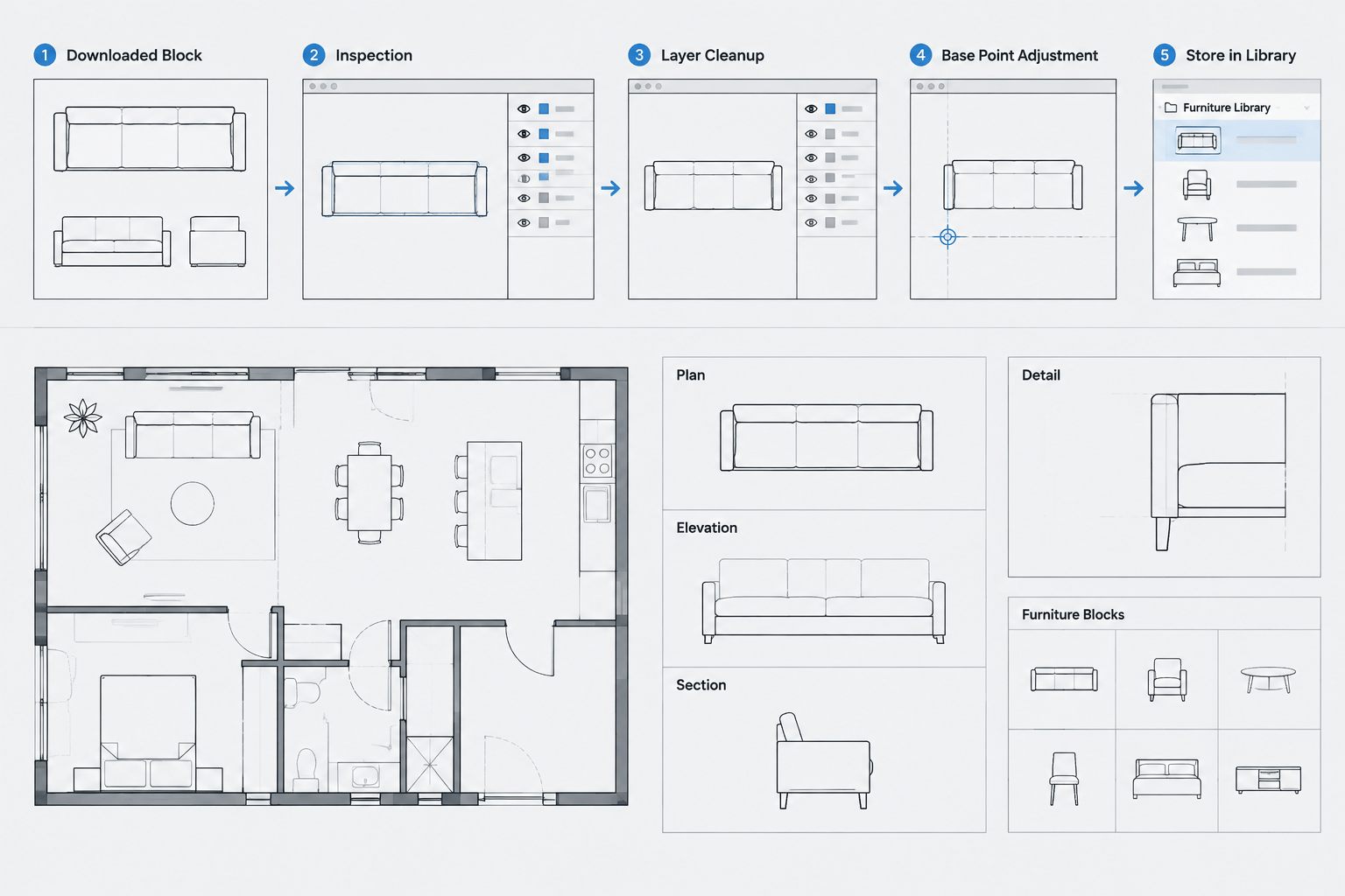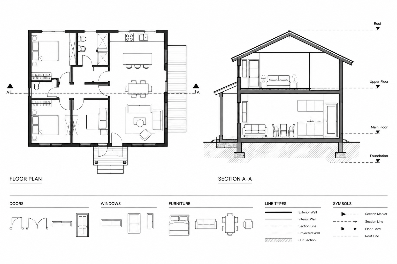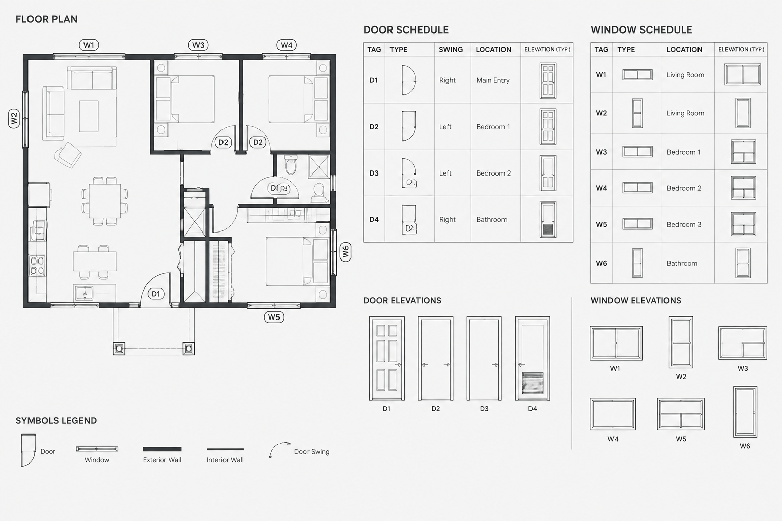
Architectural CAD block attributes turn ordinary block geometry into reusable drawing objects that can carry editable information. A door tag can display a mark, a room symbol can hold a room name, and an equipment symbol can store an identification code without requiring separate text objects.
Attributes are useful, but they need a deliberate structure. Poorly named tags, inconsistent prompts, duplicate information, and unsynchronized block instances can make a drawing harder to coordinate. The goal is not to attach data to every block. It is to use attributes where information belongs logically to a repeated object and where controlled editing will improve the drawing workflow.
What Is a CAD Block Attribute?
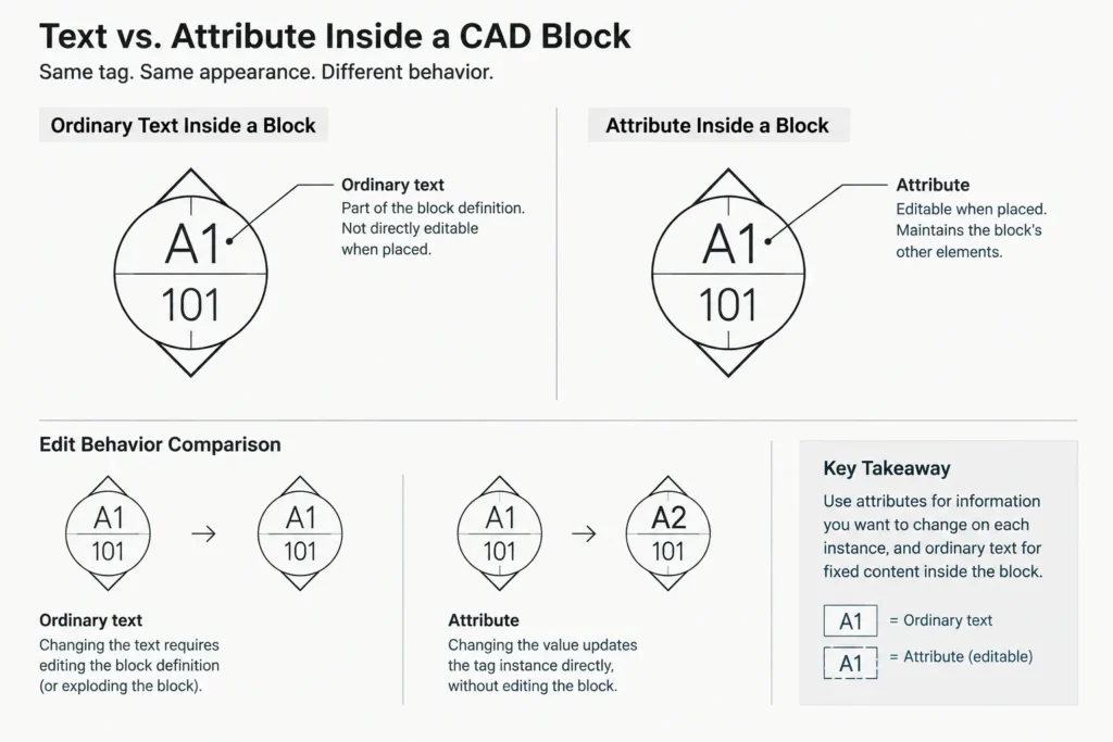
An attribute is a text-based data field included in a block definition. When the block is inserted, the user can enter or accept a value for that field. Each inserted block reference can then display different information while retaining the same underlying geometry.
This differs from normal text placed inside a block. Ordinary text remains the same in every instance unless the block definition is changed. An attribute value can vary from one block reference to another. For example, multiple door tags may share the same circle or polygon geometry while displaying different door marks.
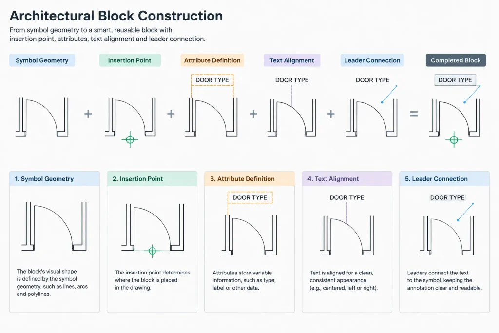
An attribute definition typically includes several coordinated parts:
- Tag: The internal identifier used by the drawing and data-management tools.
- Prompt: The instruction shown when a value is requested.
- Default value: Optional starting content for the attribute.
- Displayed value: The content visible in a particular block reference.
- Text properties: The layer, text style, justification, orientation, and other graphic settings.
The internal tag and the displayed value serve different purposes. A tag such as DOOR_MARK identifies the field, while the displayed value might be a project-specific mark.
Where Attributes Are Useful in Architectural Drawings
Attributes work best for repeated symbols whose graphic form stays consistent while their identification changes. Common applications include:
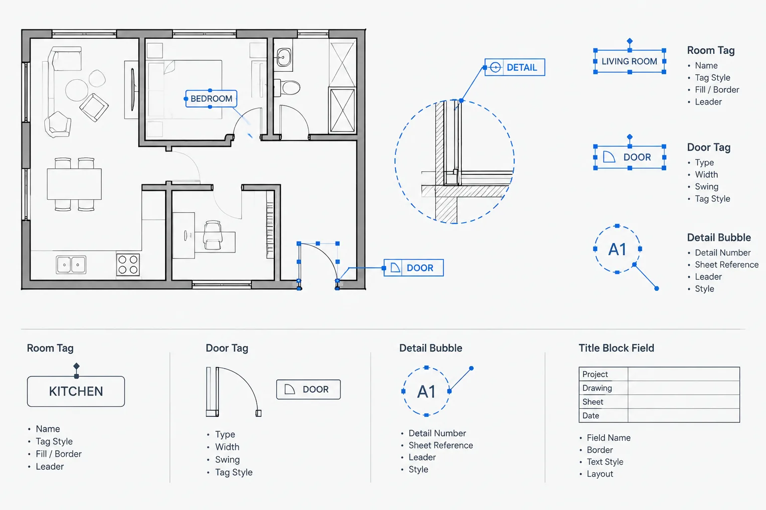
- Door, window, wall type, and finish tags
- Room and space identification symbols
- Equipment and plumbing fixture identifiers
- Detail, section, elevation, and drawing-reference bubbles
- Parking space or unit identification
- Furniture and equipment inventory codes
- Title block project and sheet information
- Keyed note symbols
Not every piece of annotation should become an attributed block. Long notes, general instructions, dimensions, and frequently reformatted paragraphs are usually better managed with their dedicated annotation tools. Attributes are most effective when each field has a clear relationship to the block.
Plan the Data Before Drawing the Block
Before creating attribute definitions, decide what the block needs to communicate. Separate visible drawing information from data that may only be needed for checking or extraction. A symbol may require one displayed identifier, while additional fields could create unnecessary editing and maintenance.
Use a short worksheet or block specification to define the fields:
| Planning question | Practical decision |
|---|---|
| What does the block identify? | Define the object or drawing reference represented by the symbol. |
| Which values vary by instance? | Create attributes only for information that needs to change. |
| Which information must be visible? | Distinguish plotted labels from internal project data. |
| How will the data be checked? | Determine whether users will review values manually or through data extraction. |
| Who maintains the block? | Assign responsibility for definition changes and library updates. |
This planning step prevents several attributes from being created for the same concept. It also reduces the temptation to use vague fields such as INFO or TEXT, which provide little guidance during editing.
Create Clear Attribute Definitions
Use stable internal tags
Choose attribute tags that describe the information rather than the current project value. Tags such as ROOM_NAME, TYPE_MARK, and SHEET_REFERENCE are easier to understand than generic or sequential names. Establish a consistent approach to capitalization and word separators across the block library.
Avoid casually renaming tags after blocks are already used in project files. The tag is part of the data structure, not merely a visible label. Changing it may complicate synchronization, extraction, or downstream checking.
Write prompts for the user
The prompt should tell a drafter what to enter. It can be more readable than the internal tag. For example, a tag may use EQUIPMENT_ID while the prompt reads Enter equipment identifier.
Prompts should distinguish similar fields clearly. If a block asks for a type, mark, reference, and description, each prompt should explain which value belongs where.
Control text appearance through standards
Set attribute text to use the project’s approved text styles, layers, and plotting hierarchy. Check justification carefully because longer and shorter values can expand in different directions. A centered identifier may suit a tag bubble, while a left-aligned description may be more appropriate in a title block.
Test values of different lengths before publishing the block. A sample value that fits does not prove that realistic project content will remain inside the symbol.
Build the Block Around a Logical Insertion Point
The insertion point should support predictable placement and editing. For a tag, it may align with the graphic center or a leader connection. For a title block, it may correspond to a sheet corner. For an equipment symbol, it should relate to a stable geometric feature rather than an arbitrary empty location.
Create the geometry and attribute definitions on intentional layers, verify their order, and then form the block. Attribute order matters because it can influence the sequence in which values are requested or presented for editing. Arrange fields according to the way a user logically completes the block, not merely the order in which they were created.
Test the Block Before Adding It to a Library
Insert several test instances into a clean drawing rather than evaluating only the original definition geometry. Enter different values and check the block at the intended annotation or model-space workflow.
A useful test should confirm that:
- The insertion point produces predictable placement.
- Prompts appear in a logical order.
- Default values do not create misleading finished information.
- Longer values remain readable and do not collide with the symbol.
- Text orientation and alignment are consistent.
- Attributes appear on the intended layers.
- The block behaves correctly when moved, copied, rotated, and mirrored according to office practice.
- Plotted text remains legible within the drawing hierarchy.
Mirroring deserves particular attention. A symbol may need to change orientation without producing backward annotation. Test the actual project workflow rather than assuming that geometry and text will respond identically.
Edit Definitions and Synchronize Existing Instances
Editing an attribute in one inserted block changes that instance’s value. Editing the block definition changes the structure shared by block references. These are separate operations and should not be confused.
If an attribute definition is added, removed, reordered, or reformatted, existing block references may need to be synchronized with the revised definition. In AutoCAD workflows, attribute-management and synchronization tools can update existing references, but the results should be reviewed. A synchronization operation should not be treated as a substitute for checking project-specific values.
Before making a library-wide change:
- Save or archive the current project file according to the project’s revision practice.
- Identify drawings and external references that use the block.
- Test the revised definition in a copy of a representative drawing.
- Confirm which existing values must remain unchanged.
- Review affected sheets after synchronization.
Be especially careful when replacing a block with another block that looks similar but uses different attribute tags. Matching geometry does not guarantee compatible data.
Use Attribute Data Carefully
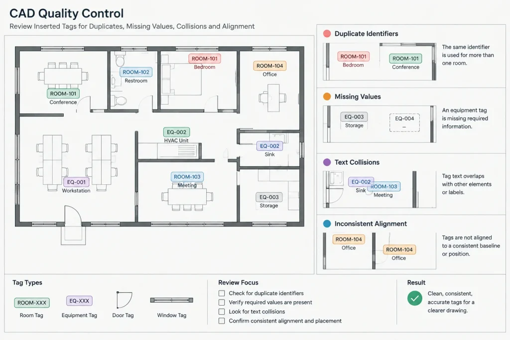
Attribute values can support schedules, inventories, and drawing reviews when the block definitions are consistent. Data extraction can help identify missing marks, duplicate identifiers, or inconsistent descriptions. However, extracted data is only as reliable as the inserted blocks and entered values.
Do not assume that an attributed door tag automatically coordinates with a door schedule, or that an equipment block represents a verified product. The project team must define the relationship between symbols, schedules, specifications, and consultant information. Visual similarity and matching labels are not proof of technical coordination.
Common Attribute Problems
- Duplicate tags within one block: Repeated internal identifiers can make fields difficult to distinguish and manage.
- Generic tag names: Tags such as VALUE provide little context during extraction or troubleshooting.
- Exploded attributed blocks: Exploding separates the information from the reusable block structure and can leave ordinary text behind.
- Unnecessary hidden data: Extra fields increase maintenance without improving the drawing.
- Manual text placed over a block: The symbol may look correct while its stored attribute value remains wrong.
- Uncontrolled library revisions: Similar blocks with different tags can fragment project data.
- Assuming defaults are verified values: Placeholder content may be mistaken for coordinated project information.
A Practical Office Workflow
Start with a small, documented set of attributed blocks for high-value applications such as tags, reference symbols, and title blocks. Give each block an identifiable owner or source, use consistent tag naming, and keep a test drawing that demonstrates intended behavior.
When a project needs a variation, first determine whether the existing block can support it without changing its data structure. If a new block is necessary, distinguish it clearly and document how its fields differ. At drawing milestones, review both visible labels and stored values. This combination of graphic checking and data checking makes architectural CAD block attributes more dependable without turning every symbol into an overly complex database object.