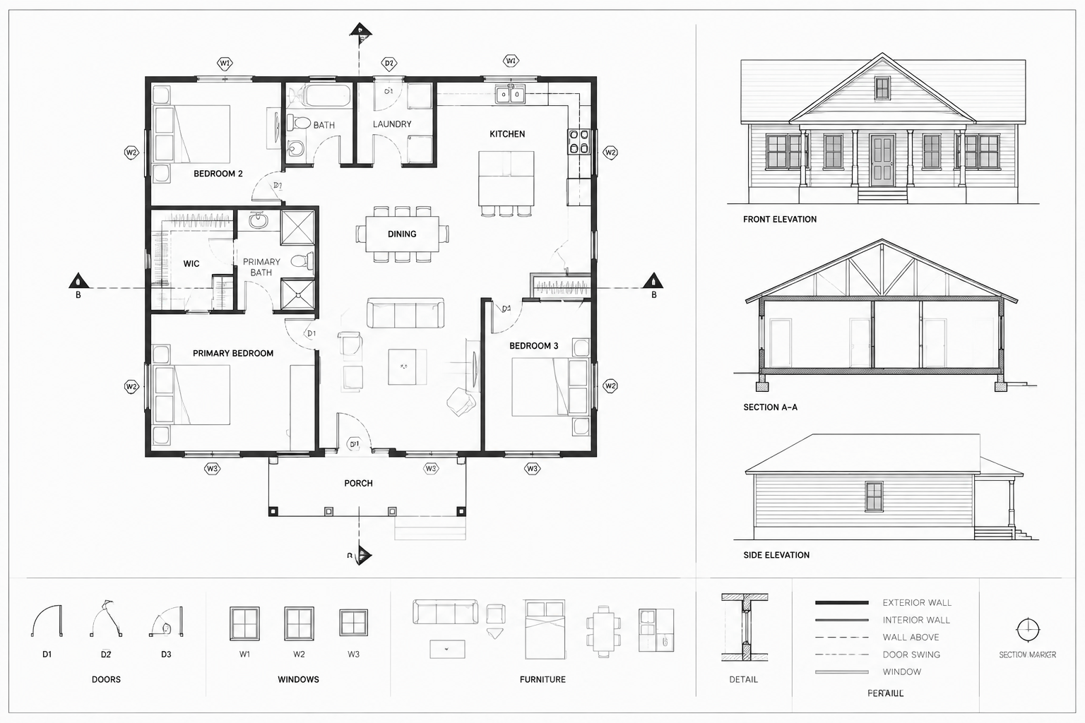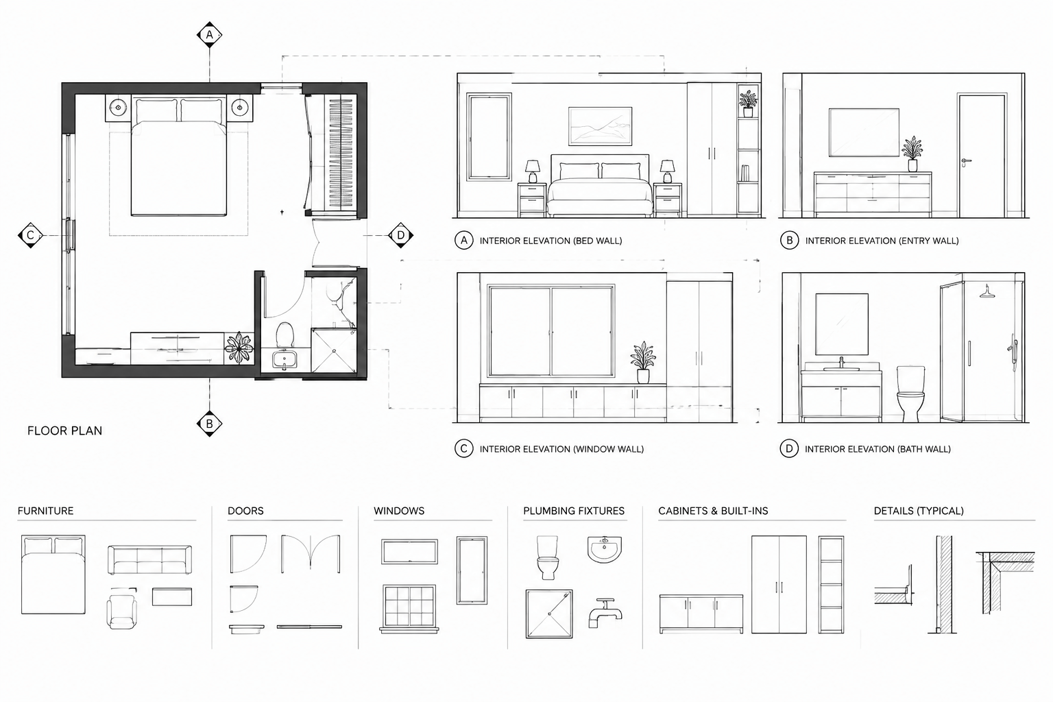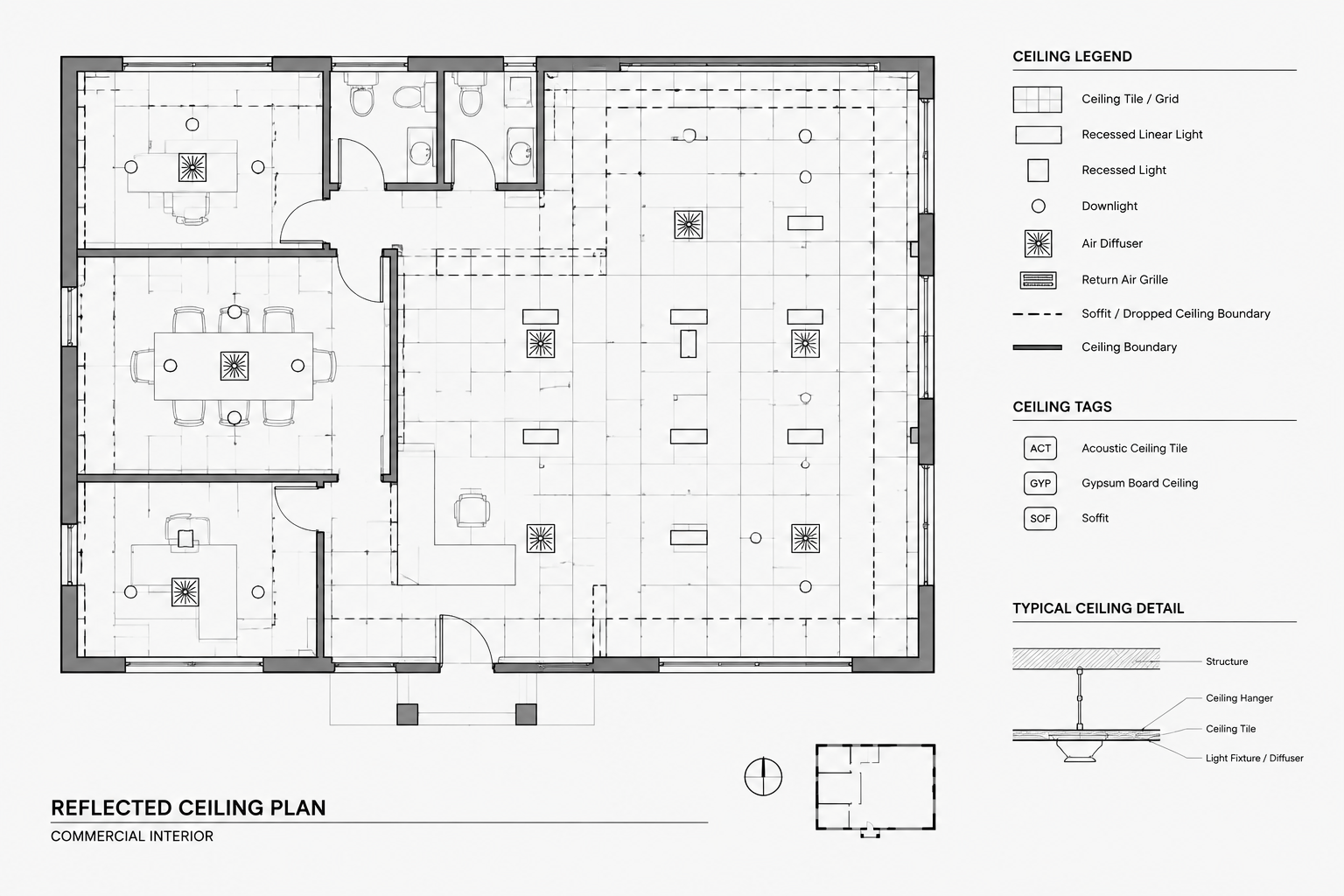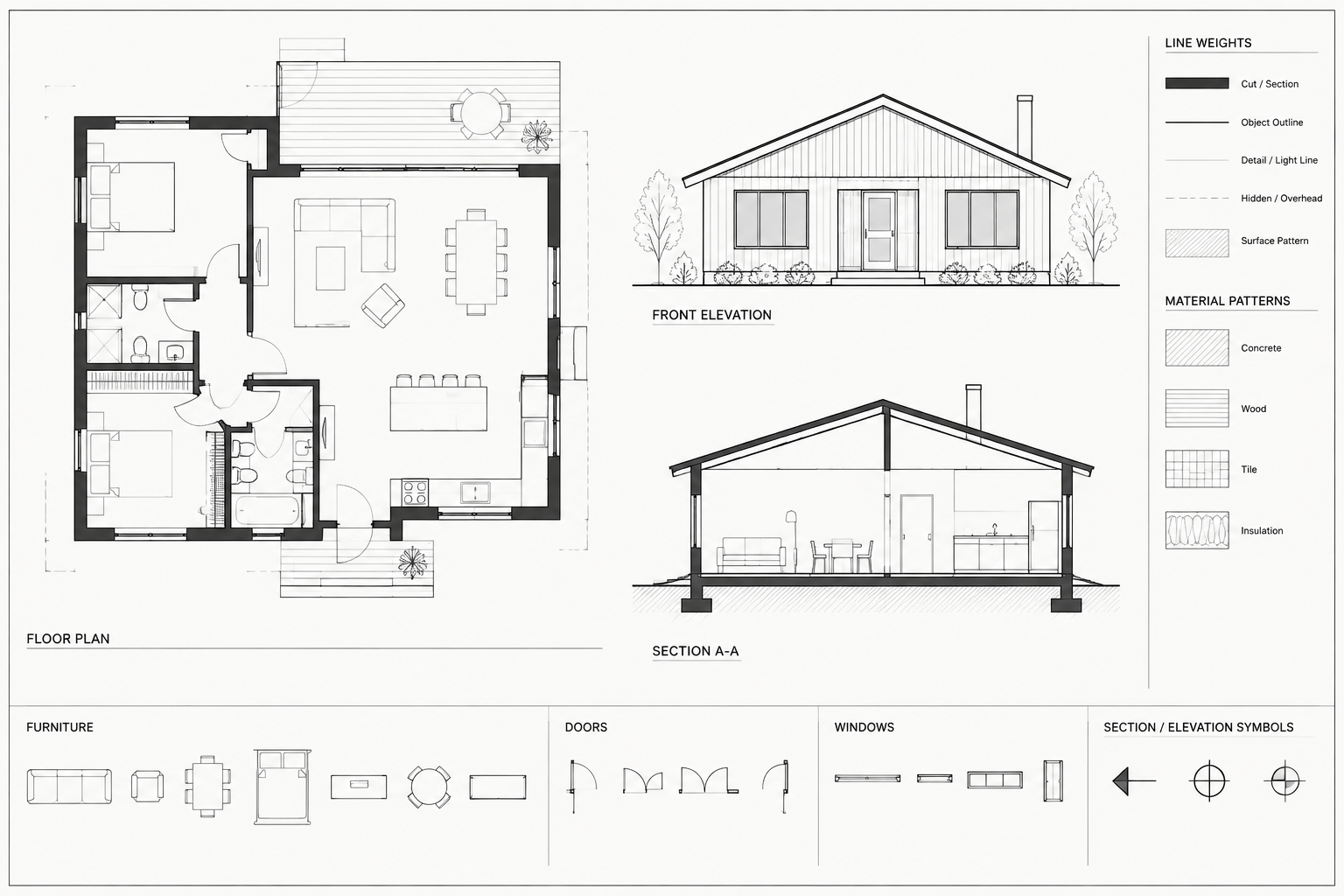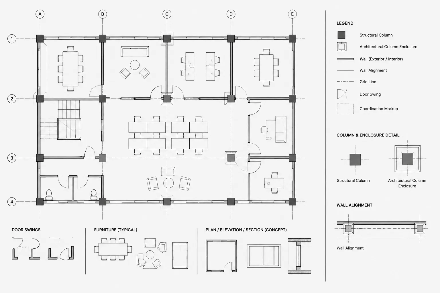
Coordinating structural columns in an architectural CAD plan is not simply a matter of placing column symbols over a floor plan. The architectural drawing must preserve the structural reference while clearly showing how walls, finishes, openings, furnishings, ceilings, and exterior assemblies respond to each support.
This guide presents a practical workflow for reviewing column locations without obscuring source information or assigning structural decisions to the architectural drawing. It also explains how to document discrepancies so they can be resolved rather than hidden within copied or adjusted geometry.
Structural columns influence far more than the structural plan. Their positions can affect wall alignment, door clearances, room layouts, finish transitions, ceilings, built-in casework, and exterior detailing. When column information is transferred into an architectural floor plan without a clear coordination method, small discrepancies can spread across multiple drawings.
The architect or drafter should not redesign structural elements or assume that a downloaded symbol represents the required construction. The goal is to reference the current structural information accurately, show its architectural consequences, and identify conflicts for resolution by the appropriate project team member.
Separate structural geometry from architectural enclosure
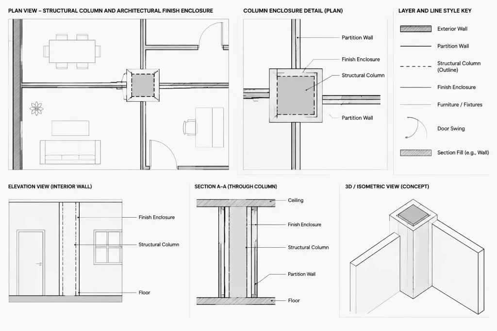
A column and its architectural enclosure are not necessarily the same shape. The structural element may be surrounded by fire protection, furring, finish material, a decorative cover, or a wall assembly. Treating the finished enclosure as if it were the structural column can make coordination difficult because the source geometry becomes unclear.
Maintain a visible distinction between:
- The structural column or support location received from the structural discipline.
- The architectural finish or enclosure surrounding it.
- Nearby walls, glazing, casework, and other elements designed around it.
- Annotations that identify a coordination issue rather than completed construction.
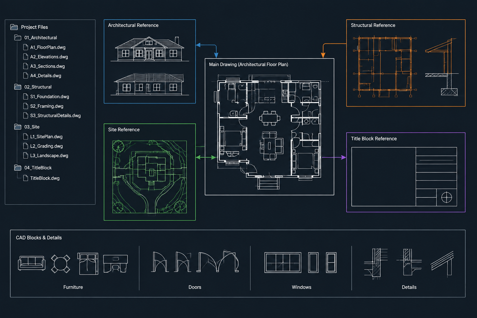
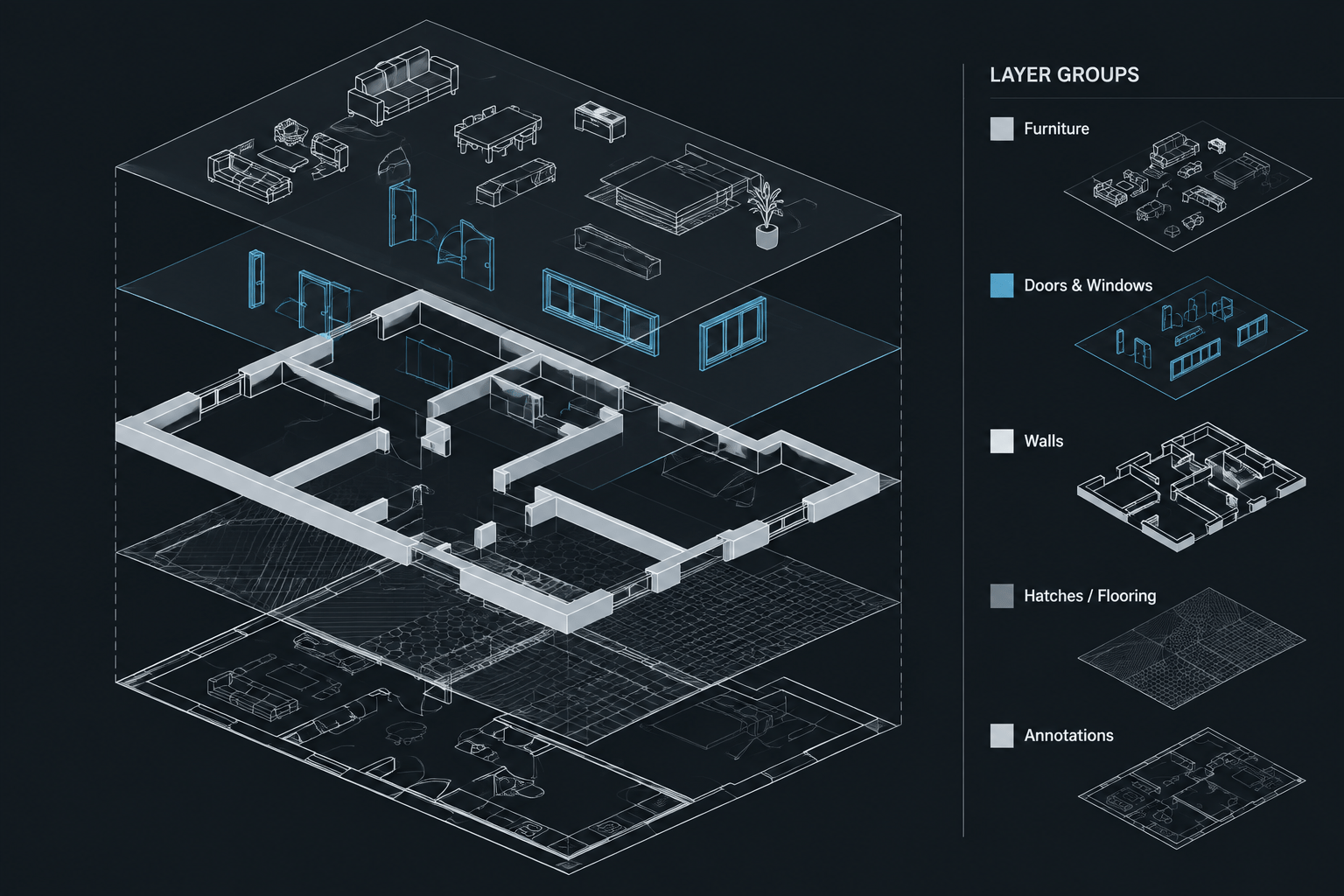
These components can be separated with layers, external references, or other project-approved drawing controls. The method matters less than preserving the ability to identify the structural source and the architectural response independently.
Start with a controlled structural reference
Use the current structural background whenever one is available. Attach or reference it according to the project’s established file structure rather than copying selected columns into the architectural plan without source information. Copied geometry can become outdated when the structural drawing changes.
Before checking individual columns, confirm that the architectural and structural files share the correct drawing units, project origin, orientation, and grid relationship. A file that appears visually aligned near one area may still contain a rotation, scale, or coordinate problem that becomes apparent elsewhere.
Confirm the coordination framework
- Compare corresponding grid lines or other agreed control points.
- Check that floor levels and plan areas represent the same portion of the building.
- Verify whether the structural reference represents the current design issue.
- Look for columns shown on one discipline’s plan but missing from the other.
- Confirm whether sloped, transferred, offset, or discontinuous supports require special review.
Do not force an apparent alignment by moving structural reference geometry within the architectural file. If the backgrounds disagree, record the discrepancy and resolve the underlying source or coordinate issue.
Build a repeatable column coordination workflow
1. Compare column centers with the project grids
Where columns are grid-related, compare their centers or other defined reference points with the architectural grid system. Do not assume that every column is centered on a grid intersection. Edge conditions, façade zones, existing construction, and project-specific structural layouts may create intentional offsets.
If an offset is important to the architectural layout, dimension it from a stable control reference rather than from furniture, finish lines, or other elements likely to change.
2. Review column size and orientation
A column symbol may be centered correctly but rotated incorrectly or represented with outdated dimensions. Compare the visible size, shape, and orientation with the current structural background. Avoid replacing an irregular or rectangular support with a generic square block merely to simplify the plan.
When structural sizes have not been finalized, use the project’s approved placeholder method and identify the unresolved condition. Do not invent a likely size.
3. Draw the architectural enclosure separately
Develop the enclosure around the referenced structure using the wall, finish, or partition information appropriate to the project. Consider how the enclosure meets adjacent walls and whether the finished faces should align with other surfaces.
At this stage, review corners and narrow residual spaces carefully. A column wrap that looks acceptable at a distant plan scale may create awkward finish strips, unusable recesses, or difficult construction interfaces when enlarged.
4. Test nearby openings and circulation
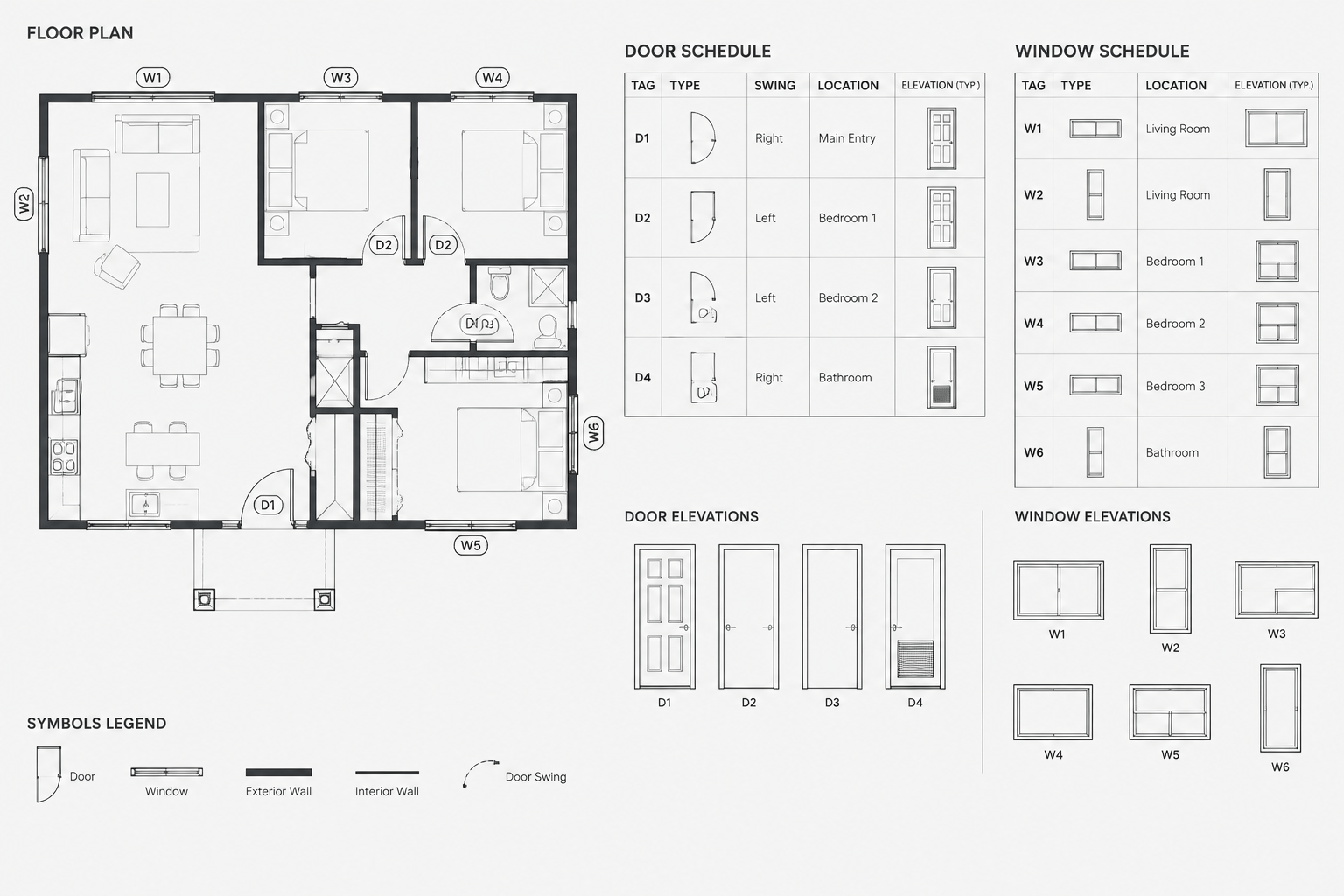
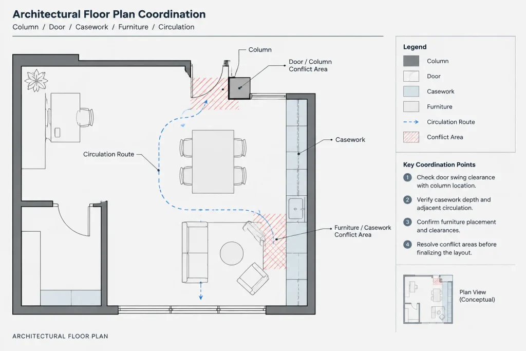
Columns near doors and openings deserve focused review. Check the actual door leaf, swing, frame zone, wall return, hardware side, and approach area shown by the architectural layout. A centerline-only review may miss a conflict between a finished column enclosure and the operational space around an opening.
Circulation and accessibility requirements depend on the project type, jurisdiction, and adopted criteria. Use verified project requirements rather than assuming that a familiar clearance applies universally.
5. Coordinate furniture, fixtures, and equipment
Column locations can affect seating arrangements, workstations, cabinets, counters, plumbing fixtures, and equipment access. Keep movable furniture visually distinct from fixed construction so that a layout adjustment is not mistaken for a structural solution.
Where a fixed item must fit between a wall and a column, coordinate the available finished space rather than measuring only to the structural face. Include the enclosure and other relevant finish build-ups represented in the architectural design.
6. Check overhead and vertical relationships
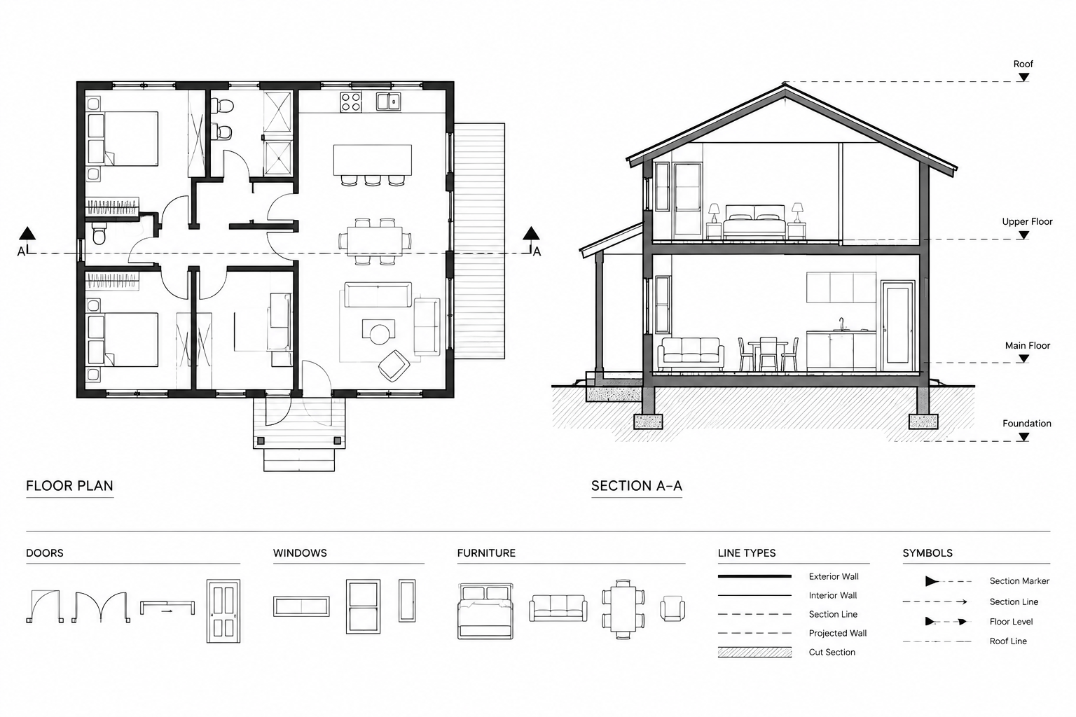
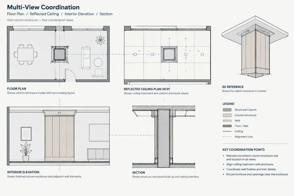
Do not limit column coordination to the floor plan. Compare the condition with reflected ceiling plans, sections, elevations, and relevant details. A column may align with the floor plan but conflict visually or physically with ceiling patterns, soffits, lighting layouts, façade modules, or interior finish bands.
Columns that change position, size, or enclosure between levels should receive particular attention. Review stacked plans together and use sections where a plan cannot communicate the vertical relationship clearly.
Plan elements that commonly conflict with columns
| Plan element | Coordination question | Useful drawing response |
|---|---|---|
| Partitions | Does the finished wall face align with or bypass the column enclosure? | Show structural and finish geometry separately and resolve small offsets. |
| Doors | Does the enclosure affect the frame, swing, wall return, or approach space? | Review the complete opening geometry at an enlarged scale. |
| Casework | Is the available space measured to the finished column face? | Coordinate cabinet extents, fillers, counters, and access needs. |
| Furniture | Does the column interrupt seating, work areas, or circulation? | Test realistic furniture footprints without treating movable items as fixed controls. |
| Ceilings | Does the vertical enclosure coordinate with ceiling edges and overhead elements? | Compare floor plans, reflected ceiling plans, and interior elevations. |
| Exterior walls | How does the column relate to glazing, cladding, insulation, and interior finish? | Develop the interface in plan, section, and detail as needed. |
Dimension and annotate without duplicating structural design
Architectural drawings should include the dimensions needed to construct and coordinate the architectural work, but unnecessary repetition can create conflicting instructions. If the structural drawings control column size and reinforcement, avoid restating that information as though the architectural drawing were the structural authority.
Architectural dimensions may instead locate finished faces, wall alignments, openings, room boundaries, and other design-critical relationships. When a structural location is essential to the architectural layout, coordinate the dimensioning responsibility with the project team.
Use notes or issue markers for unresolved conditions, but do not leave informal comments scattered across plotted sheets. Keep working annotations on non-plotting coordination layers or in the project’s issue-tracking process until they are resolved.
Special considerations for existing buildings
Existing columns may not match record drawings, especially where finishes conceal their actual shape. Distinguish field-verified information from record information and design assumptions. If the concealed condition is unknown, show it according to the project’s documentation convention rather than presenting an assumed outline as verified.
Renovation plans should also distinguish existing structural construction from new architectural enclosures and demolition work. Removing finishes around a column does not imply that the structural element itself is being altered.
Column coordination quality-control checklist
- The structural reference is current and visibly identifiable.
- Units, origin, orientation, levels, and grids have been checked.
- Column centers, sizes, shapes, and orientations match the available source information.
- Structural geometry is separate from architectural finishes and enclosures.
- Nearby doors, walls, glazing, casework, fixtures, and furniture have been reviewed.
- Overhead conditions and vertical continuity have been checked on related drawings.
- Architectural dimensions refer to clear, intentional control points.
- Unresolved discrepancies are documented rather than hidden by moving geometry.
- Existing conditions and assumptions are clearly distinguished.
- Plans, sections, elevations, and details show the same coordinated design intent.
Keep the coordination record readable
A well-coordinated floor plan does not need excessive graphics. It needs reliable source references, clear layer separation, disciplined annotation, and consistent relationships across drawing types. The most useful CAD file allows another team member to determine what came from the structural background, what was added architecturally, and what still requires a decision.
By checking columns as part of a broader spatial and drawing-coordination workflow, drafters can catch conflicts before they become embedded in wall layouts, finish plans, reflected ceiling plans, and construction details.
Turn detected conflicts into clear coordination questions
Finding a conflict is only part of the coordination process. The issue should be described in a way that allows the responsible team member to understand the location, affected elements, source references, and decision required. A useful coordination note identifies the condition without prescribing an unsupported structural or code solution.
For example, a drafter can state that a finished column enclosure overlaps a door frame zone or interrupts a planned wall alignment. The team can then determine whether the architectural layout, enclosure design, opening, or structural information should change.
Information to include in a coordination record
- Location: Identify the applicable plan area, grid relationship, room, or other stable reference.
- Source: Record which structural background or issued information was reviewed.
- Conflict: Describe the affected architectural elements and the visible discrepancy.
- Drawing impact: Note whether plans, ceilings, elevations, sections, or details may require revision.
- Status: Distinguish an open question from an approved response or completed drawing update.
Review the architectural consequences after a column changes
A revised column location or enclosure can affect more than the immediate plan area. After incorporating approved information, review dependent geometry and annotations rather than treating the column edit as an isolated task.
Check wall joins, room boundaries, door relationships, finish extents, casework, furniture, ceiling coordination, section markers, detail references, dimensions, and labels associated with the condition. This follow-through helps prevent the plan from showing updated geometry while related views continue to communicate an earlier arrangement.
Use visual hierarchy to support coordination
The structural reference, architectural construction, and temporary coordination graphics should remain visually distinguishable in the working file. Linework does not need to be visually dominant to remain traceable. The goal is to make the architectural plan readable while allowing reviewers to isolate the structural source when investigating a discrepancy.
Before issuing the drawing, confirm that temporary highlights, informal comments, and superseded comparison geometry have been removed from plotted views or retained only through the project’s approved coordination process.
Frequently asked questions
Should structural columns be copied into the architectural floor plan?
A controlled structural reference is generally easier to track than detached copied geometry. If project procedures require copied elements, their source and update responsibility should remain clear so outdated column information is not mistaken for current design data.
Should the architectural plan show the structural column or its finished enclosure?
The drawing may need to communicate both, but they should remain distinguishable. The structural geometry establishes the referenced support condition, while the architectural enclosure communicates finishes, furring, wall interfaces, or other architectural work around it.
What should a drafter do when the structural and architectural grids do not align?
Do not move the structural reference merely to make the files appear aligned. Check the shared coordinate framework, orientation, units, origin, and source issue. If the discrepancy remains, document it for project-team resolution.
How should a column conflict near a door be reviewed?
Review more than the door centerline or opening width. Consider the frame, leaf, swing, wall return, hardware relationship, finished column enclosure, and the project-specific approach or circulation criteria.
Who determines whether a structural column can be moved?
The architectural drafter should identify and communicate the conflict rather than independently relocating the support. Any structural change must be evaluated and authorized by the appropriate project professionals.
How can column revisions be checked across the drawing set?
Trace the affected condition through floor plans, reflected ceiling plans, elevations, sections, details, dimensions, and room-related layouts. Update dependent views only after the revised information has been confirmed through the project’s coordination process.