Graphic scale bars in architectural CAD are most dependable when they are managed as view-specific annotations rather than decorative sheet elements. Their geometry, labels, unit system, viewport relationship, and exported appearance must remain coordinated throughout drafting and revisions.
This guide explains how to choose a placement method, build inspectable CAD blocks, associate each bar with the correct view, and perform practical quality-control checks before a sheet is issued. Written dimensions and verified project information should still remain authoritative.
A graphic scale bar provides a visual relationship between a drawing and real-world distance. Unlike a written scale note, it can remain useful when a sheet is proportionally enlarged or reduced because the bar changes size with the drawing. However, that advantage only applies when the scale bar was created correctly and exported with the view it represents.
In architectural CAD drawings, scale-bar errors usually come from placing the wrong block, mixing model-space and paper-space methods, changing a viewport scale without updating its annotation, or copying a bar between details that use different scales. A reliable workflow treats the graphic scale as view-specific information rather than generic sheet decoration.
What a Graphic Scale Bar Communicates
A graphic scale bar is divided into labeled segments representing real dimensions. A reader can compare those segments with drawing geometry, even if the printed sheet no longer matches its original physical size.
This makes a scale bar different from a written statement such as “scale as noted.” Written scale information describes the intended plot relationship, while a graphic bar provides a visible measuring reference. Many drawing sets use both because they serve related but different purposes.
A scale bar does not guarantee that a print or PDF is accurate. Export settings, printer scaling, page fitting, image conversion, and screenshot capture can distort a drawing. It also should not replace written dimensions. Dimensions, notes, and verified project information remain the primary sources for construction and coordination.
Decide Whether the Bar Belongs to a Sheet or a View
The most important setup decision is whether the entire sheet uses one drawing scale or contains multiple scaled views.
Single-scale sheets
If every relevant viewport on a sheet uses the same scale, one clearly positioned scale bar may be sufficient. It should still be visually associated with the drawing area and should not imply that unscaled diagrams, schedules, or photographs use the same scale.
Multiple-scale sheets
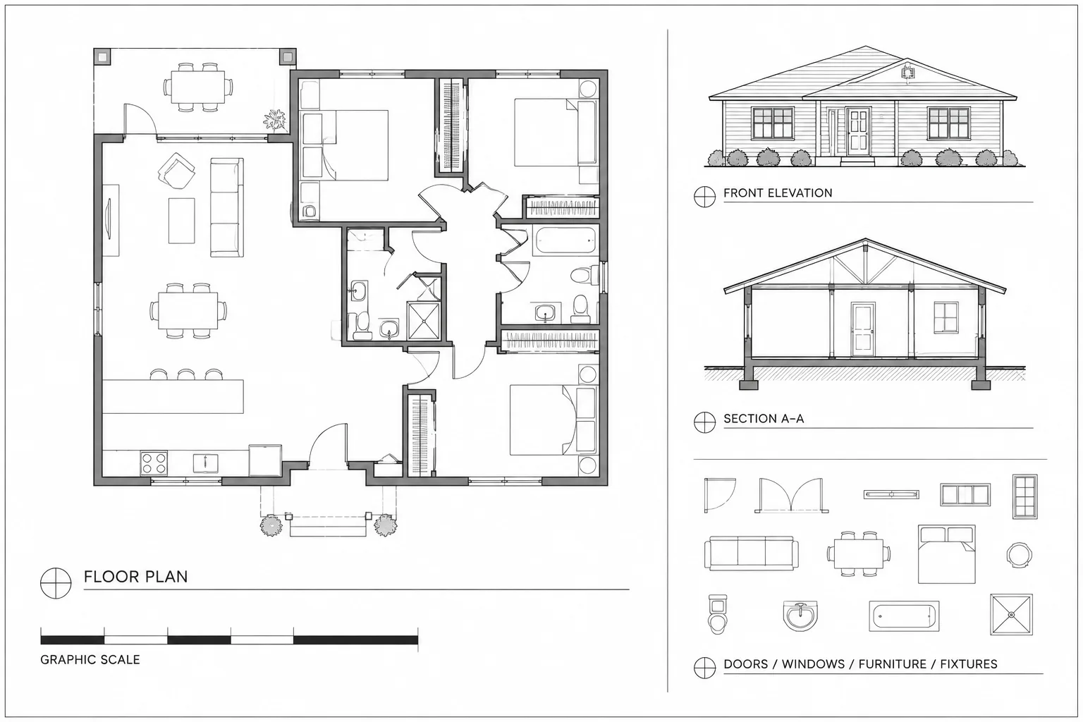
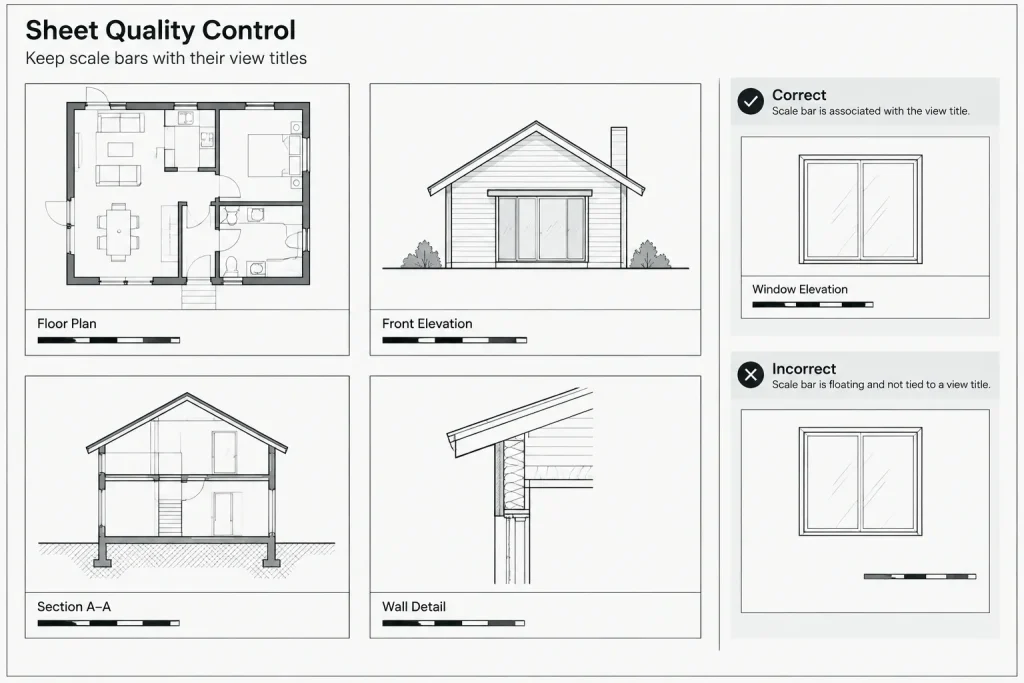
Plans, elevations, sections, and details are often combined at different scales. In this situation, each scale bar should be attached visually and logically to the view it represents. Placing one generic bar near the title block can create ambiguity.
For a multi-view sheet, coordinate the scale bar with the view title. The view title, written scale, detail reference, and graphic scale should tell the same story. If a view is marked not to scale, it should not receive a bar that suggests measurable accuracy.
Paper Space and Model Space Workflows
Graphic scale bars can be managed in either paper space or model space, but the method must be deliberate and consistent.
Paper-space scale bars
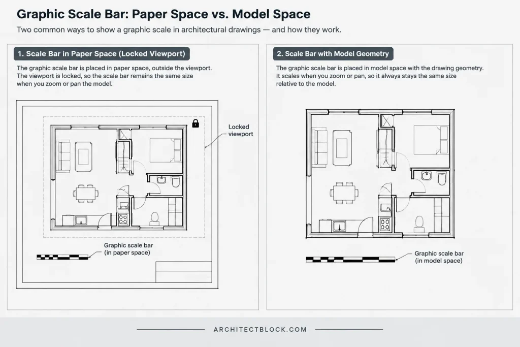
A paper-space bar is drawn at its intended plotted size and configured for a specific viewport scale. This approach gives the drafter direct control over its printed text height, lineweight, and position on the sheet.
The main risk is that the bar is not automatically tied to the viewport. If someone changes the viewport scale, the paper-space bar may become incorrect while still looking visually acceptable. A scale change therefore requires a coordinated update to the view title and scale bar.
Model-space scale bars
A model-space bar represents actual model dimensions. It appears through the viewport along with the architectural geometry. Depending on the office workflow, the text and symbols may be annotative or may be sized for the intended plotting scale.
This method can keep the bar geometrically connected to the model, but it requires careful annotation management. The bar must appear at a suitable plotted size and should not become visible in unrelated viewports.
Choose one controlled method
Neither location is universally correct. Paper space is often convenient for sheet-specific graphics, while model space can be useful when the bar is considered part of a defined drawing view. Problems arise when both methods are mixed without clear ownership.
How to Build a Reliable Scale-Bar Block
A reusable block should be simple enough to inspect. Decorative or overly complex graphics make it harder to determine whether the bar is accurate.
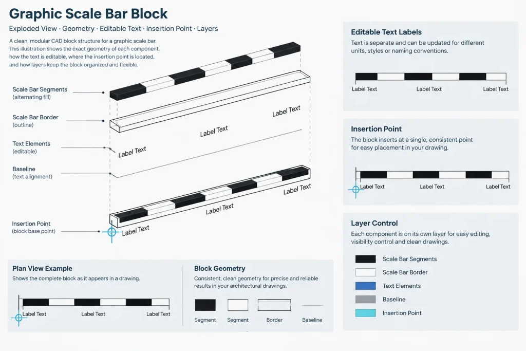
- Use exact segment geometry: Construct the bar from known drawing lengths rather than scaling an image by eye.
- Set a logical insertion point: A corner or baseline endpoint makes alignment with view titles and sheet guides easier.
- Keep text editable: Labels must match the represented units and segment lengths.
- Use controlled object properties: Assign layers and ByLayer or ByBlock properties according to the project’s CAD standard.
- Avoid unnecessary nesting: Deeply nested blocks make edits and troubleshooting more difficult.
- Separate incompatible unit systems: Do not rely on a label change alone to convert a bar between measurement systems.
A dynamic block may offer visibility states or controlled configurations for commonly used scales. If dynamic behavior is used, limit the available choices and test every state. A stretch action that changes the geometry without updating the labels can produce a convincing but inaccurate result.
A Step-by-Step Placement Workflow
- Confirm the viewport first. Establish the view boundary, crop, orientation, and intended scale before adding the bar.
- Lock the viewport. Locking helps prevent accidental zoom changes after annotation is coordinated.
- Identify the drawing units. Confirm how model units correspond to project units before selecting or creating the scale bar.
- Insert the correct bar. Use a verified library block intended for the selected unit system and view scale.
- Coordinate the labels. Check that every written value corresponds to the actual segment geometry.
- Place it near the view title. The association should be clear without covering dimensions, notes, or drawing geometry.
- Plot a test output. Review the PDF or print rather than relying only on the CAD display.
- Measure the exported result. Compare the full bar length and internal divisions with known geometry in the same view.
When measuring a PDF, first verify that the document has not been resized or printed using a fit-to-page option. PDF measurement tools can assist with checking, but their calibration and page handling must also be verified.
Coordinating Bars with View Titles and Viewports
A scale bar should be treated as one component of a coordinated view-annotation group. That group may include a view title, view number, written scale, reference information, and graphic scale.
If the viewport moves, the annotation should move with it. If the viewport scale changes, the written and graphic scales must both be reviewed. CAD groups can help with sheet arrangement, while blocks can standardize the graphic appearance. Neither method automatically validates the represented scale.
On crowded detail sheets, establish a consistent location relative to each view title. Consistency makes missing or mismatched bars easier to notice during review. Avoid allowing a bar to float between adjacent details, where its ownership may be unclear.
Common Scale-Bar Errors
| Error | Why It Happens | Recommended Check |
|---|---|---|
| Bar does not match the written scale | The viewport changed after annotation was placed | Compare the viewport properties, view title, and bar geometry |
| Labels are correct but segments are wrong | A block was stretched or non-uniformly scaled | Inspect block scale factors and measure the source geometry |
| Bar looks correct in CAD but not in PDF | The page or viewport was resized during output | Review page setup and exported sheet size |
| One bar appears to apply to several views | Placement is too far from its intended view | Move it into the view-title zone |
| Text is unreadable after reduction | The plotted annotation size was not tested | Review both the intended sheet and common reduced output |
| Wrong unit system is shown | A block was copied from another project or sheet | Verify labels, geometry, and model units independently |
Quality Control Before Issuing
Do not verify a graphic scale bar only by comparing it with another scale bar. Both may have originated from the same incorrect block. Instead, compare the bar with known model geometry, the actual viewport scale, and the written view scale.
- Check for non-uniform block scaling.
- Confirm that bar labels match the project’s unit conventions.
- Verify that the viewport is locked at the intended scale.
- Look for duplicate or overlapping bars left from copied layouts.
- Confirm that unscaled views are not presented as measurable drawings.
- Review lineweight and text readability in the exported PDF.
- Test reduced sheets if reduced printing is expected.
Graphic scale bars are small drawing elements with a significant coordination role. When they are based on exact geometry, clearly assigned to a view, and checked after plotting, they help readers understand scaled architectural information without creating false confidence. The safest workflow combines a verified bar, a coordinated written scale, locked viewports, and dimensions that remain authoritative for project use.
Make Scale Verification Part of Revision Control
A graphic scale can be correct when first placed and become incorrect after an otherwise routine drawing change. Viewport rescaling, copied layouts, block replacement, unit changes, and sheet reorganization should therefore trigger another review.
A useful workflow assigns ownership of the bar to the same person or process responsible for the view title and viewport. This reduces the chance that one annotation is updated while another is overlooked. Reviewers should evaluate the viewport, written scale, bar geometry, and exported sheet as a coordinated set.
Use a Verification Hierarchy
Start with known model geometry and confirmed drawing units. Then inspect the viewport settings, compare the written scale, measure the scale-bar segments, and review the final output. This sequence is more reliable than judging the bar by its appearance or comparing it only with another library block.
Control the CAD Library Source
Store approved scale-bar blocks with clear names that distinguish their unit system and intended workflow. Limit informal copies embedded in unrelated project files, because visually similar blocks may contain altered geometry, text, layers, or scale factors.
When a block is revised, inspect existing sheet instances rather than assuming they have inherited the correction. Nested blocks, local redefinitions, and copied layouts can preserve older content.
Review the Deliverable, Not Just the CAD File
The final review should include the issued output because page handling can affect the apparent relationship between the drawing and its bar. Check that the bar remains legible, belongs unmistakably to the intended view, and was exported with that view. A bar can help readers assess a proportionally resized sheet, but it cannot validate distorted or independently edited content.
Frequently Asked Questions
Should every architectural view have a graphic scale bar?
Not necessarily. The decision depends on the drawing type, sheet organization, project conventions, and whether a bar would communicate useful measurable information. A view identified as not to scale should not be paired with a graphic that implies otherwise.
Can one scale bar serve several viewports?
Only when its association is unambiguous and the applicable views use the same verified scale. On sheets containing different view scales, placing a bar with each relevant view title is generally clearer.
Is a paper-space scale bar better than a model-space bar?
Neither method is automatically better. Paper space provides direct control over sheet graphics, while model space can keep the bar associated with drawing geometry. Reliability comes from using a consistent method and verifying it after viewport or annotation changes.
Why can a scale bar look correct but still be wrong?
Its labels may have been edited without changing its geometry, the block may have been stretched, or the viewport may have changed after placement. Output scaling can also alter the delivered sheet. Visual appearance alone is not a sufficient check.
Does a graphic scale bar replace written dimensions?
No. A scale bar is a visual reference for understanding drawing scale. It should not override written dimensions, notes, or verified project information.
When should the scale bar be checked again?
Review it after changes to the viewport, view title, sheet arrangement, unit workflow, block definition, page setup, or export process. It should also be checked as part of the final sheet review.