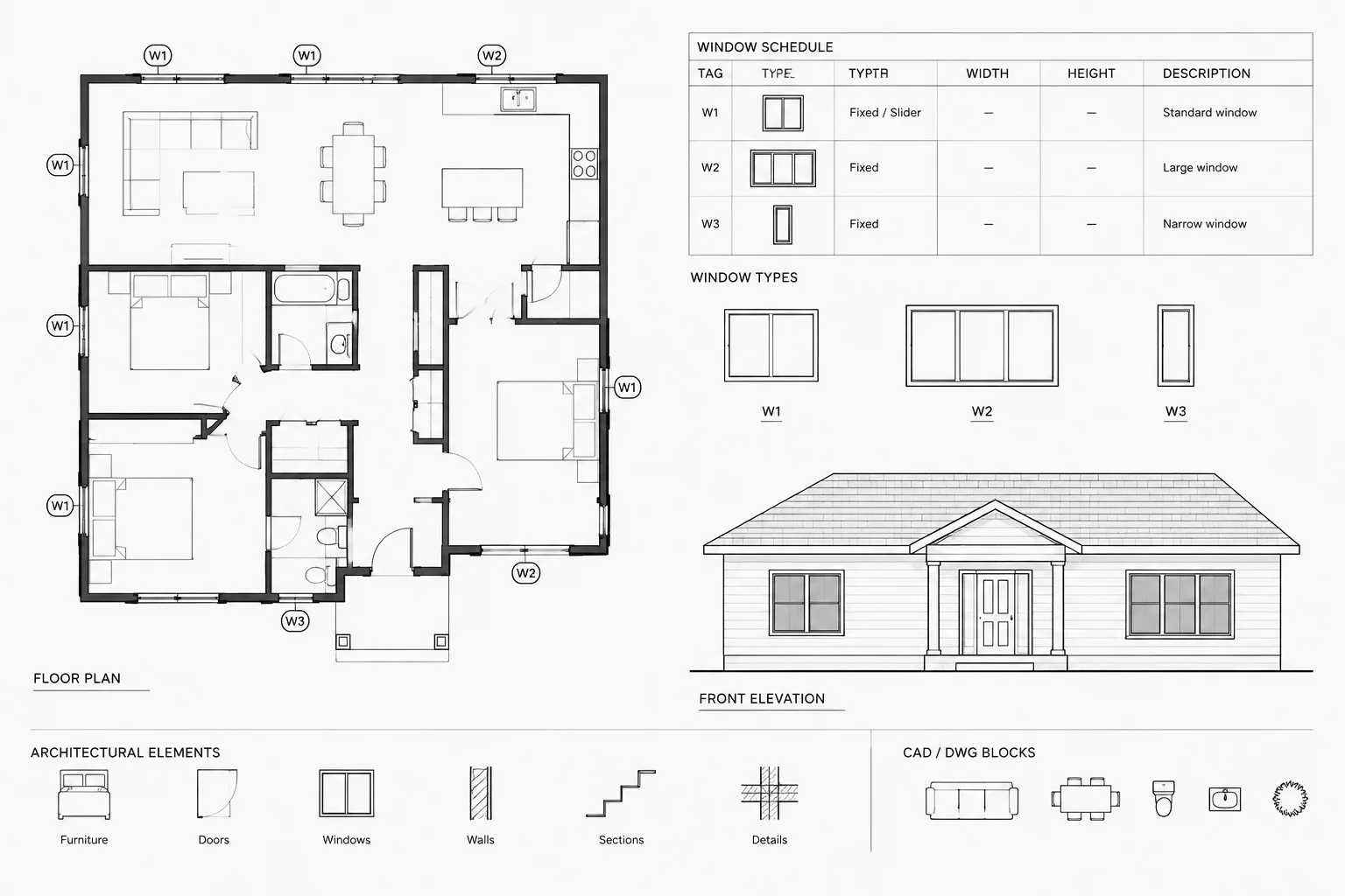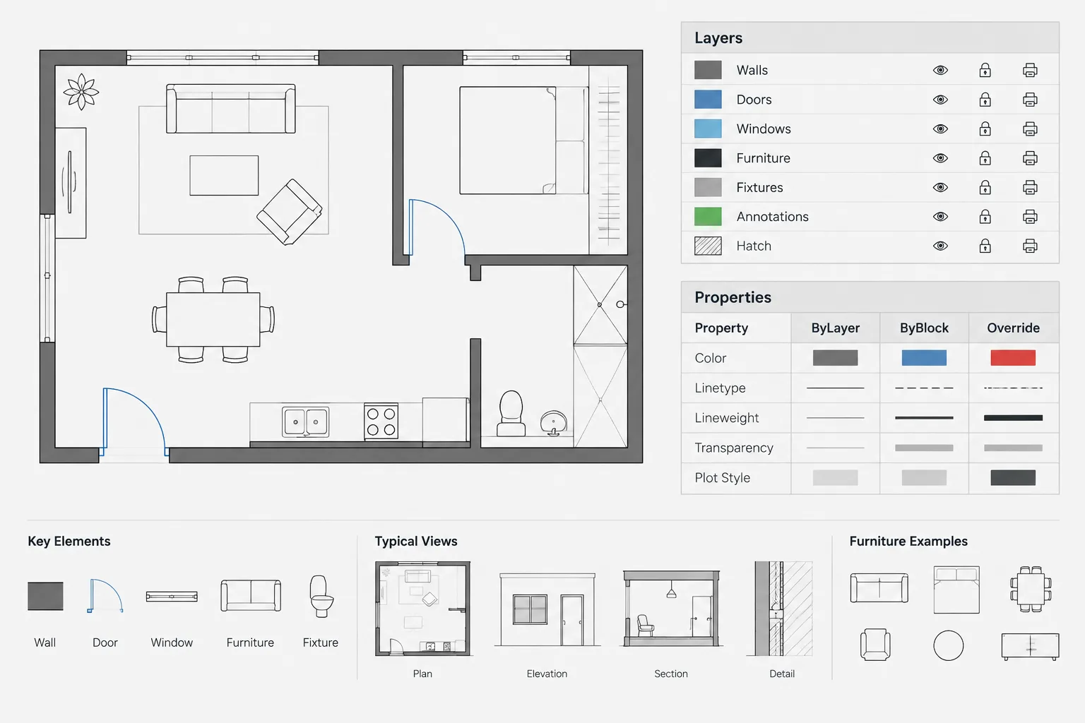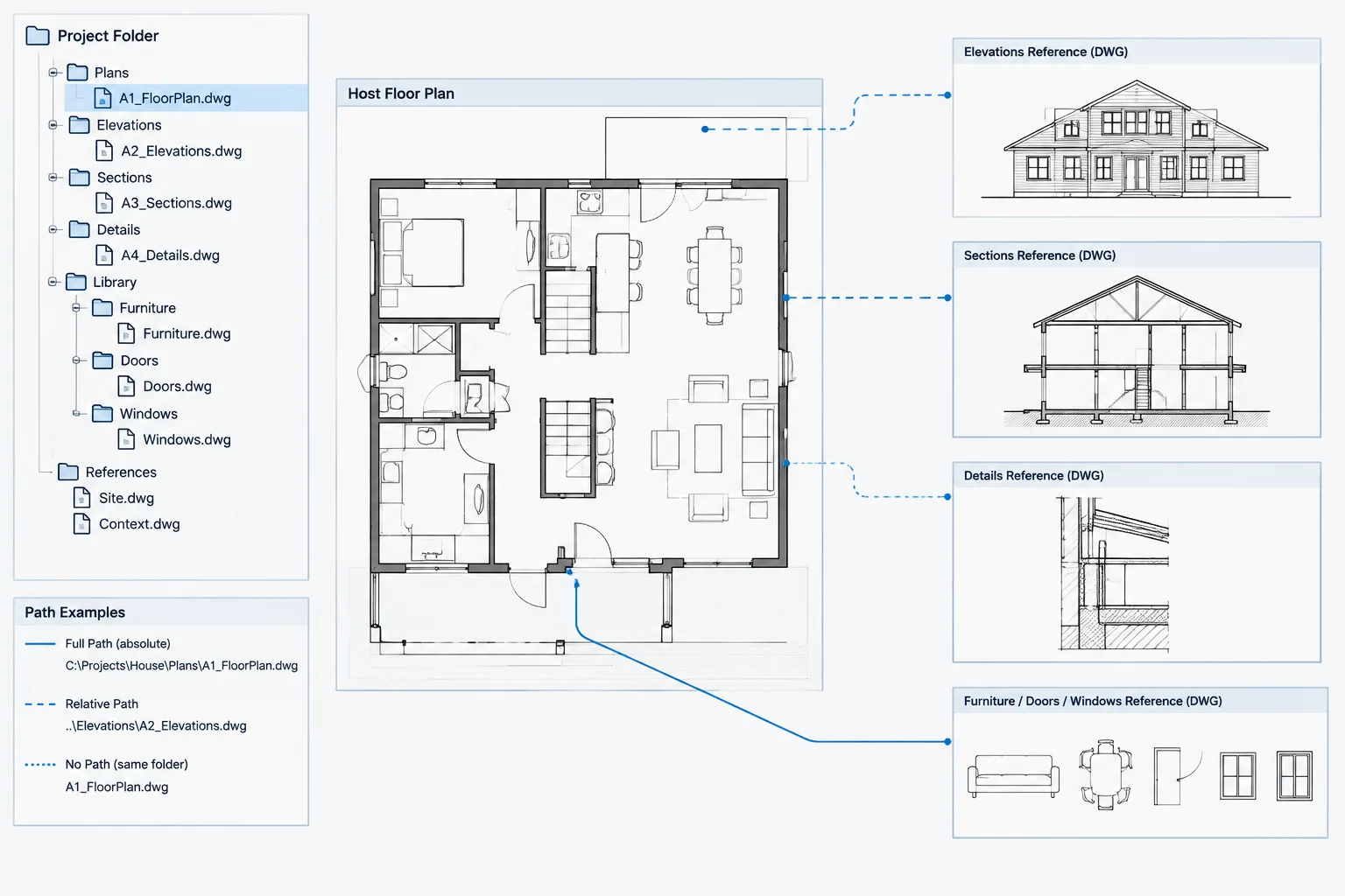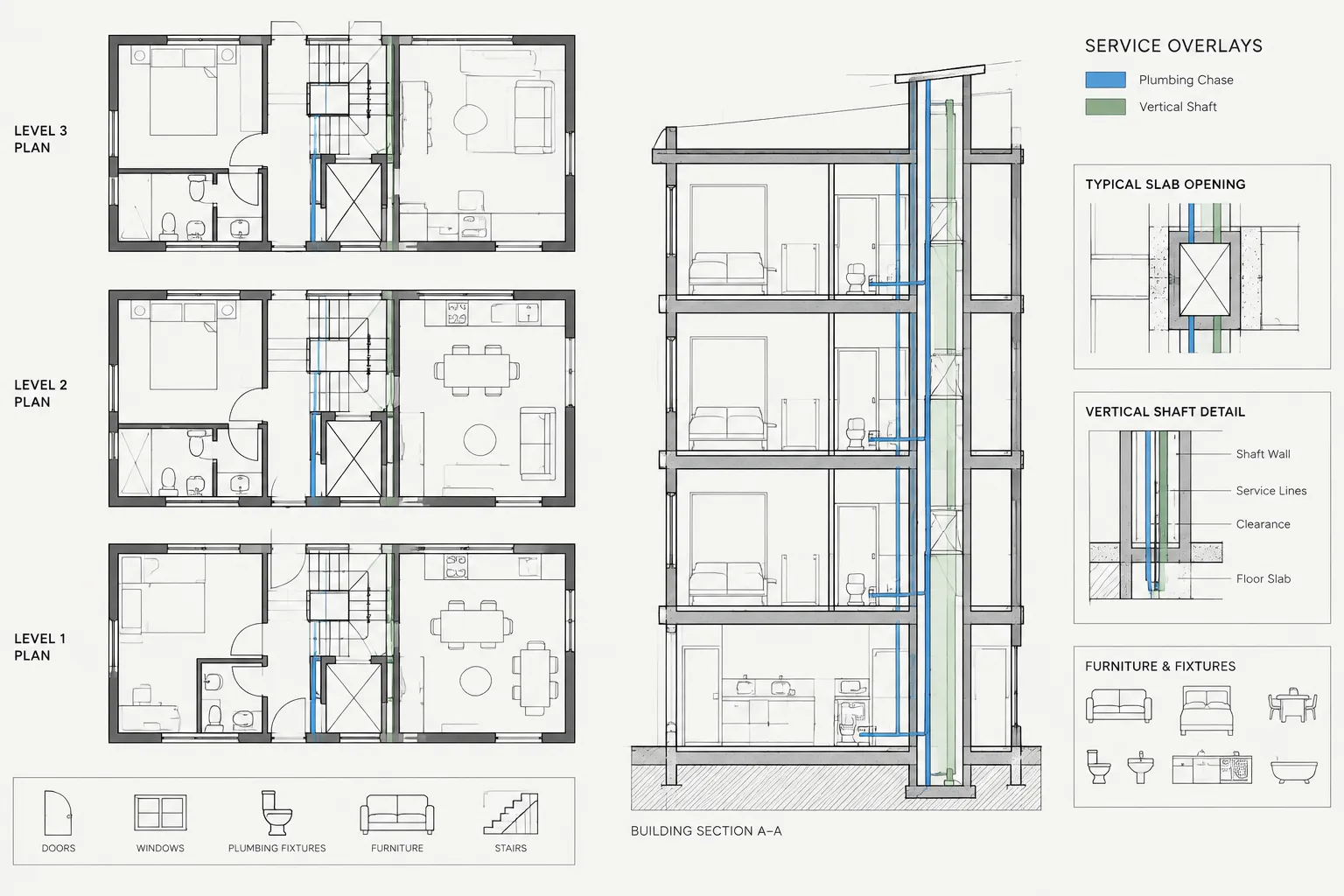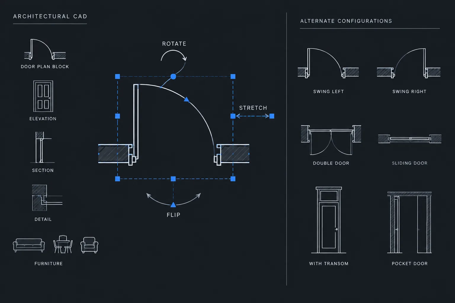
Dynamic blocks are most effective when they simplify a repeated drafting decision without making the drawing harder to interpret. Their value comes from controlled variation: users can adjust an approved property while the block preserves its intended geometry, insertion logic, annotation behavior, and identity.
This guide explains how to decide whether a component should be dynamic, choose appropriate controls, build behaviors incrementally, and test the resulting block as a reusable architectural library asset. It also identifies situations in which separate conventional blocks provide a clearer and more maintainable solution.
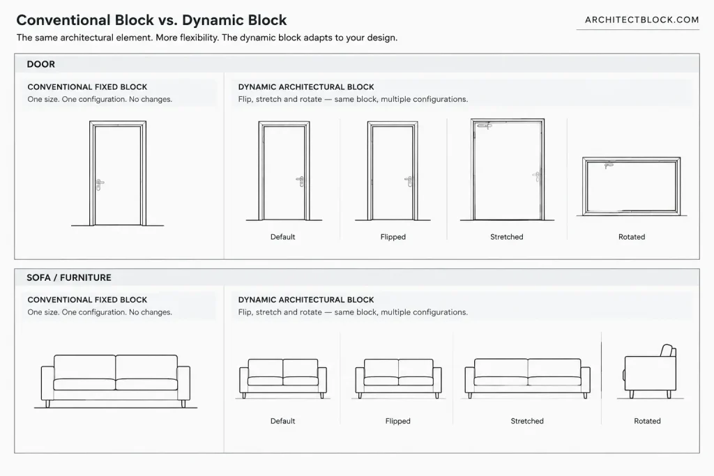
Dynamic blocks can reduce repetitive drafting by allowing one block definition to represent several related configurations. Instead of maintaining separate files for every door width, furniture orientation, or symbol variation, a carefully constructed block can expose controlled options such as stretching, flipping, rotating, or changing visibility.
That flexibility also creates risk. An overcomplicated block may be difficult to edit, slow to troubleshoot, or easy to place in an unintended configuration. The goal is not to make every architectural block dynamic. It is to use dynamic behavior where it improves consistency without hiding important design information.
What makes a block dynamic?
A conventional CAD block contains a fixed collection of objects referenced from a block definition. Users can insert, move, rotate, and scale the reference, but its internal arrangement remains unchanged unless the definition is edited.
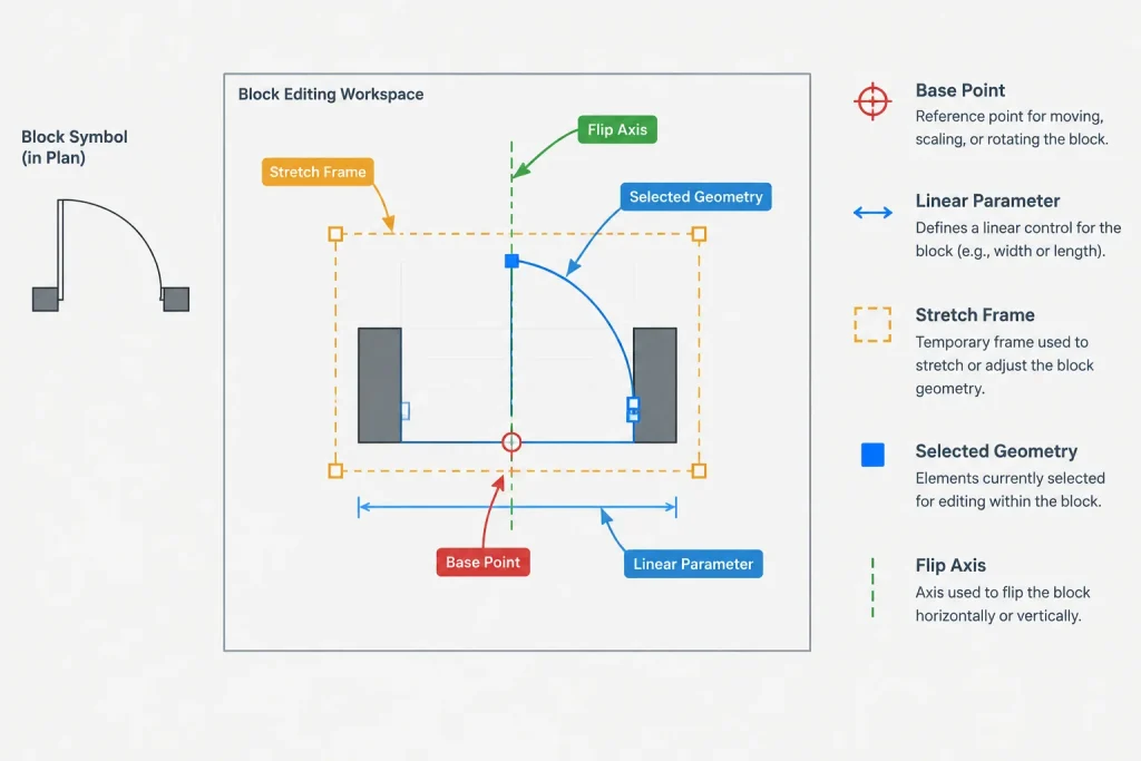
A dynamic block adds controlled behaviors within the block definition. In AutoCAD, these behaviors are commonly created in the Block Editor by combining parameters with actions. A parameter identifies a property or relationship that a user can manipulate. An action determines what happens to selected objects when that parameter changes.
Common behaviors include:
- Stretching: Moving selected vertices or objects to adjust a component’s length or width.
- Flipping: Reversing geometry across a defined axis without manually mirroring the entire block.
- Rotation: Rotating selected internal geometry around a controlled point.
- Visibility changes: Displaying one predefined group of objects while hiding others.
- Controlled selection: Offering a limited set of predefined configurations rather than permitting arbitrary changes.
These controls apply to the block reference. Multiple instances of the same definition can therefore display different permitted configurations while remaining related to one source definition.
Good architectural uses for dynamic blocks
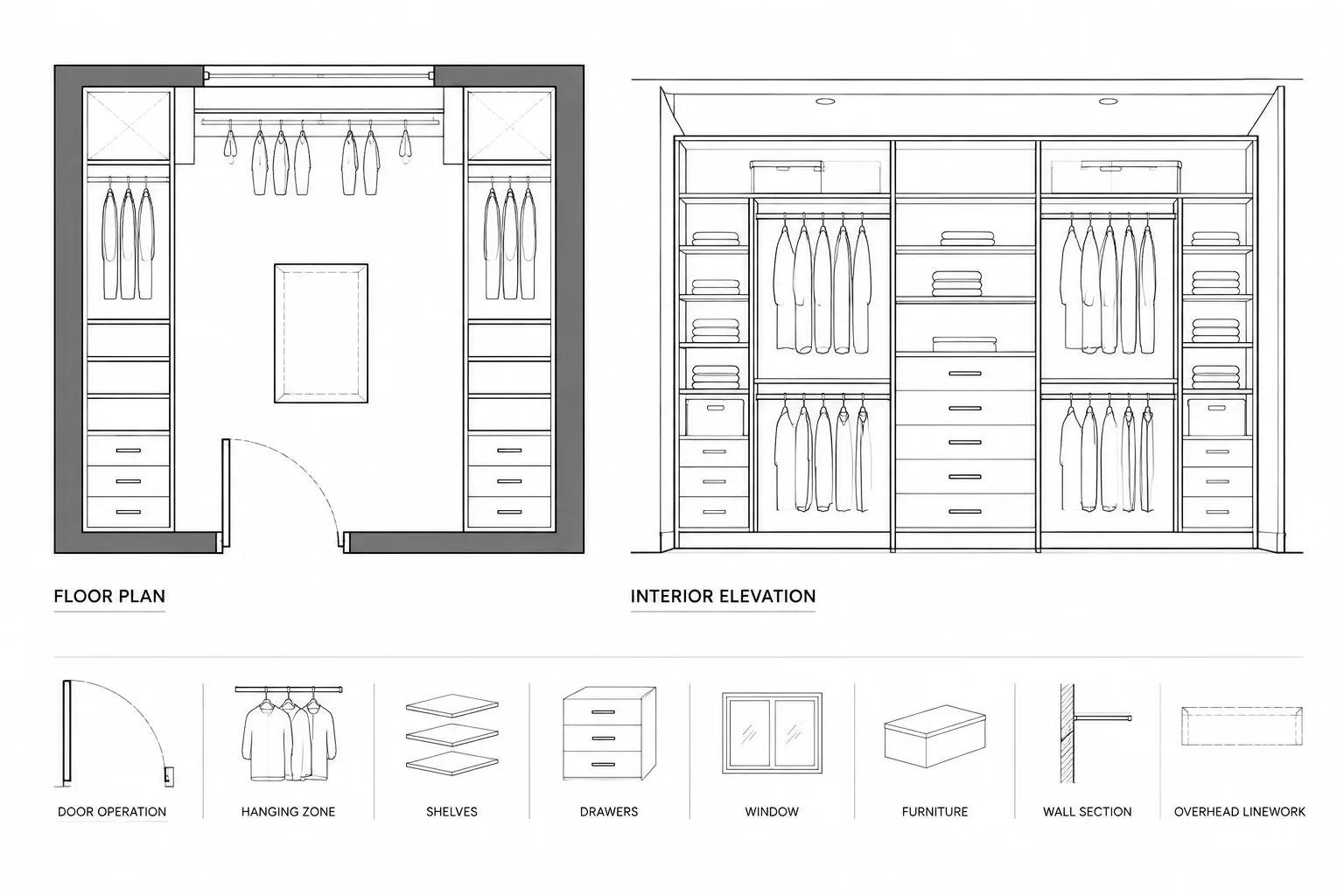
Dynamic behavior is most useful when components share a clear graphical structure but require predictable variations. Suitable candidates often include doors, windows, plumbing fixtures, furniture, casework modules, parking symbols, north arrows, section markers, and diagrammatic equipment.
Doors and openings
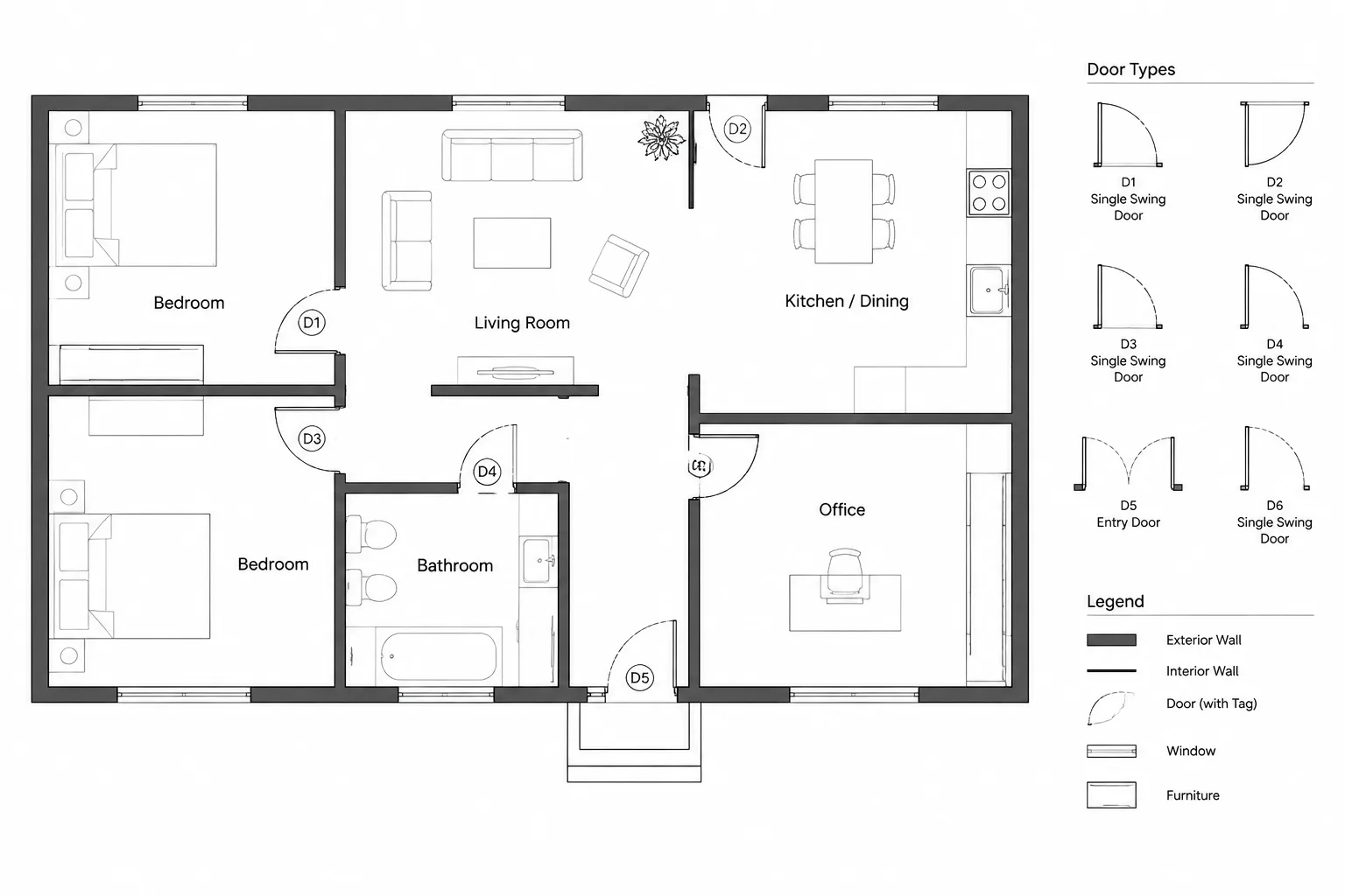
A door block may use a flip control to change handing and a stretch control to coordinate the leaf and opening graphics. The insertion point can remain at a jamb or another documented reference point. A visibility option might distinguish between related plan representations, but it should not combine unrelated door constructions merely because they look similar at a small drawing scale.
Door identifiers, hardware information, ratings, and schedule data require separate coordination. A geometric dynamic block does not establish that a particular configuration is compliant or appropriate for a project.
Furniture and fixtures
Furniture blocks can benefit from flip or rotation controls when orientation changes frequently. Stretching may be useful for generic planning objects whose dimensions are intentionally adjustable. It is less appropriate for a specific manufactured product with fixed proportions.
Keep clearance or access zones separate from the visible object where possible. They may be placed on a dedicated layer or controlled through a clearly named visibility state. Their presence should not be treated as proof that applicable project requirements have been satisfied.
Symbols and callouts
Drawing symbols can use visibility states to switch between graphic arrangements suited to different view conditions. For example, a marker may need a left-facing and right-facing composition so its text does not overlap nearby geometry. Dynamic controls can make that adjustment more reliable than exploding and manually rebuilding the symbol.
Choose the simplest control that solves the problem
Before opening the Block Editor, list the variations the block must support. Separate required behavior from optional convenience. A block that only needs to reverse orientation may require a flip parameter and action, not a network of stretches, rotations, and visibility states.
| Drafting need | Possible dynamic approach | Main coordination concern |
|---|---|---|
| Reverse a door or fixture | Flip parameter and flip action | Text, attributes, and asymmetrical details must remain readable and correct |
| Adjust a generic opening | Linear parameter and stretch action | All related lines, arcs, and annotation must update together |
| Select among known graphic options | Visibility states | Hidden geometry must not remain accidentally visible in plots |
| Reorient part of a symbol | Rotation parameter and rotate action | The base point and text orientation must be tested |
| Limit users to office-approved choices | Predefined values or a controlled selection method | Options must be named clearly and maintained when the library changes |
If the variations do not share meaningful geometry or data, separate block definitions may be clearer. Combining unrelated items into one large visibility-based block can make schedules, layer control, extraction, and future editing more difficult.
A practical block-building workflow
1. Define the block’s purpose
Write a short description of what the block represents and where it will be used. Identify whether it is a planning symbol, a construction-document component, a diagrammatic object, or a detail element. This helps prevent users from assigning more accuracy to the block than it contains.
2. Establish clean source geometry
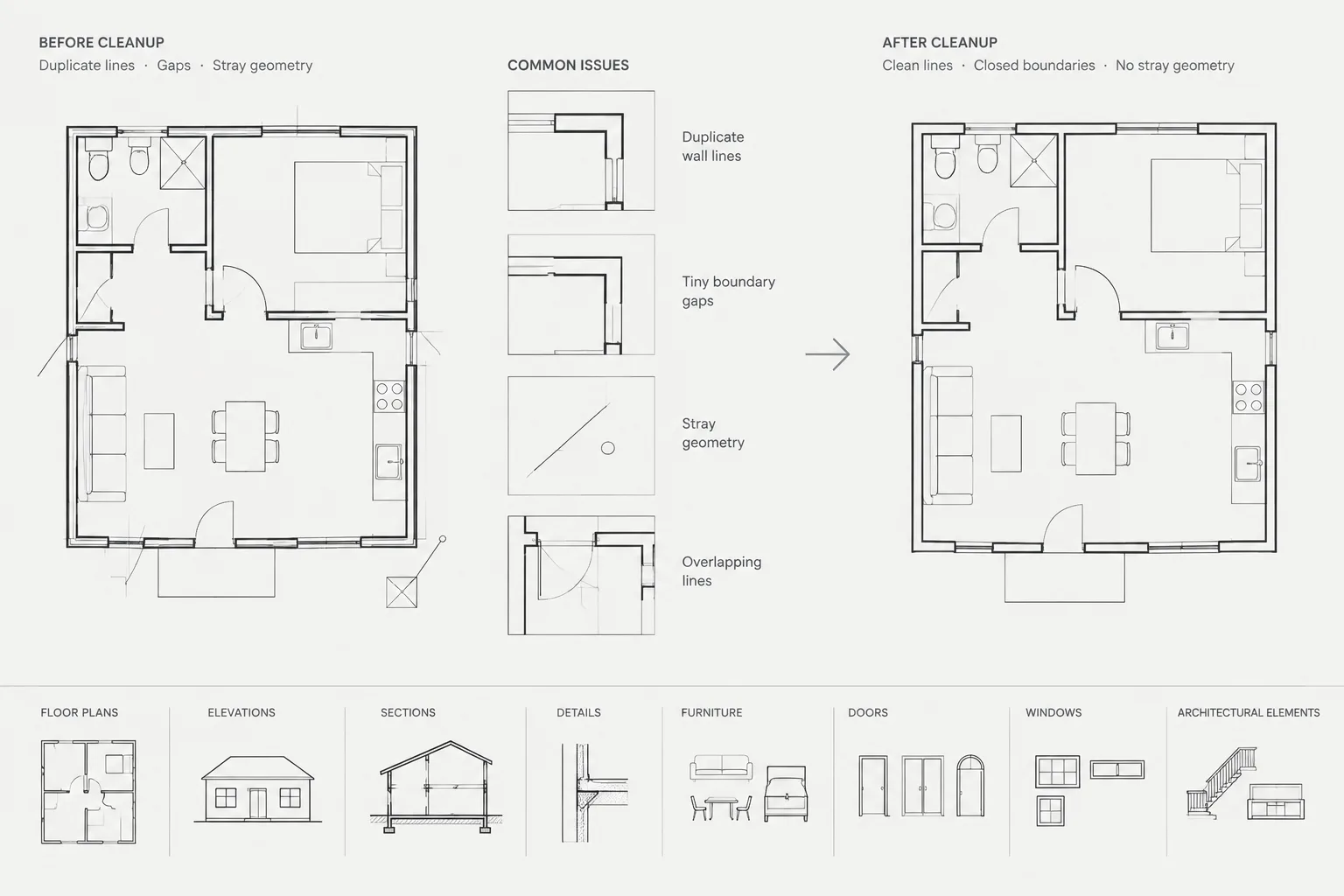
Remove duplicate lines, stray objects, unnecessary hatches, and unexplained overrides before creating dynamic behavior. Confirm that object properties follow the intended layer, color, linetype, and lineweight strategy. Dynamic actions applied to disorganized geometry are harder to diagnose later.
3. Select a dependable base point
The insertion point should correspond to a repeatable architectural reference, such as a jamb, centerline, corner, or fixture connection reference. Avoid choosing a visually convenient point that becomes ambiguous after the block is flipped or stretched.
4. Add one behavior at a time
Create the simplest parameter-action pair first and test it before adding another. When building a stretch behavior, pay close attention to the action’s selection set and stretch frame. Objects that should move rigidly and vertices that should stretch may require different treatment.
After each addition, test the block outside the editing environment. Incremental testing makes it easier to identify which new behavior caused an error.
5. Name controls for users
Use property labels and visibility-state names that describe an architectural result rather than an internal drafting trick. Names such as left orientation, right orientation, open graphic, or closed graphic are more useful than vague labels such as option one and option two.
6. Coordinate attributes and text
Attributes may need to remain horizontal, move with a component, or stay in a consistent location while geometry changes. Test each requirement deliberately. A flip or rotate action that works for linework can leave text mirrored, upside down, or detached from its marker.
Do not duplicate project information across unrelated attributes unless there is a clear maintenance process. A dynamic block should not become a substitute for coordinated schedules and drawing notes.
Test every permitted configuration
A successful test checks more than whether a grip moves. Insert fresh block references and evaluate all intended control combinations. Testing only the original instance can hide problems caused by previously edited references.
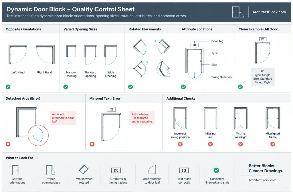
- Confirm that grips are understandable and positioned where users expect them.
- Exercise each flip, stretch, rotation, and visibility option.
- Test controls in combination, because one action may interfere with another.
- Check that arcs, hatches, wipeouts, and nested objects remain coordinated.
- Verify that attributes and text remain readable.
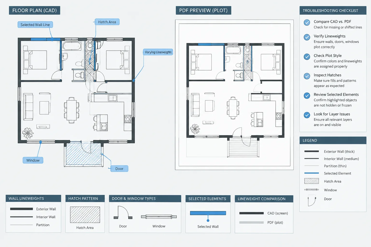
- Review layer behavior and plotted linework in representative viewports.
- Copy, rotate, and mirror references to identify orientation problems.
- Confirm that scheduled or extracted properties still communicate the intended information.
- Save, close, and reopen the DWG to verify that the block remains stable.
Also test what happens when a user attempts an unintended edit. If unrestricted stretching can produce meaningless geometry, constrain the available choices or use separate block definitions.
Avoid using block scale as a size selector
Uniform or nonuniform reference scaling can make a symbol appear to fit, but it can also distort linework, text, circles, hatch patterns, and extracted properties. For architectural components, size changes should normally be handled through intentionally designed block behavior or through distinct verified definitions.
Reference scale remains useful for some purely graphic symbols, but it should not silently redefine the physical size of a door, fixture, appliance, or construction component.
Maintain dynamic blocks as library assets
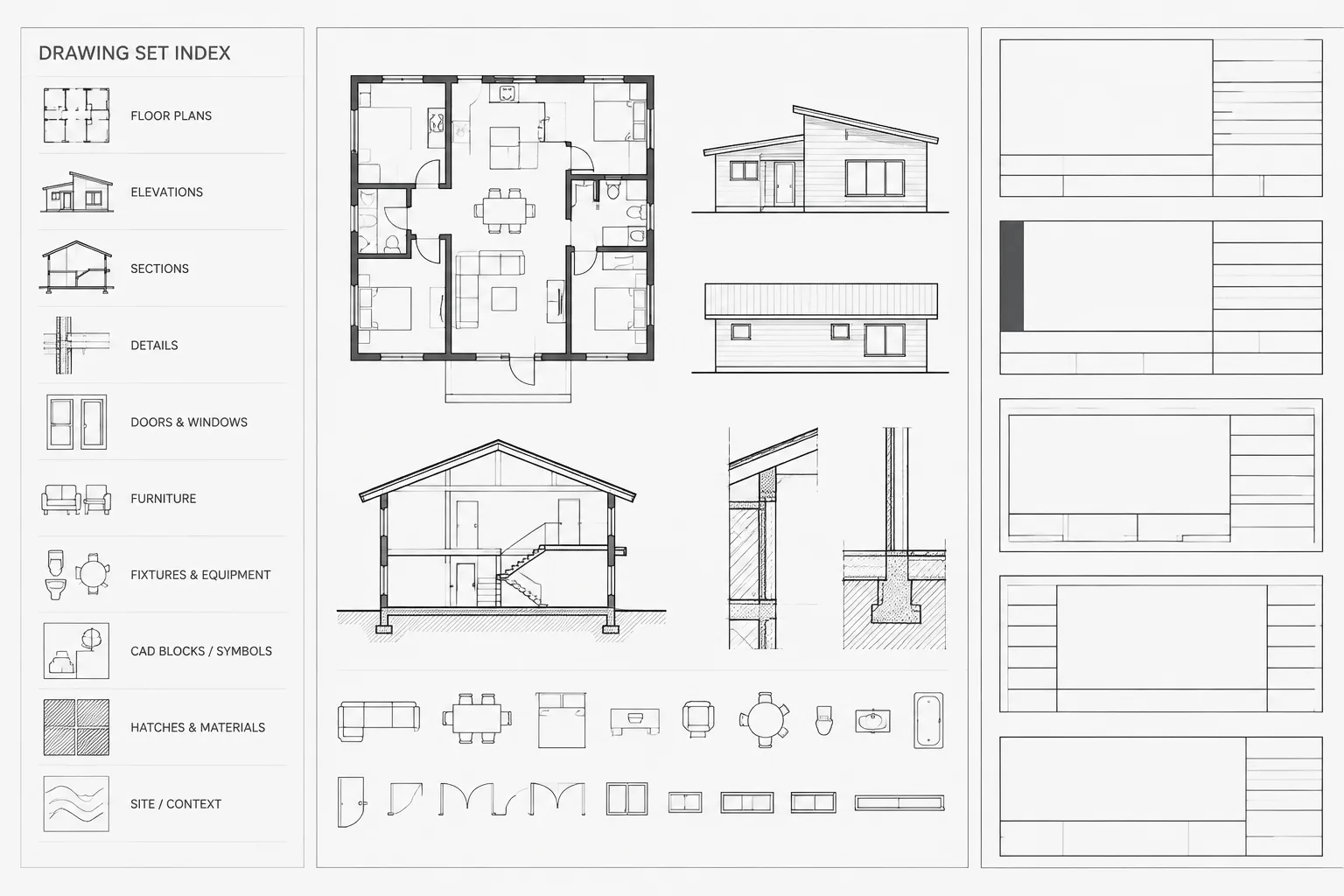
A dynamic block library needs ownership and documentation. Record the block’s purpose, insertion point, supported controls, layer expectations, and known limitations. When revising a definition, test it in a controlled file before replacing instances across active project drawings.
Be cautious when redefining a block that already exists in a project. Added or renamed visibility states, modified attributes, and changed parameter behavior may affect existing references differently from new insertions. Review representative instances after any update rather than assuming the revised definition is backward-compatible.
When a standard block is the better choice
Use a conventional block when the component has one stable representation, when variations are rare, or when separate identities are important for scheduling and coordination. A simple block is easier to inspect, exchange, and troubleshoot.
Dynamic blocks provide the greatest value when their choices are limited, predictable, and clearly named. A good dynamic block shortens repetitive work while preserving drawing clarity. If users need instructions just to discover what a block represents, the definition probably needs to be simplified or divided into separate library assets.
A practical release check for a dynamic block library
Before publishing a dynamic block for office use, review it from the perspective of someone who did not create it. The user should be able to identify the block, understand its available controls, and produce an intended configuration without opening the Block Editor.
- Identity: Confirm that every permitted state still represents the same architectural component or symbol family.
- Placement: Verify that the base point remains useful after flipping, rotating, or stretching the reference.
- Control clarity: Remove redundant grips and replace ambiguous labels with names that describe visible results.
- Graphic coordination: Check linework, hatches, wipeouts, nested content, attributes, and text in every supported state.
- Property consistency: Confirm that layers and object properties continue to follow the intended drawing standards.
- Data coordination: Make sure geometric changes do not imply schedule or specification information that the block does not actually maintain.
- Library documentation: Record what the block represents, how it should be inserted, which controls are supported, and what users must verify separately.
A focused troubleshooting sequence
When a dynamic block behaves incorrectly, begin with a fresh insertion rather than an extensively edited reference. Reproduce the problem using one control at a time, then test the same controls together. This helps distinguish a faulty action from an interaction between otherwise functional behaviors.
For a stretch problem, inspect both the action selection set and the stretch boundary. Determine which objects should move as complete objects and which vertices should change position. For orientation problems, review the parameter location, action base point, attribute behavior, and any asymmetrical geometry. For visibility problems, inspect every state for objects that were unintentionally included or omitted.
After correcting the definition, repeat the normal placement operations used in project drawings. A block that works only in its original orientation has not been fully tested. Save and reopen the drawing as part of the final review, and examine representative existing references before distributing a revised library definition.
Frequently asked questions
Should every architectural CAD block be dynamic?
No. Dynamic behavior is useful when related configurations share a clear identity and predictable geometry. A fixed block is usually easier to inspect and maintain when the representation rarely changes or when each variation must remain separately identifiable.
When should visibility states be used instead of separate blocks?
Visibility states work well for approved graphic alternatives that belong to the same underlying symbol or component. Separate blocks are clearer when the alternatives represent different products, constructions, schedule identities, or documentation purposes.
Why does a stretch grip move some objects but distort others?
A stretch action treats objects differently depending on how they intersect its selection boundary and how the action selection set was created. Review which vertices are intended to stretch and which objects should move without changing shape. Nested objects, hatches, and arcs also require deliberate testing.
How should attributes behave in a dynamic block?
Attribute behavior should follow the communication goal of the symbol. Some attributes may need to move with the geometry, while others should remain consistently positioned and readable. Test flipping, rotation, stretching, and visibility changes rather than assuming text will follow linework correctly.
Can a dynamic block guarantee that a component is code compliant?
No. A dynamic block controls drawing geometry and permitted graphic options. It does not independently verify project conditions, product requirements, accessibility, fire and life-safety criteria, structural performance, or other professional design obligations.
Why might existing references behave differently after a block is redefined?
Existing references may retain prior states, attribute values, orientations, or other reference-specific conditions. Changes to parameters, actions, visibility names, or attributes can therefore affect old and newly inserted references differently. Test representative existing instances before applying a revised definition broadly.
What is the clearest sign that a dynamic block has become too complex?
Complexity has become counterproductive when users cannot predict what the controls do, unrelated components are bundled into one definition, or routine corrections require repeated work in the Block Editor. Simplifying the behavior or dividing the content into separate blocks can improve reliability.