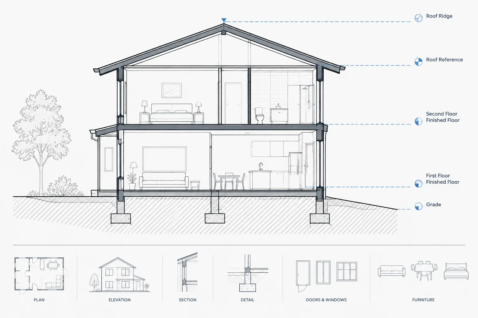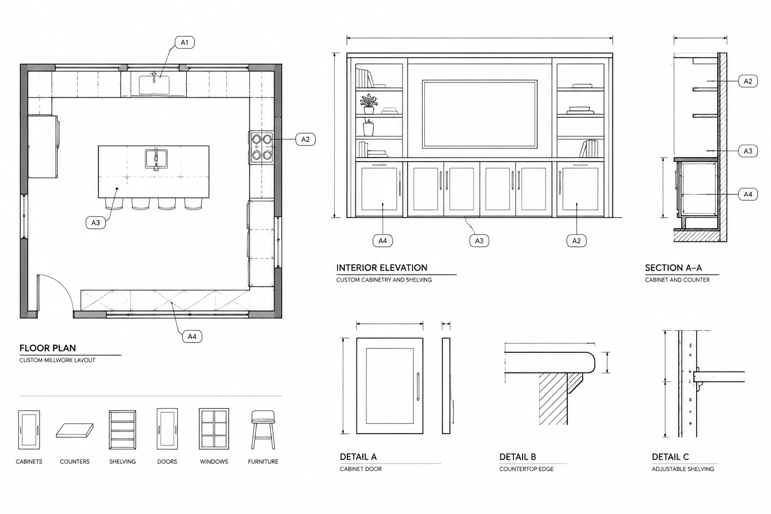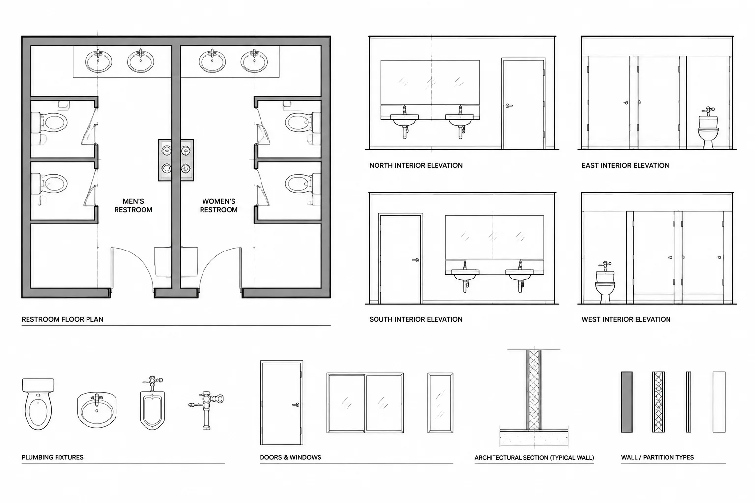
Plumbing fixtures appear in several parts of an architectural drawing set. A sink may be shown in a floor plan, enlarged restroom plan, interior elevation, section, finish plan, equipment schedule, and plumbing consultant drawing. If each view is drafted independently, fixture locations and types can quickly become inconsistent.
Effective plumbing fixture CAD coordination is not simply a matter of inserting toilet, sink, bathtub, or shower blocks. The architectural team must control what each symbol represents, where it is located, which drawing contains the governing information, and how changes are communicated to consultants. The following workflow helps keep fixture graphics useful without implying unverified dimensions, clearances, or product requirements.
Define the Architectural Scope First
Before placing fixtures, decide what the architectural drawings need to communicate. This varies by project and drawing phase. Early plans may use generic fixture outlines to test room layouts. Later drawings may need coordinated types, mounting relationships, accessories, casework interfaces, and references to schedules or specifications.
Architectural drawings commonly communicate:
- The fixture’s general location and orientation.
- Its relationship to walls, partitions, doors, counters, and adjacent equipment.
- A fixture type or tag when multiple configurations are used.
- Relevant mounting or alignment information shown in elevations and sections.
- Required coordination zones around the fixture.
- Interfaces with countertops, cabinets, tile, mirrors, and accessories.
Architectural drawings should not silently replace plumbing engineering documents. Supply, waste, vent, equipment connection, and engineering design information should be coordinated with the responsible consultant. The division of information should be established before the drawing set becomes crowded with duplicated notes.
Start with a Controlled Fixture Block Library
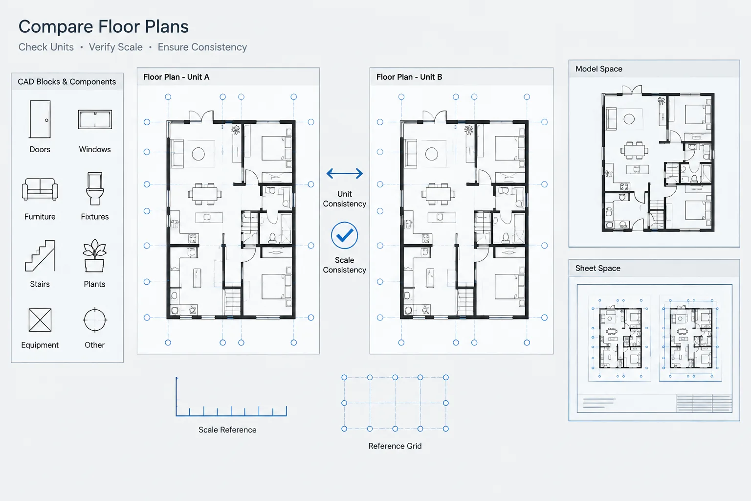
Downloaded plumbing fixture CAD blocks are useful starting points, but they should be reviewed before being placed in a project. A block may be drawn in unfamiliar units, contain excessive detail, use unrelated layers, or depict a specific product that has not been selected.
Review each source block
Open or inspect the block in a controlled file and check:
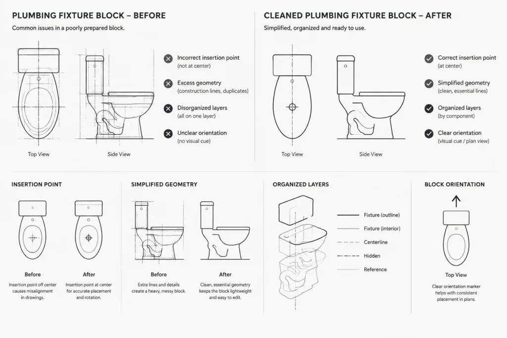
- Drawing units and apparent scale.
- Overall geometry against verified project or manufacturer information.
- Layer names, colors, linetypes, and lineweights.
- Duplicate, hidden, or unnecessary objects.
- Insertion point and orientation.
- Whether the block is generic or product-specific.
- Whether plan, elevation, and side-view graphics represent the same fixture.
Do not scale a fixture block merely to make it fit a room. If the actual fixture cannot fit the proposed location, the room layout or fixture selection needs review. Arbitrary scaling can conceal a coordination problem and produce misleading elevations.
Use predictable insertion points
A useful insertion point should support repeatable placement. Depending on the fixture, this may be a centerline, wall-contact point, drain reference, or another clearly documented control point. The best choice is the one that allows the project team to position and replace the block consistently.
Avoid insertion points located far from the visible geometry. Remote base points make blocks difficult to move, rotate, and compare. If a fixture has several valid control references, add nonplotting construction geometry within the source block or document the intended placement method in the library.
Place Fixtures from Architectural Control Geometry
Fixtures should be positioned from stable architectural references rather than nearby annotation or temporary lines. Suitable references may include finished wall faces, partition centerlines, countertop edges, structural grids, or room control lines. Choose the reference that corresponds to the project team’s dimensioning method.
Use temporary construction lines to test alignment before adding dimensions. For repeated rooms, compare equivalent fixtures rather than assuming copied rooms remain identical. Wall types, chase depths, door positions, and finish build-ups may vary even when the rooms look similar.
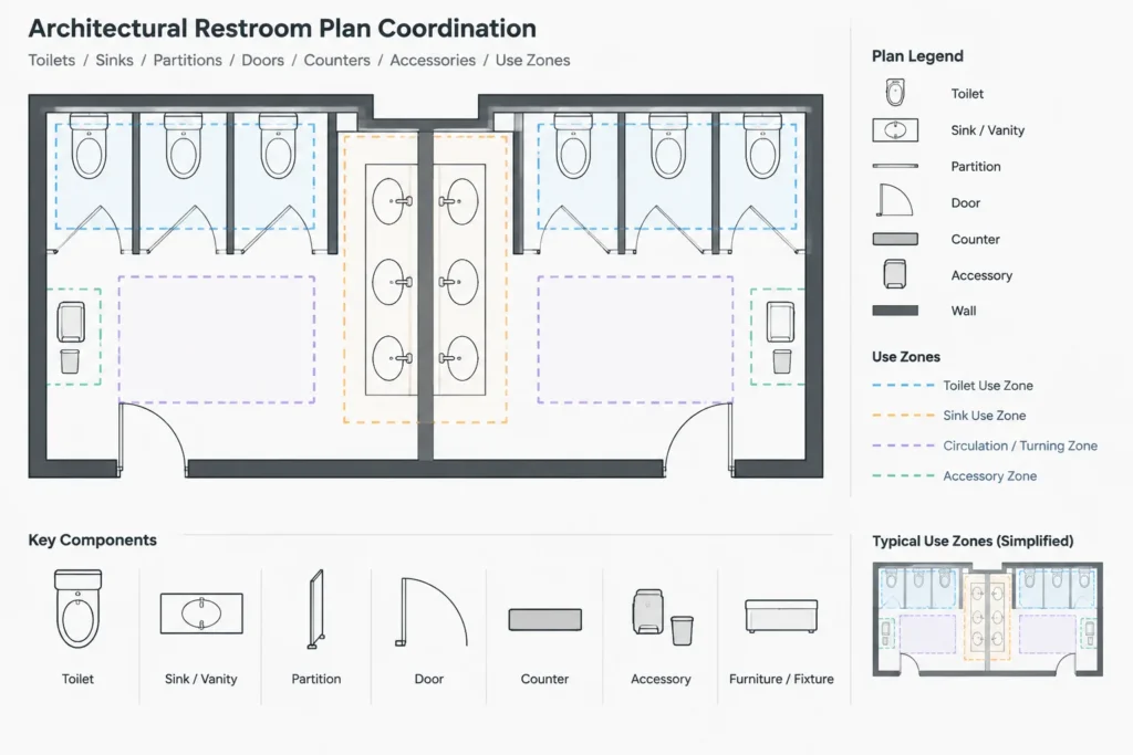
Check the complete use zone
The visible outline of a fixture is only part of its spatial impact. Coordination may also involve door swings, cabinet doors, approach space, user movement, grab bars, dispensers, shower controls, curtains or screens, and maintenance access.
Where regulated clearances apply, verify them against the governing requirements for the project’s location and occupancy. Do not rely on a generic CAD block to confirm accessibility or code compliance. A block can illustrate a clearance zone, but its geometry and application must be checked for the specific project.
Coordinate Plans with Elevations and Sections
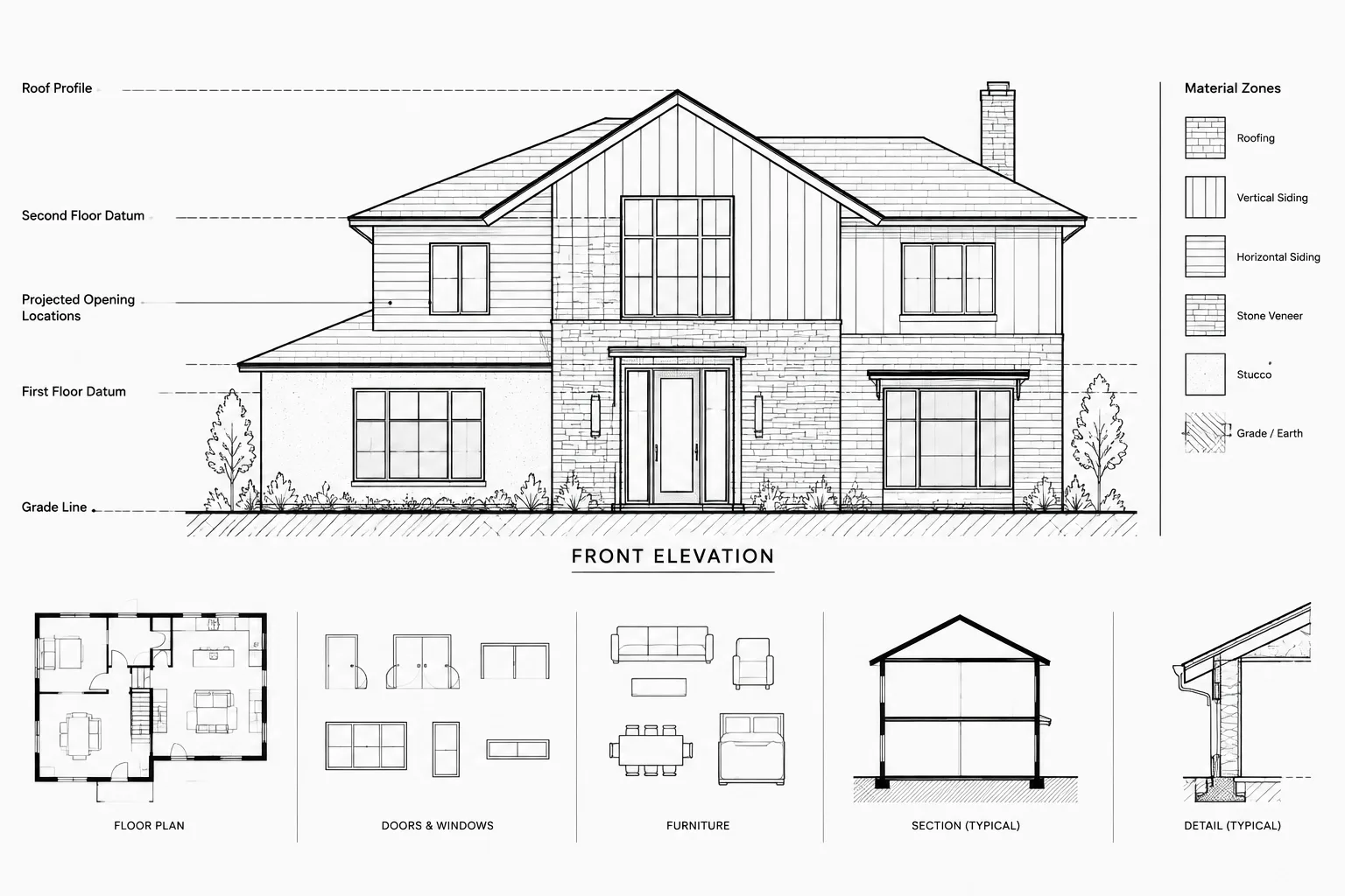
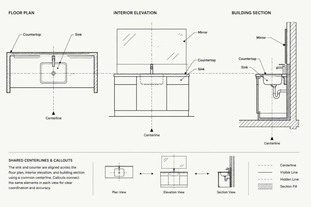
A plan establishes horizontal placement, while an elevation or section explains vertical relationships. Both should describe the same design decision.
After the plan layout is stable, project control lines into the related interior elevations. Confirm that:
- Fixture centerlines align between views.
- Countertop-mounted and wall-mounted fixtures match the selected configuration.
- Mirrors, backsplashes, shelves, accessories, and wall finishes respond to the fixture location.
- Casework openings and countertop cutouts are coordinated.
- Sections are added where a plan and elevation cannot explain the assembly.
Do not treat elevation symbols as decorative representations. A plan block and elevation block taken from different libraries may depict incompatible shapes or installation types. When the exact product is known, update all relevant views from the same verified source information. When it is not known, keep the graphics generic and avoid false precision.
Separate Graphic Purpose with Layers
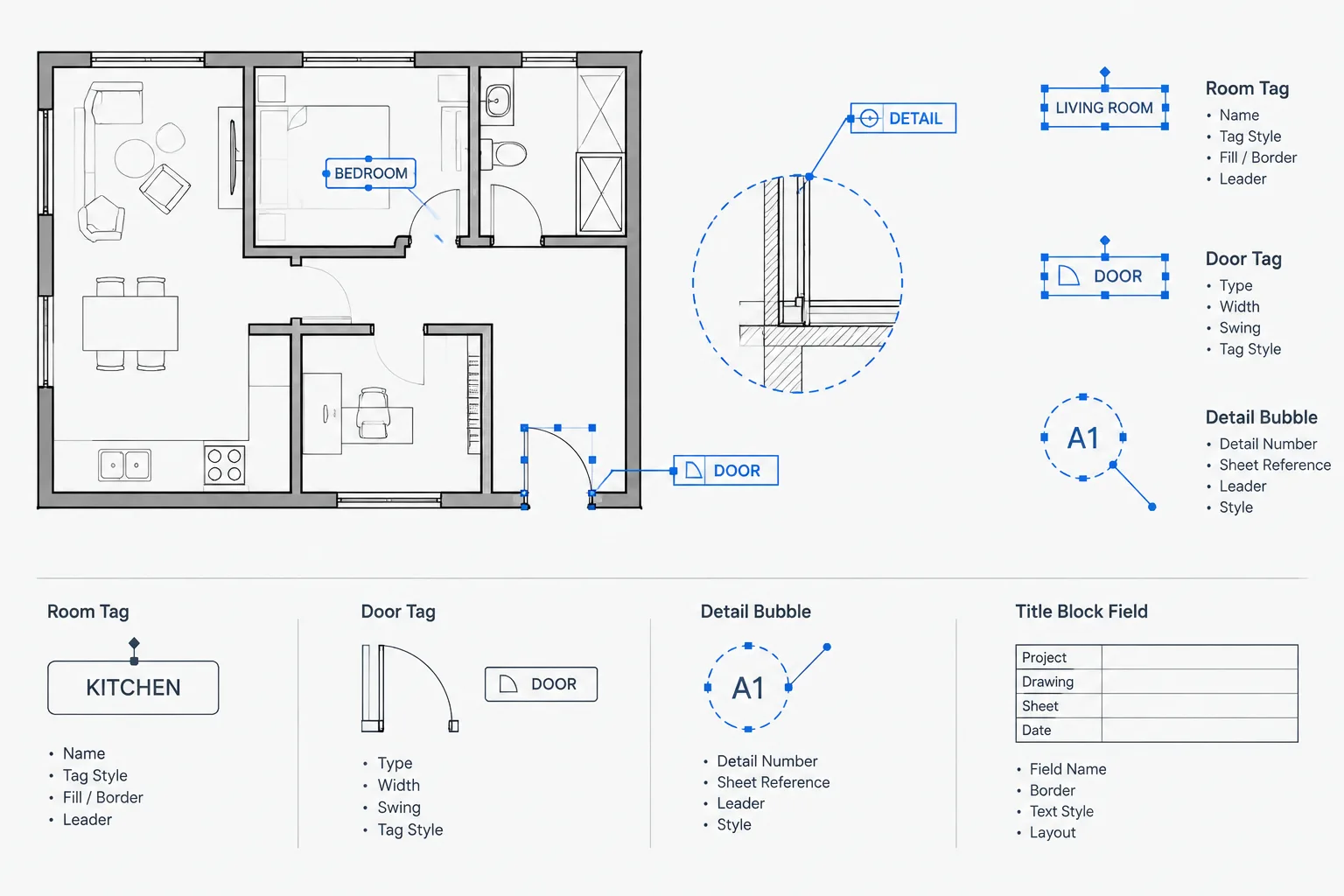
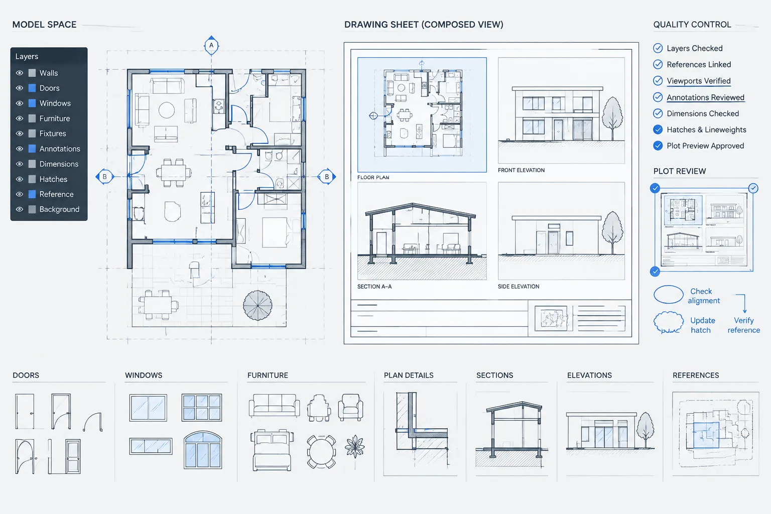
Fixture geometry, tags, clearances, and overhead elements serve different purposes and should not be merged into a single undifferentiated block. A practical layer strategy makes it possible to display the appropriate information in each viewport without editing the source geometry repeatedly.
| Drawing content | Coordination purpose | Typical plotting approach |
|---|---|---|
| Fixture outline | Shows location, size, and orientation | Visible architectural object line |
| Fixture tag | Connects the object to a schedule or legend | Readable annotation |
| Clearance or use zone | Supports layout review | Distinct linework; plotted only when needed |
| Hidden or overhead component | Explains elements outside the plan cut | Appropriate dashed or overhead convention |
| Consultant connection reference | Supports interdisciplinary review | Controlled according to project responsibility |
Layer names should follow the project’s established CAD standard. The important principle is functional separation, not a particular naming formula.
Use Fixture Tags Without Duplicating Information
A fixture tag should identify an item clearly and lead the reader to its governing information. It should not force the team to maintain the same product description in multiple places.
For example, the plan may carry a concise type identifier while a fixture schedule contains the coordinated description. Notes in elevations can then address installation relationships that are specific to that view. If the product changes, the team updates the schedule and affected geometry rather than searching every plan for repeated product text.
Where block attributes are used, establish which fields are controlled through the block and which remain in the schedule. Attributes can help with identification, but they do not automatically guarantee coordination. A clear review process is still necessary.
Compare Architectural and Consultant Backgrounds
Plumbing consultants often receive architectural backgrounds while the design is still changing. Subsequent wall, counter, or fixture moves can leave the consultant’s layout out of date. Coordination should therefore occur at planned milestones and after significant revisions.
A practical comparison sequence is:
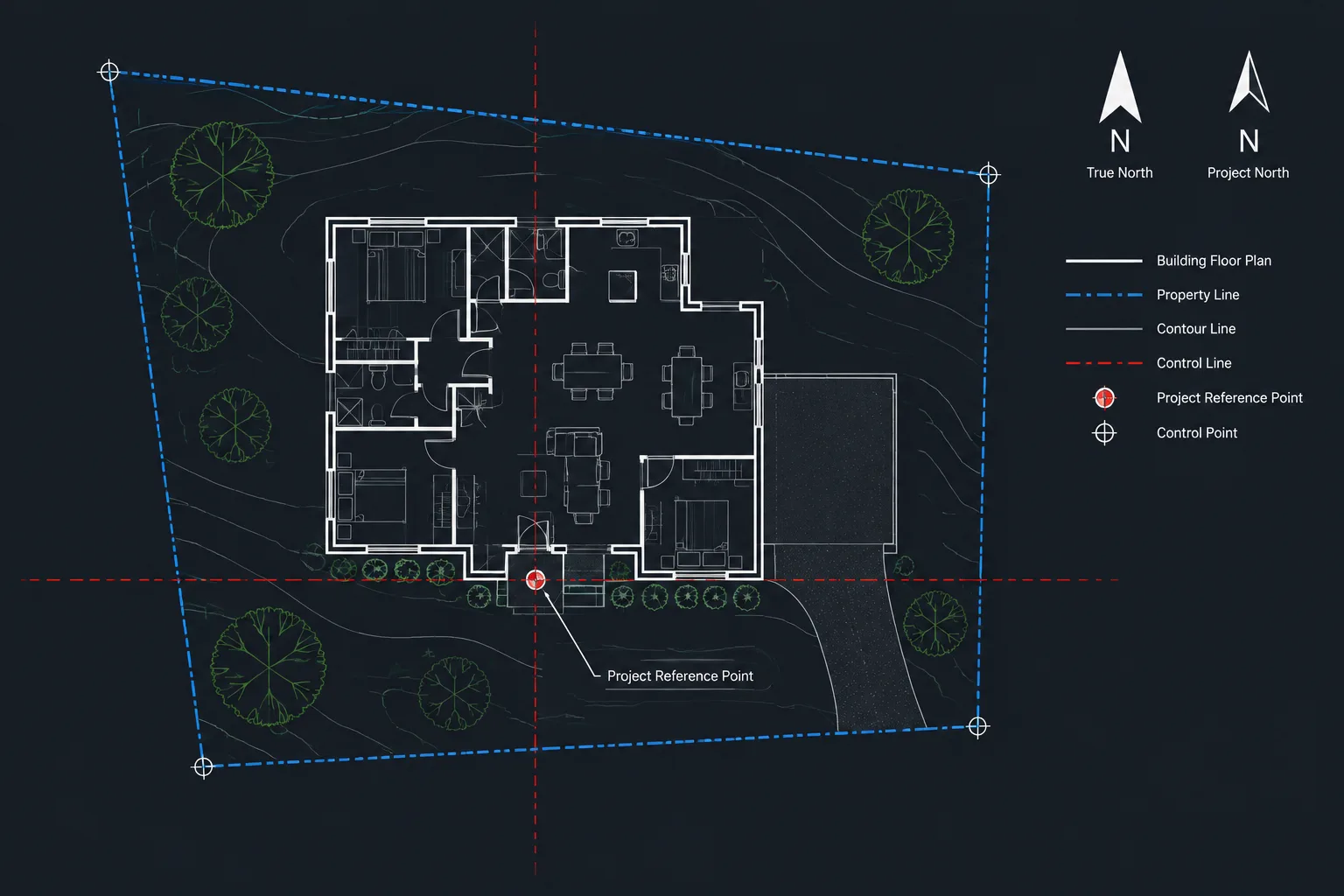
- Attach the current consultant drawing as an external reference using the agreed project coordinates.
- Control its display so architectural fixture outlines remain legible.
- Compare fixture locations, types, room arrangements, and chase conditions.
- Mark discrepancies on a dedicated coordination layer or issue log.
- Assign responsibility for each change rather than editing another discipline’s file without agreement.
- Reload the corrected reference and close resolved items.
Common discrepancies include mirrored layouts, deleted fixtures that remain in consultant drawings, moved partitions, changed countertop configurations, and duplicated fixtures from both the background and consultant model space.
Apply a Final Fixture Coordination Check
Before issuing a drawing set, review fixtures across the entire package rather than sheet by sheet. A focused check should ask:
- Does every tagged fixture have a corresponding schedule or legend entry?
- Are identical tags used for genuinely equivalent fixtures?
- Do plan, elevation, and section graphics agree?
- Are room names and enlarged-plan references current?
- Have accessibility and other regulated layouts been independently verified?
- Are fixture locations coordinated with doors, casework, finishes, and accessories?
- Does the latest consultant background reflect architectural changes?
- Are abandoned blocks, duplicate symbols, and obsolete notes removed?
- Do fixture graphics plot clearly at the intended sheet scale?
It is also helpful to inspect repeated room types together. Side-by-side review makes small inconsistencies easier to find than checking rooms in isolation.
Keep the Drawings Accurate Without Overdrawing
Plumbing fixture CAD coordination works best when the drawings show enough information to explain the design but avoid unsupported detail. Use controlled blocks, stable architectural references, coordinated tags, and purposeful layers. Verify product geometry and regulated clearances rather than trusting generic symbols.
The result should be a drawing set in which a fixture can be traced logically from plan to elevation, section, schedule, and consultant background. That continuity is more valuable than visual complexity and makes future revisions substantially easier to manage.