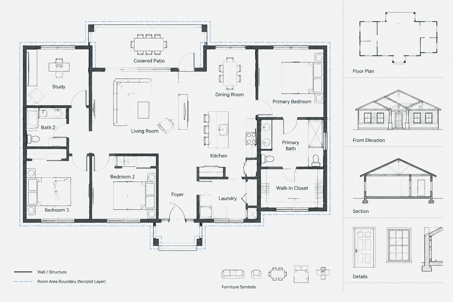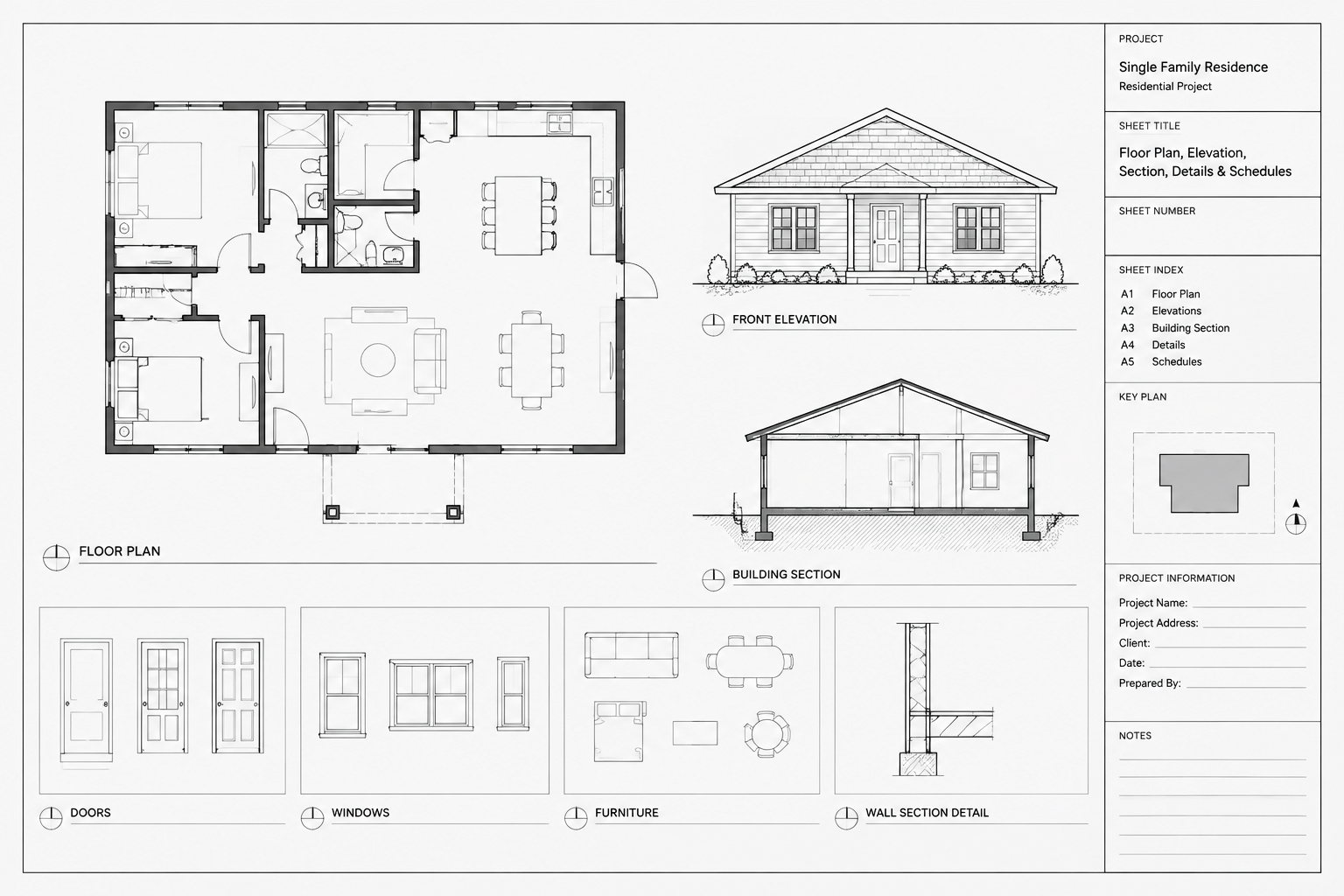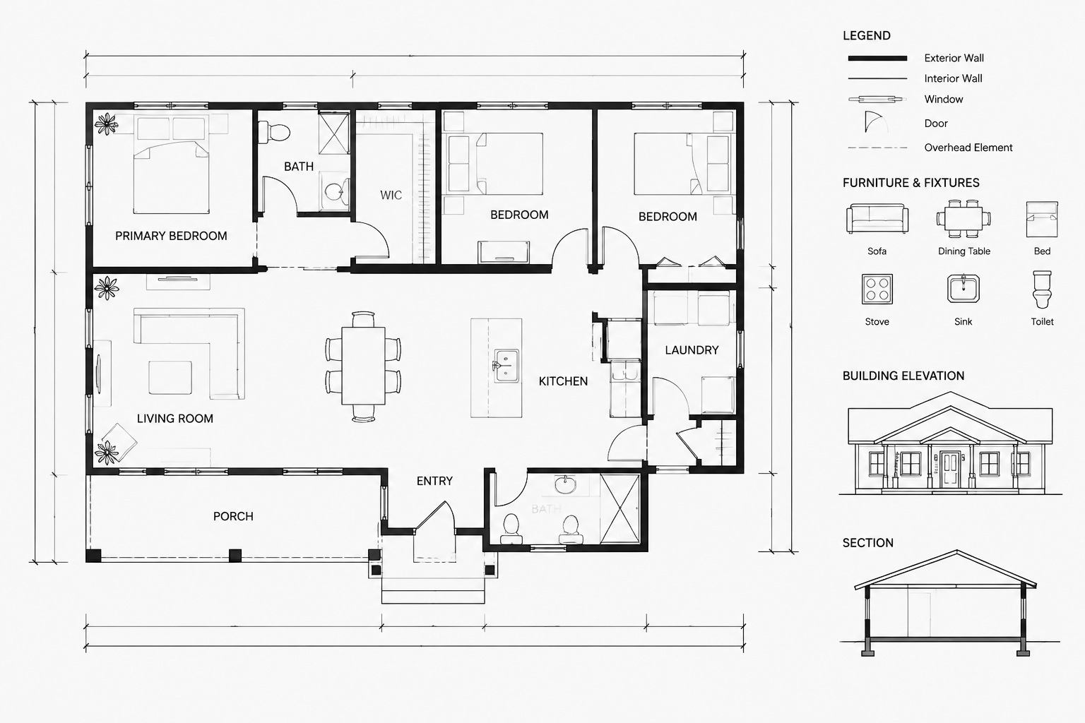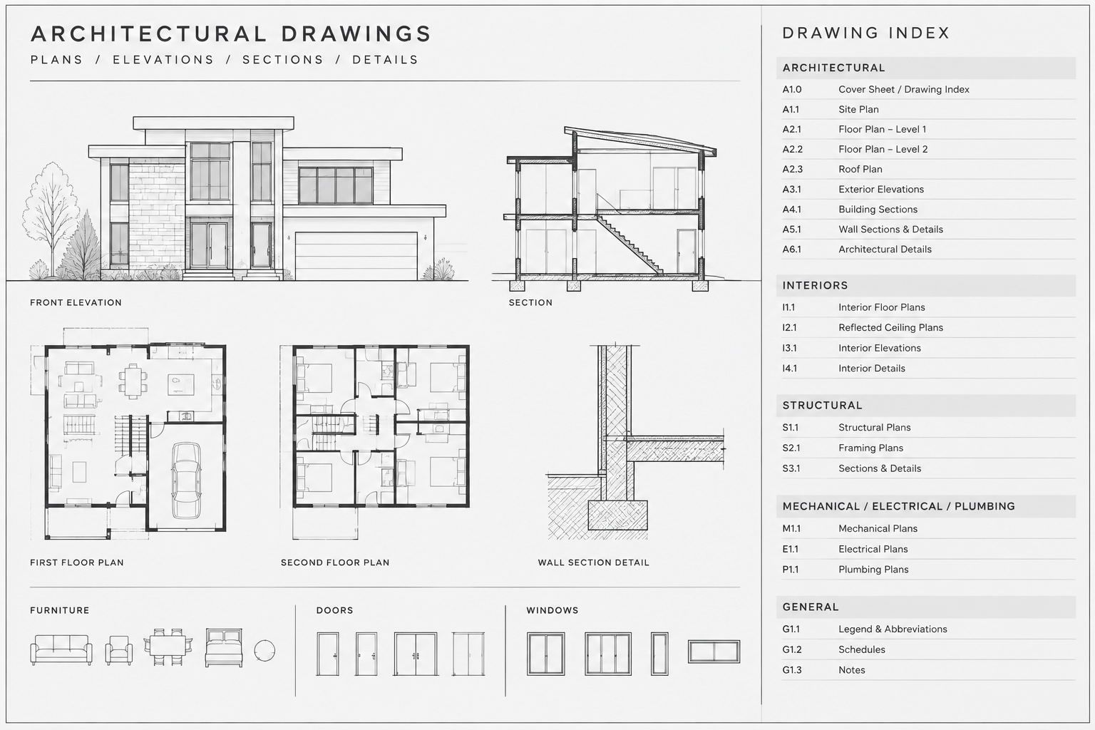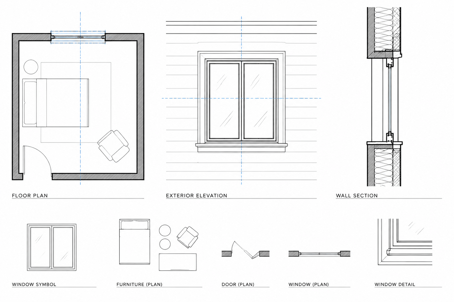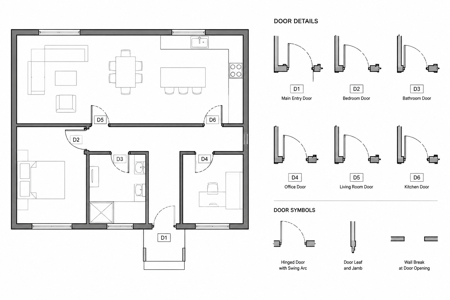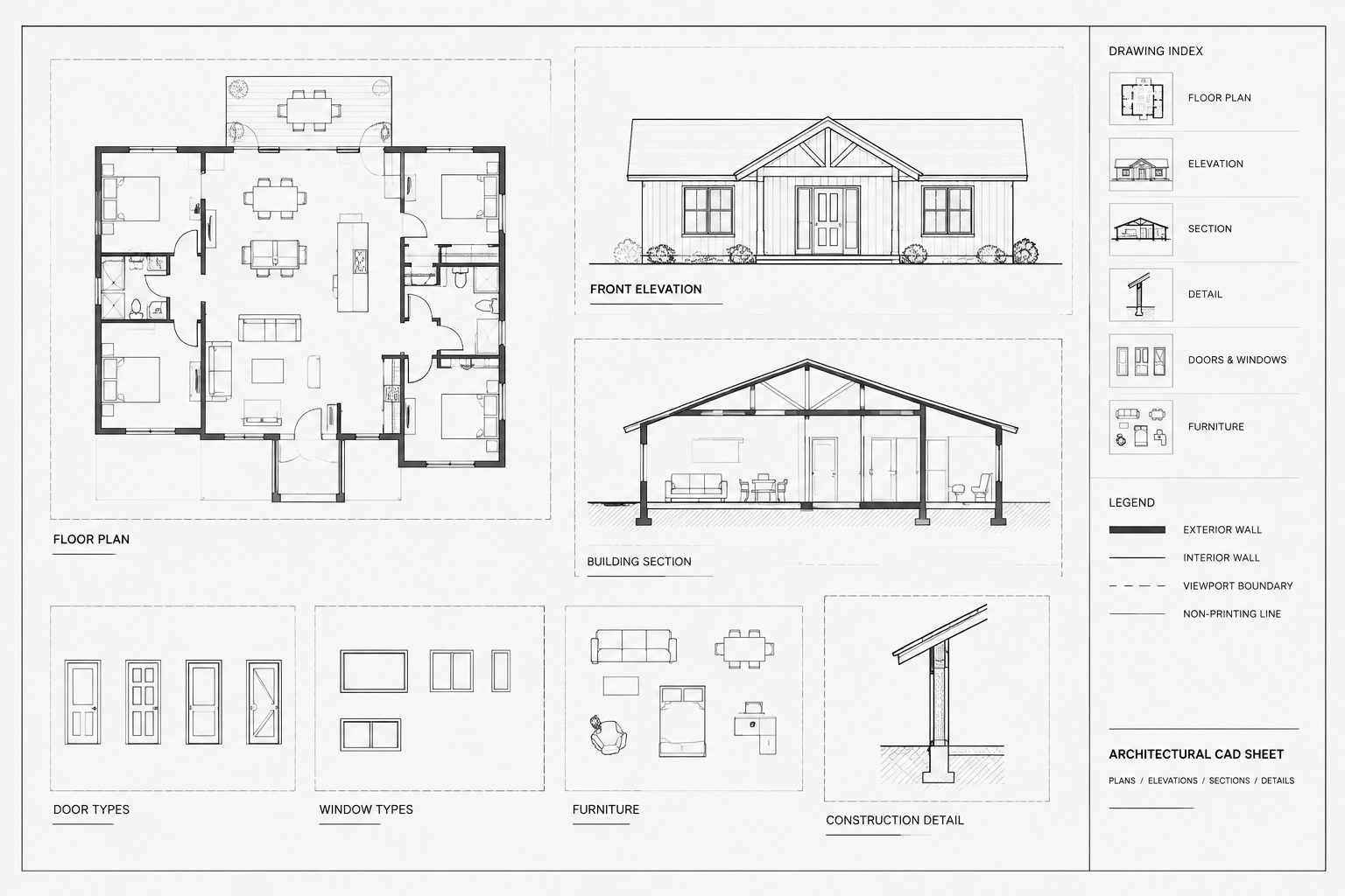
Architectural CAD viewports connect full-size model geometry to composed drawing sheets. A well-managed viewport shows the correct part of the building at the intended plotted scale, with an appropriate layer display and enough space for dimensions, notes, titles, and references. A poorly managed viewport can shift unexpectedly, display unwanted information, or plot at the wrong scale.
The most reliable approach is to treat each viewport as a controlled presentation window rather than an informal crop of model space. Its boundary, scale, view position, layer visibility, and annotation relationship should all support a specific drawing purpose.
Understand the role of a paper space viewport
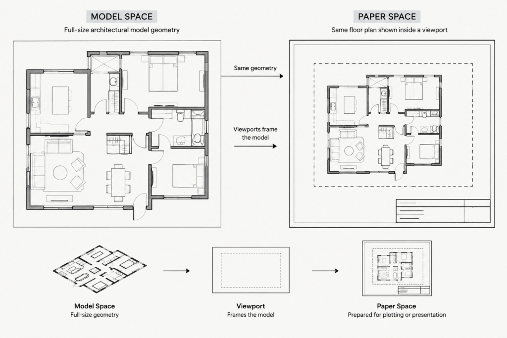
Building geometry is generally drafted at full size in model space. Sheets are composed in paper space, where the title block, sheet-based notes, and viewport boundaries are arranged relative to the plotted page.
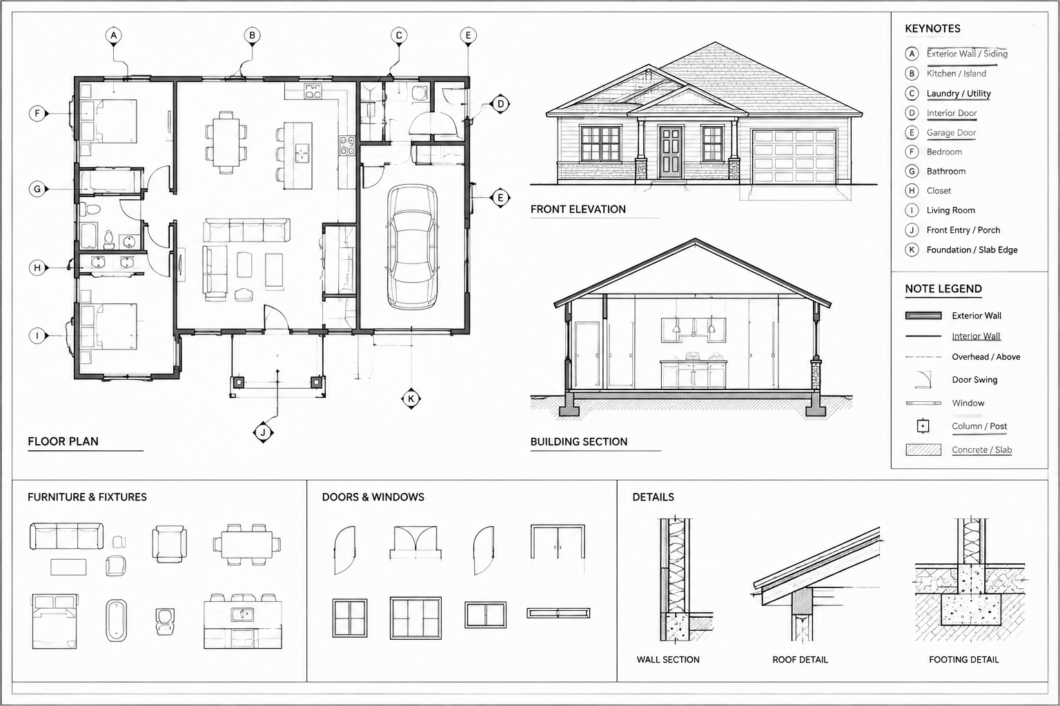
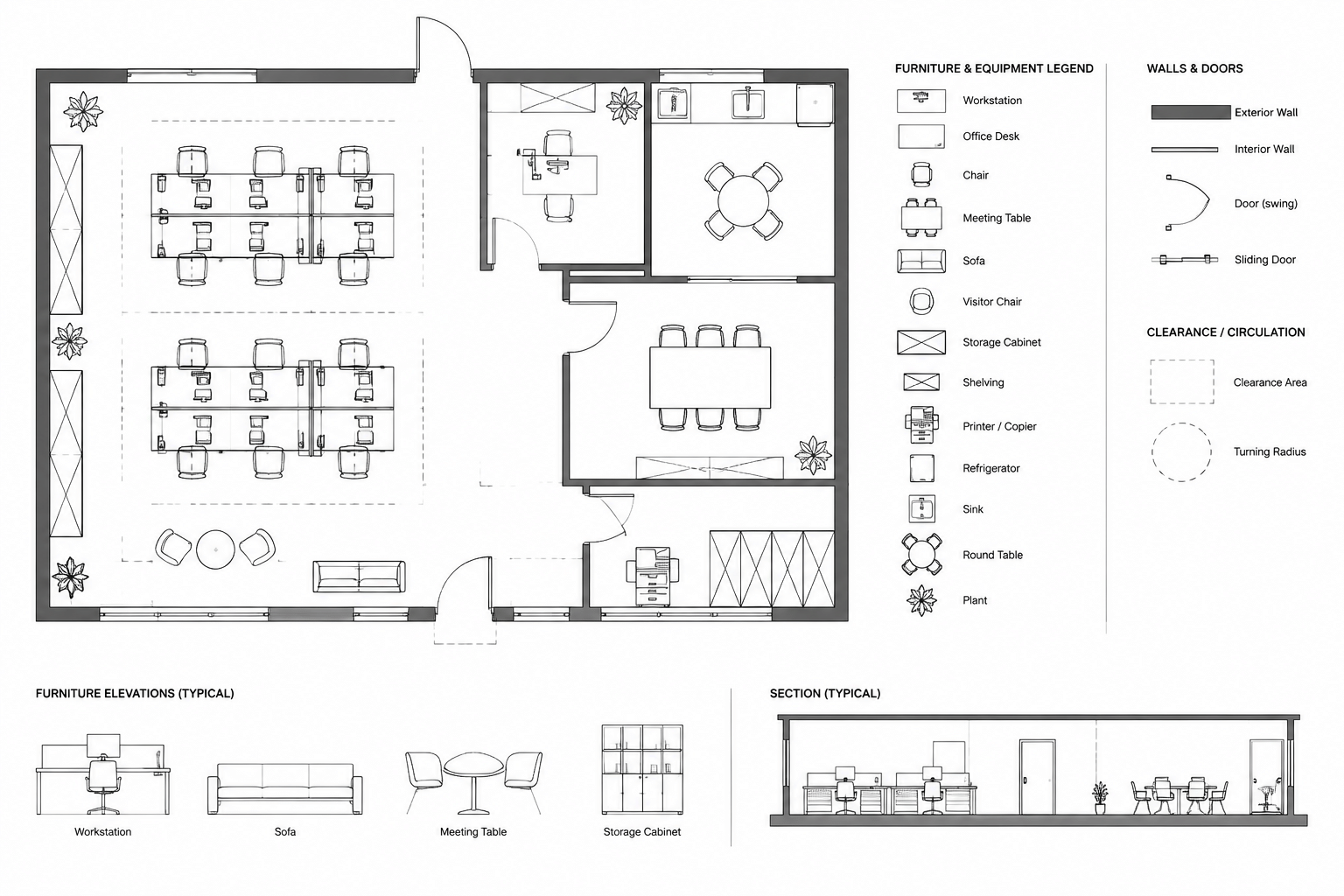
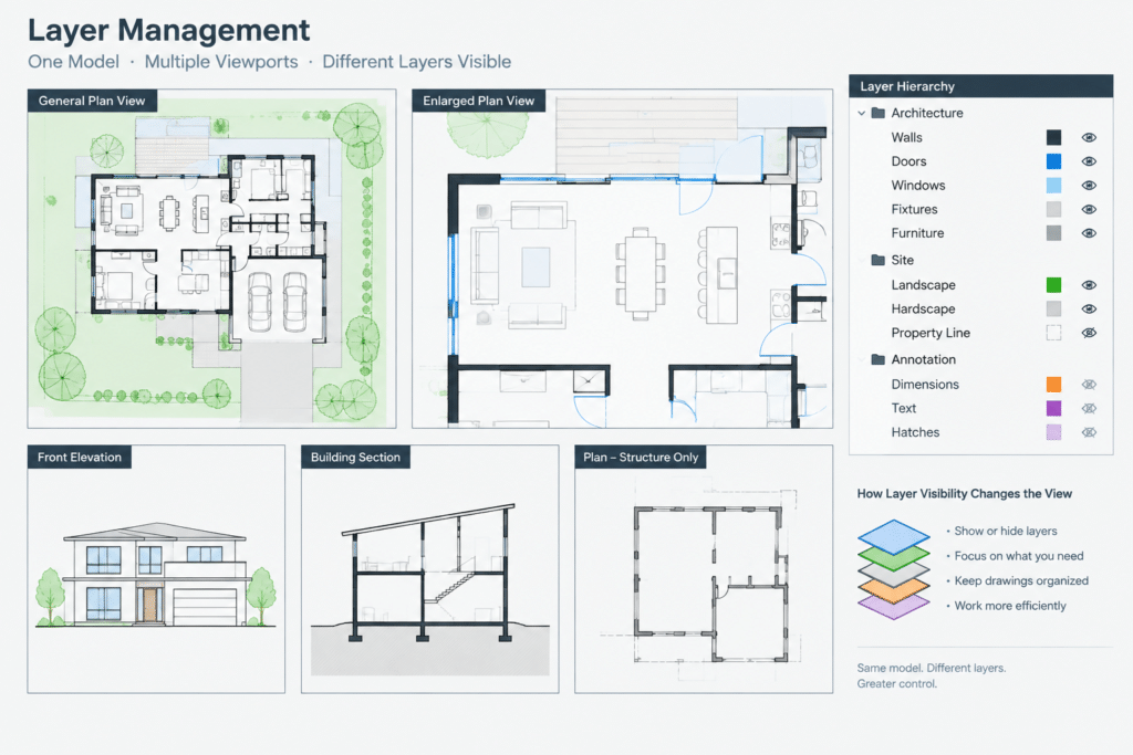
A paper space viewport displays selected model-space content without duplicating that content. Multiple viewports can show the same model at different scales or from different locations. For example, one sheet might contain a general floor plan and a separate enlarged plan, each looking into the same coordinated model geometry.
This separation is useful because a revision to the model can appear wherever that geometry is referenced. It also means that viewport management is part of drawing coordination, not merely page formatting.
Prepare the model before composing the sheet
Viewport setup is easier when the model is already organized. Before creating sheet views, check the following:
- Architectural elements are drawn at full size.
- Objects are assigned to meaningful layers rather than relying on a single general layer.
- Plans, elevations, sections, details, and reference geometry are positioned deliberately.
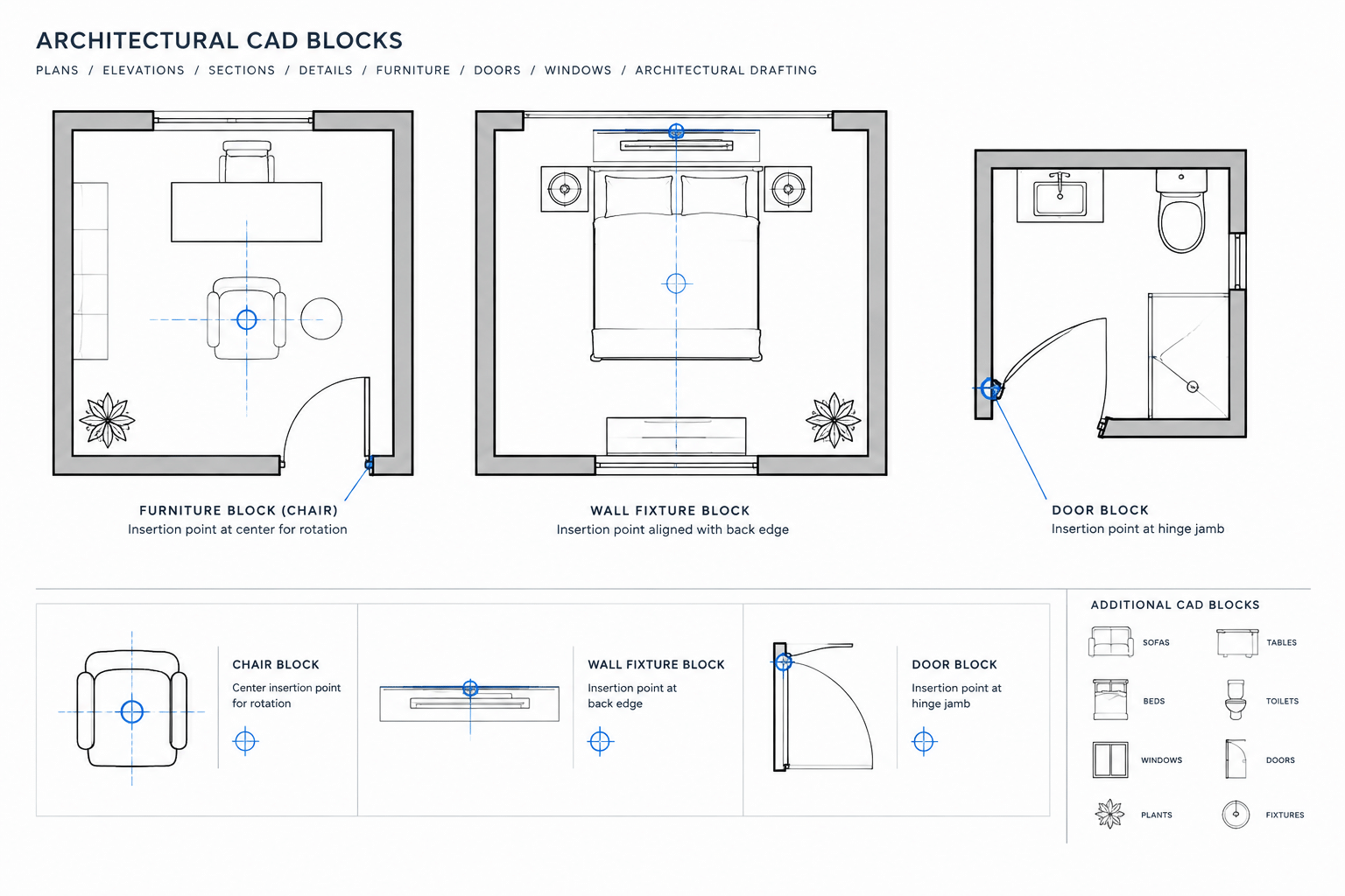
- External references use stable insertion points and consistent drawing units.
- Stray objects are removed or moved to an appropriate nonplotting or reference layer.
- The model has a clear orientation that the sheet views can follow.
A viewport should not become a substitute for cleaning the source drawing. Excessive panning, irregular clipping, and numerous layer overrides often indicate that the underlying model or file organization needs attention.
Create a viewport for a defined drawing purpose
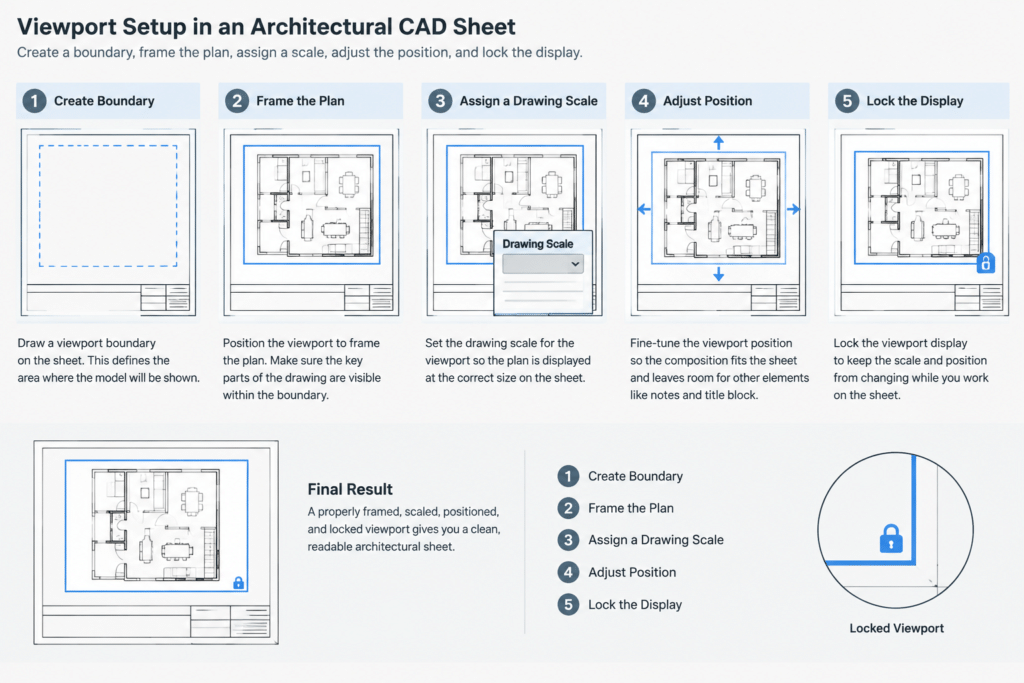
Start in the correct paper space layout and create the viewport within the usable drawing area. Its initial shape can be adjusted later, so focus first on the purpose of the view. Decide whether it is a general plan, enlarged plan, elevation, section, diagram, or detail.
Give the drawing title, related notes, and reference markers enough room. A viewport that fills every available gap may leave no clean location for annotation or future revisions. Sheet composition should be planned as a complete hierarchy rather than as a collection of maximum-size windows.
Keep viewport boundaries on a dedicated layer
Place viewport boundary objects on a clearly named layer reserved for viewports. Configure that layer so the boundary does not plot if the office drawing standard calls for an invisible frame. Do not simply erase a viewport edge after setup, because the boundary is the object that controls the view.
A dedicated layer also makes viewport boundaries easier to select, review, and protect. When several views overlap or align closely, consistent layer control reduces accidental edits.
Set the view before setting the final scale
Activate the viewport and navigate to the intended portion of the model. Establish the basic orientation and center the subject, but avoid spending too much time on exact positioning before selecting the scale. Changing the scale alters how much of the model fits within the viewport.
For a typical architectural plan, align the building consistently with the sheet unless there is a documented reason to rotate the view. Similar plans should generally use the same orientation so readers can compare levels and disciplines without mentally rotating the building from sheet to sheet.
If a view must be rotated for sheet fit or clarity, rotate the viewport view rather than rotating the building geometry solely for presentation. Record and review that decision carefully because north arrows, match lines, key plans, and related references must remain coordinated.
Assign and verify the viewport scale
Select the viewport and assign the required scale through its properties or the viewport scale control. Use the project’s approved drawing scales rather than choosing a scale only because it fills the sheet attractively.
After setting the scale, adjust the viewport boundary and pan the model into position. Do not use an unrestricted zoom operation to make final framing adjustments, because that can replace the intended scale with an arbitrary value. If the scale changes accidentally, restore it before continuing.
Scale selection should respond to the amount of information the drawing must communicate. A general plan needs enough room for overall organization and primary annotation. An enlarged plan can show denser dimensions, fixture relationships, and local construction information. The scale and content should therefore be selected together.
Check scale from viewport properties
Do not rely only on the apparent size of familiar objects. A door, fixture, or room can look plausible at several scales. Select the viewport and confirm its scale value directly. The drawing title beneath the viewport should report the same scale, unless the view is intentionally identified as not to scale.
Lock the viewport display
Once the view is positioned and scaled, lock the viewport display. Locking helps prevent accidental zooming or panning while editing model-space objects through the viewport.
A locked viewport does not prevent all changes to the drawing. The viewport boundary can still be moved or reshaped from paper space, and model objects can still be edited. The lock protects the displayed view position and magnification, which are the settings most easily disturbed during routine work.
If a viewport must be unlocked for revision, use a deliberate sequence:
- Note or confirm the intended scale.
- Unlock the viewport.
- Make the required view adjustment.
- Restore and verify the scale.
- Check the framing against nearby notes and titles.
- Lock the viewport again.
Control layers by viewport when appropriate
Viewport-specific layer controls allow a layer to be hidden or visually adjusted in one viewport without changing its general model-space state. This can be useful when the same model supports several drawing types.
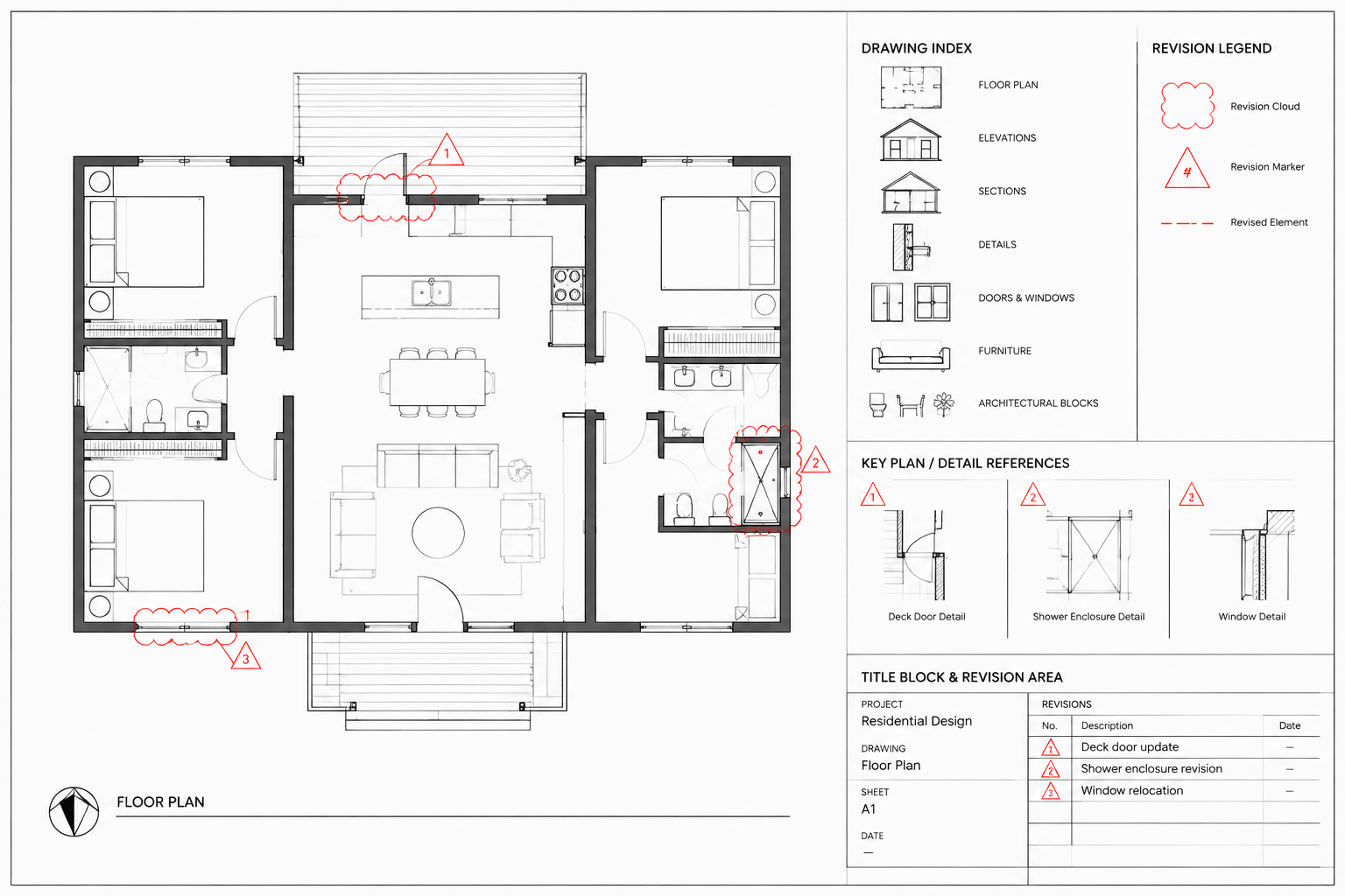
For example, a presentation-oriented plan may omit construction reference information that remains visible in a coordination view. An enlarged view may suppress broad plan annotation and display only notes relevant to the enlarged area.
Use viewport overrides selectively. A large number of unexplained overrides can make sheets difficult to troubleshoot because the model-space layer state no longer predicts the plotted result.
| Control | Appropriate use | Coordination concern |
|---|---|---|
| Viewport freeze | Hide a layer only in a particular sheet view | Important information can disappear from one viewport without affecting others |
| Viewport color override | Support a sheet-specific graphic hierarchy | Plot behavior should be checked with the project plotting method |
| Viewport linetype override | Differentiate reference or contextual information | Linetype appearance must be reviewed at the plotted scale |
| Viewport lineweight override | Refine emphasis for a specific view | Too many exceptions can undermine office standards |
When an override is necessary, make it part of the documented sheet setup rather than an invisible correction made immediately before plotting.
Coordinate annotation with viewport scale
Annotations may be placed in model space or paper space depending on the project workflow. Either method can work, but mixing methods without a clear rule often creates duplicated notes, inconsistent text sizes, and misplaced leaders.
Model-space annotation must account for how it appears through relevant viewports. If annotative objects are used, confirm that they support the scales at which they are expected to display. Paper-space annotation is naturally sheet-based but must remain aligned with the model content shown inside the viewport.
Whichever method is selected, test text, dimensions, symbols, and linework in a plotted or print-preview condition. A view that looks readable while zoomed in on screen may become crowded on the actual sheet.
Use clipped or irregular viewports carefully
Nonrectangular or clipped viewports can help fit a plan around notes, adjacent views, or sheet graphics. They are especially useful when the relevant building area has an irregular outline.
However, complicated boundaries can hide information unexpectedly and make selection more difficult. Avoid decorative shapes. The clipping boundary should follow a clear graphic reason, preserve the drawing’s readability, and leave space for associated dimensions and callouts.
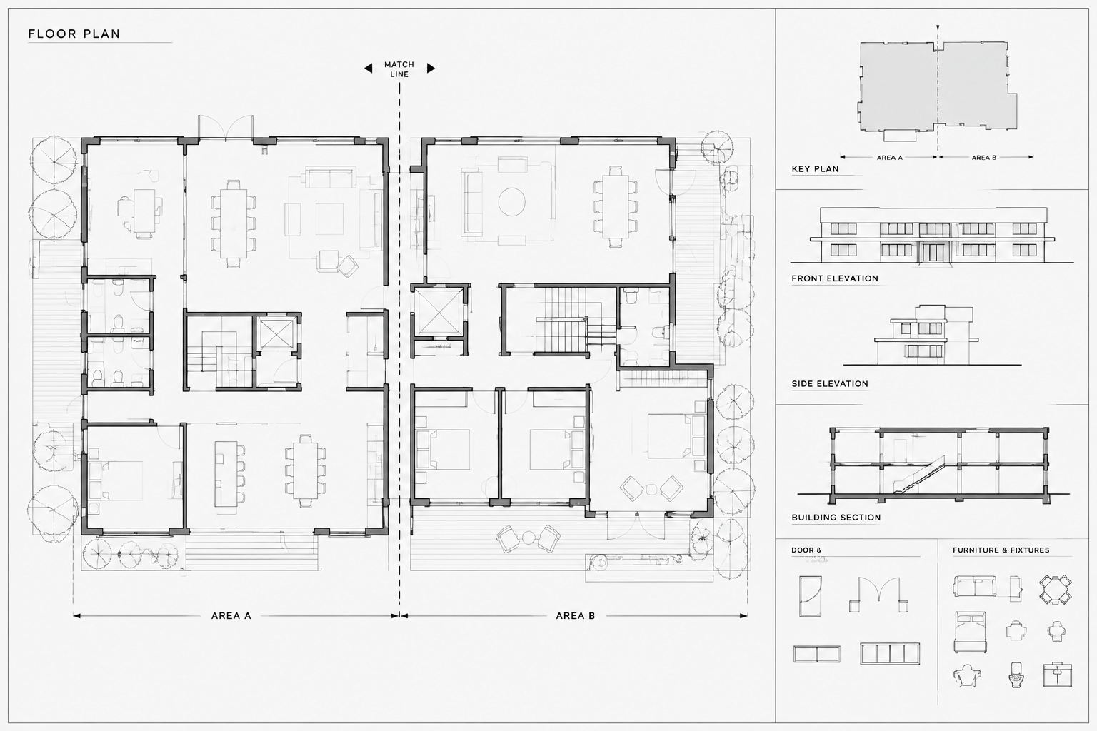
When two viewports show adjoining parts of a large plan, coordinate them as split views. Match lines, view references, orientation, scale, and overlapping context should guide the reader from one sheet area to the next.
Adopt consistent viewport naming and organization
Viewport objects are easy to overlook because they often do not plot. A simple office workflow can still make them manageable:
- Use one designated layer for primary viewport boundaries.
- Separate temporary working viewports from issued sheet viewports when needed.
- Keep general plans aligned consistently across related sheets.
- Place drawing titles in a repeatable relationship to their viewports.
- Lock completed viewports and include lock status in sheet checks.
- Review viewport-specific layer settings before issue.
Named model views can also help teams return to repeatable locations and orientations. They should support viewport setup rather than replace the final review of scale, framing, and sheet composition.
Final viewport quality-control checklist
Before plotting or publishing a sheet, inspect each viewport individually:
- Does the viewport show the intended model area?
- Is its scale correct and consistent with the drawing title?
- Is the view orientation coordinated with related drawings?
- Is the display locked?
- Are viewport boundaries set to plot or not plot as intended?
- Are required layers visible and unrelated layers suppressed?
- Have viewport-specific overrides been reviewed?
- Are notes, dimensions, tags, and symbols legible at sheet size?
- Are important elements being cut off by the boundary?
- Do match lines, section marks, elevation references, and detail callouts point to the correct destinations?
Finish with a whole-sheet review rather than checking viewports only in isolation. Balanced spacing, aligned titles, clear hierarchy, and consistent orientation make separate views read as one coordinated architectural document. When viewport setup is treated as a controlled drafting process, sheets remain more stable through revisions and easier for other team members to audit.