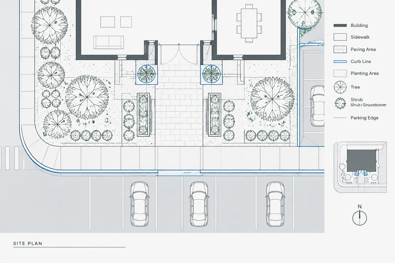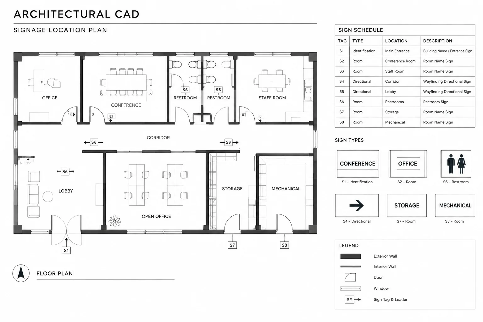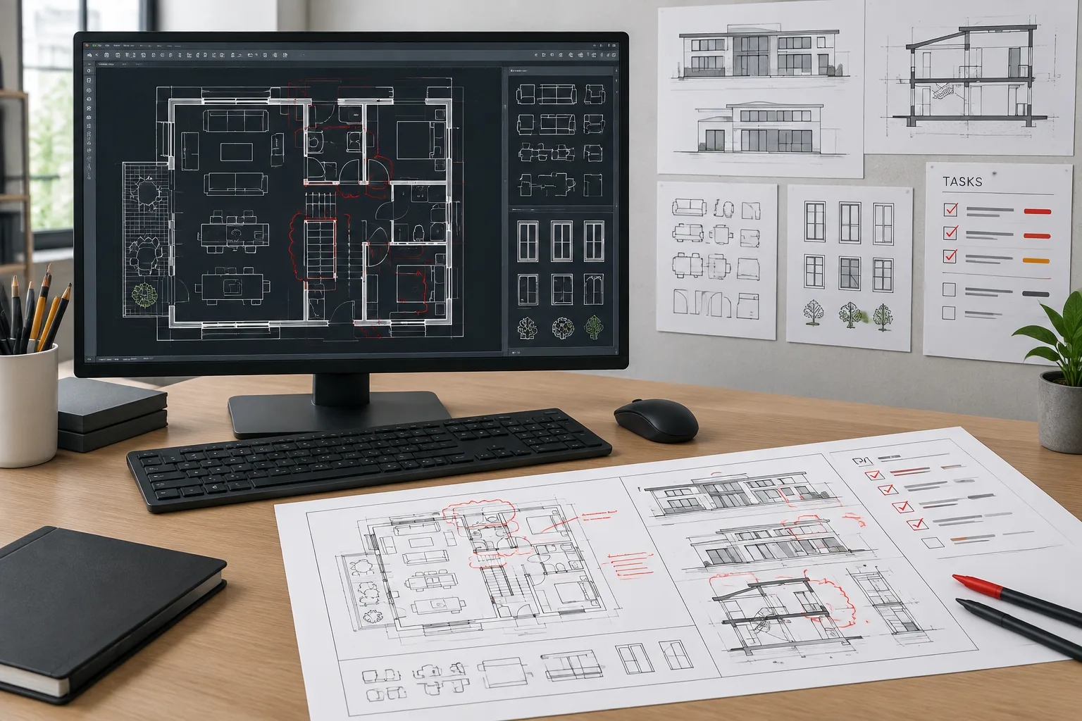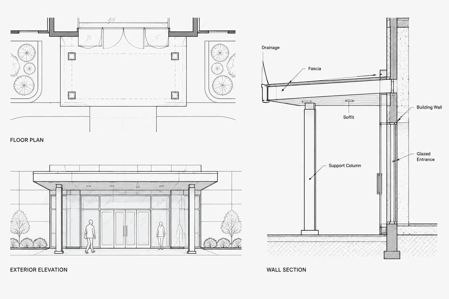
An operable partition is not simply a movable wall symbol. It is a coordinated architectural element whose operating path, storage condition, overhead track, surrounding finishes, and nearby building components must agree across the drawing set.
This guide explains how to develop operable partition CAD documentation without treating generic block geometry as verified construction information. It focuses on drawing controls, open and closed conditions, sheet coordination, and the clear identification of product-dependent details that remain unresolved.
Operable partitions allow one large room to be divided into smaller spaces, but their architectural CAD representation requires more than drawing a folding line across a floor plan. The partition may affect wall pockets, ceiling tracks, floor finishes, lighting, sprinklers, structure, controls, furniture layouts, and room identification. If these relationships are not coordinated, the drawings can show a partition that appears workable in plan but conflicts with the building above, below, or beside it.
A clear operable partition CAD workflow should communicate three basic conditions: where the partition runs when deployed, where its panels are stored when open, and what building elements support or surround the system. The drawings should also distinguish verified project information from diagrammatic placeholders that still require product and consultant coordination.
Begin with the operating concept
Before developing detailed graphics, determine how the space is intended to function. An operable partition may consist of individually movable panels, paired panels, or another project-specific configuration. Panels may stack at one end, divide between both ends, or move into a dedicated pocket. Do not assume the operating pattern from a generic CAD block.
Confirm the following design inputs with the project team and selected manufacturer information:
- The partition centerline and full deployed extent
- The proposed panel movement and stacking direction
- The location and approximate envelope of the stored panels
- Whether a wall pocket, closure panel, or exposed stack is intended
- The relationship between the overhead track and supporting construction
- Required access to controls, locks, seals, or service components
- Finish expectations for the panels, pocket doors, and adjacent walls
At an early design stage, some of these items may remain unresolved. Show enough information to reserve space, but label unverified components as diagrammatic or subject to manufacturer coordination rather than presenting them as final construction geometry.
Establish a reliable CAD reference line
Use a consistent reference line for the partition path. Depending on the office workflow, this may be the partition centerline, track centerline, or another clearly defined control line. The same reference should align through the floor plan, reflected ceiling plan, enlarged plan, elevation, and section.
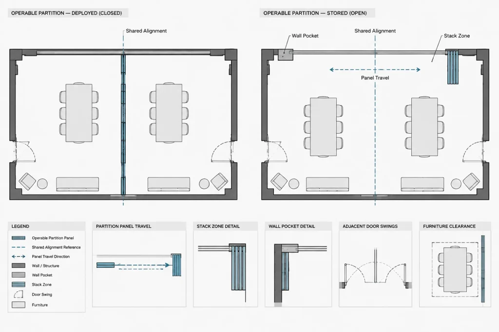
Place permanent room geometry first, including surrounding walls, columns, doors, glazing, and fixed casework. Then draw the operable partition route as controlled geometry rather than as a collection of unrelated line segments. A polyline can be useful for a straight or segmented path because it is easier to review for gaps and misalignment.
Avoid tracing the partition independently in every drawing. Where practical, derive enlarged views from the coordinated plan background or use externally referenced geometry so that a plan adjustment does not leave the ceiling track and elevation in an obsolete location.
Show deployed and stored conditions clearly
Deployed condition
In the primary floor plan, show the closed or deployed partition condition using graphics that remain legible at the intended plot scale. The linework should communicate the panel plane without competing with permanent walls. Add a concise tag or note identifying the element as an operable partition and reference an enlarged view, elevation, section, or specification location when those drawings exist.
Door swings and circulation paths should be checked in both room configurations. A nearby door that works when the partition is stored may conflict with the end closure or panel path when it is deployed. Furniture arrangements should also be reviewed for each operating condition rather than only for the combined room.
Stored condition
The panel stack is a three-dimensional object and should not be represented as a single symbolic mark without checking its actual envelope. Show the anticipated stack zone, pocket, or storage bay in plan. Use a contrasting linetype or a separate layer if both open and closed positions appear in the same view.
If the panels store inside a wall pocket, coordinate the pocket with framing, wall thickness, base, finishes, outlets, controls, and adjacent doors. The pocket entrance and any closure doors should be visible in the enlarged plan. If the stack remains exposed, verify that it does not obstruct circulation, casework, equipment, or required access.
Coordinate every affected drawing type
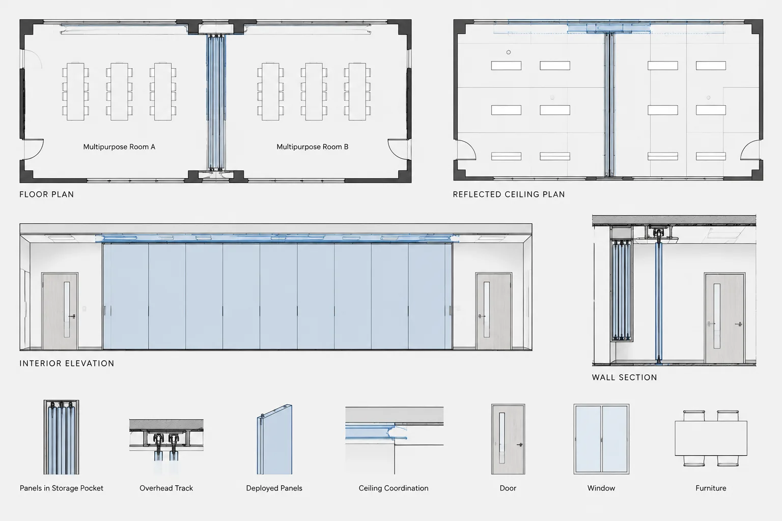
| Drawing | Information to show or verify |
|---|---|
| Overall floor plan | Partition location, room relationship, identifying tag, and basic deployed condition |
| Enlarged plan | Panel route, stack envelope, pocket geometry, end conditions, nearby doors, and finish transitions |
| Reflected ceiling plan | Track path, ceiling interruptions, lighting, diffusers, sprinklers, access panels, and ceiling pattern relationships |
| Interior elevation | Panel appearance, head condition, end closures, adjacent wall finishes, controls, and pocket closure |
| Building section | Vertical relationship among partition, track, ceiling, plenum, support, and floor |
| Details | Project-specific head, jamb, pocket, floor, and finish interfaces based on verified information |
| Finish drawings | Flooring continuity, base termination, panel finish, and changes between divided spaces |
Resolve the ceiling and overhead support zone
The reflected ceiling plan is a critical coordination drawing for an operable partition. The track should align precisely with the plan reference, while ceiling grids, panels, clouds, soffits, lights, diffusers, sprinklers, speakers, and access panels should be reviewed around it.
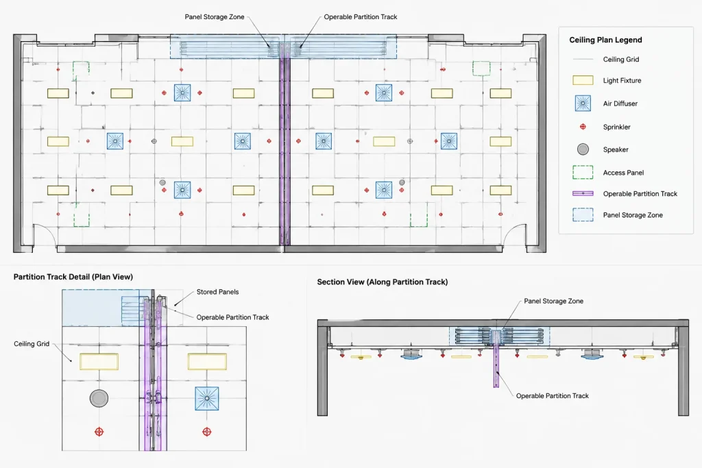
Do not imply that a suspended ceiling supports the partition unless the verified system and project design establish that relationship. Show the architectural intent for the track and ceiling interface, then coordinate the actual support with the structural team and manufacturer. The section should distinguish the visible ceiling condition from concealed support or bracing without inventing member sizes or connection details.
Consider maintenance and installation access as part of the drawing review. Even where access requirements are not yet known, avoid placing unrelated ceiling elements directly over the track or stack zone without coordination.
Develop elevations and sections from the same controls
An interior elevation should show how the deployed partition meets adjacent walls and how it appears within the room. Include permanent openings, ceiling features, base, wall finishes, and nearby controls so reviewers can understand the full composition. If a pocket closure is visible when the partition is deployed or stored, show both relevant conditions in separate views or clearly labeled diagrams.
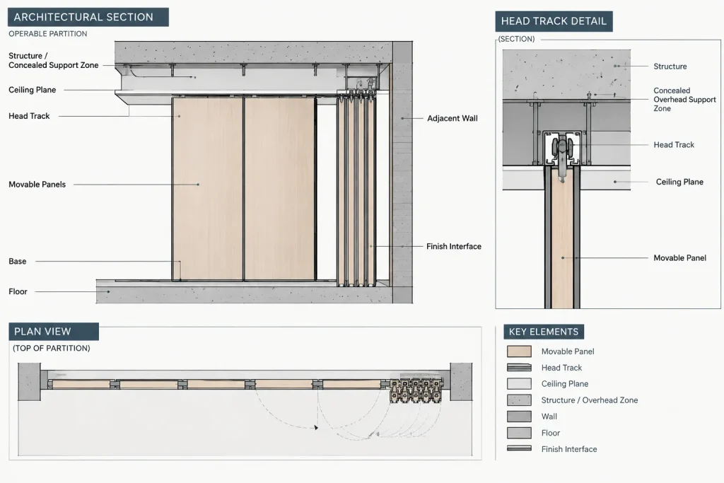
In section, identify the floor line, partition panels, head track, ceiling plane, and support zone. Use conventional break lines where concealed construction extends beyond the drawing area. The purpose of the section is to expose coordination relationships, not to reproduce a proprietary installation manual.
Generic details can establish drawing intent, but final interfaces should be revised after the selected assembly, wall construction, finishes, and structural support have been verified.
Use layers and blocks without hiding coordination problems
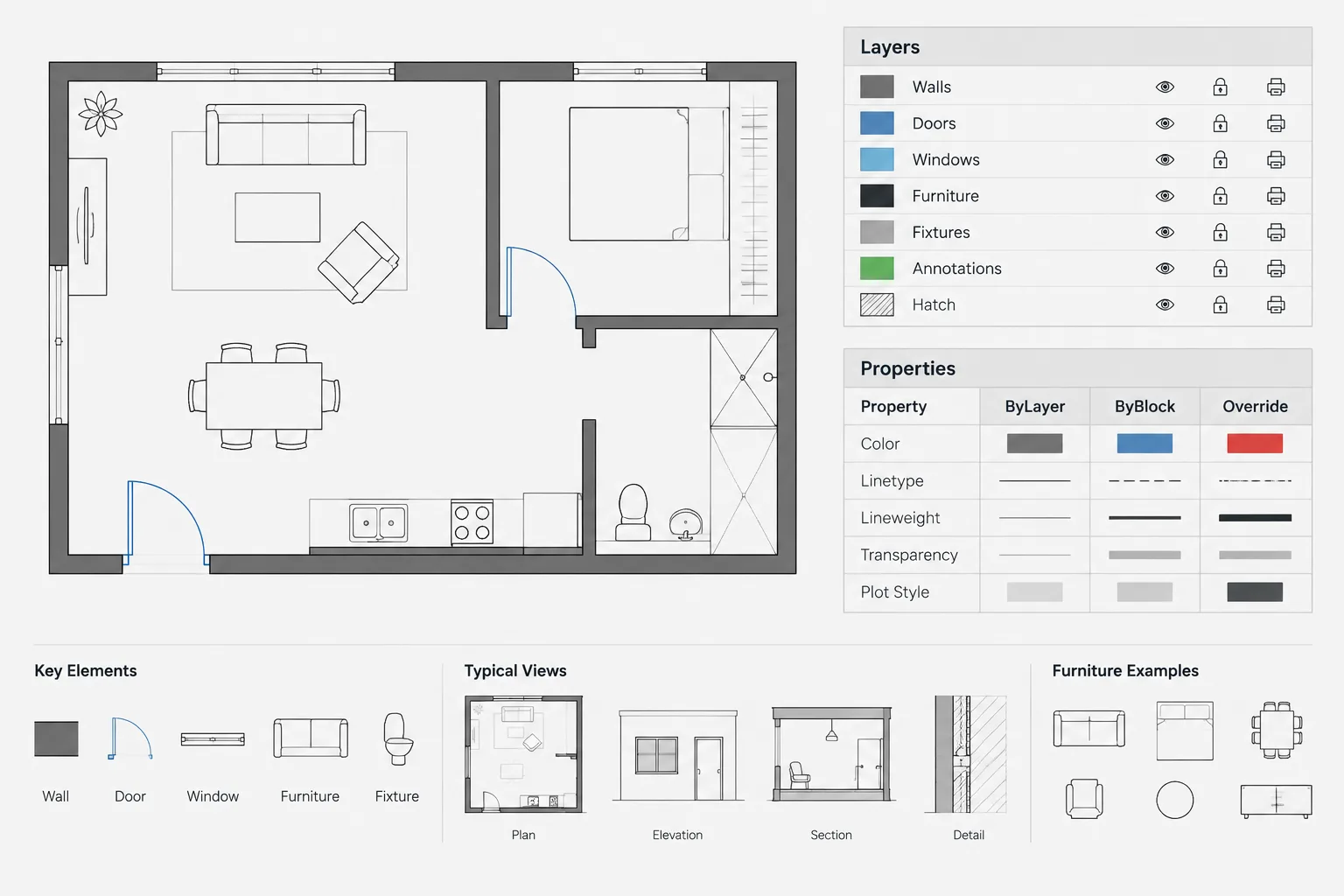
Separate layers can help distinguish the deployed partition, stored panels, overhead track, pocket, annotation, and optional operating diagrams. Clear layer naming is more useful than placing every component on a generic equipment or wall layer.
A block may be appropriate for a partition tag, control symbol, or simplified panel stack. Dynamic or adjustable block geometry can support early planning, but it should not imply that all systems use the same panel widths, stack depths, hardware, or clearances. Keep product-dependent geometry editable and replace placeholders when verified information becomes available.
If the operable partition appears on multiple sheets, use one coordinated source wherever the project workflow permits. Independently copied linework is likely to drift as the design changes.
Check room data and annotation in both configurations
A divisible room can create annotation questions. The combined space may have one room identity, while the divided condition may require separate names, numbers, finishes, occupancy assumptions, equipment, or operational notes. The appropriate approach depends on the project documentation strategy.
Keep room tags readable in each intended configuration and prevent them from overlapping the partition line. Coordinate finish designations and ceiling information so that the drawings do not contradict one another when the room is divided. Any acoustic, fire, accessibility, egress, or operational performance requirement should be confirmed by the responsible project professionals and supported by verified system information.
Run a focused coordination review
Before issuing the drawings, inspect the operable partition as a coordinated assembly rather than as an isolated plan symbol:
- Does the track centerline align across plans, ceiling plans, elevations, and sections?
- Is the full panel stack or pocket envelope shown?
- Can adjacent doors operate in both open and divided room conditions?
- Are furniture, equipment, and circulation kept clear of panel movement?
- Do ceiling fixtures or services conflict with the track and support zone?
- Are floor, wall, base, and ceiling finish transitions documented?
- Are controls and access points coordinated without unsupported assumptions?
- Do tags, notes, and detail references agree across sheets?
- Have generic placeholders been identified for later verification?
A successful operable partition drawing set makes movement, storage, and support understandable at a glance. By carrying one reliable control line through every relevant view and testing both deployed and stored conditions, the CAD drawings become a useful coordination tool rather than a symbolic indication that leaves major decisions unresolved.
Manage unresolved information without losing coordination
Operable partition information often develops as the architectural drawings progress. The location may be established before the panel configuration, stack arrangement, pocket construction, controls, or support details are confirmed. The CAD file should make that difference visible.
Keep the controlling partition path stable while placing product-dependent components on clearly identified layers or within editable placeholder geometry. Notes should distinguish verified project information from diagrammatic allowances. When manufacturer and consultant information becomes available, update the coordinated source rather than adding disconnected linework to individual sheets.
Review the partition as a drawing sequence
A useful review starts with the floor plan and follows the same partition reference into every related view. Confirm the deployed path and stored-panel envelope first. Then compare that geometry with the reflected ceiling plan, elevations, sections, finishes, room data, and adjacent equipment.
This sequence helps reveal mismatches that may be difficult to notice when sheets are reviewed independently. A track shown in the ceiling plan, for example, should not be accepted until its position agrees with the floor plan and its vertical relationship is understandable in section.
Keep the final CAD graphics easy to interpret
- Use consistent terminology for the partition, track, stack, pocket, and operating conditions.
- Give permanent construction, movable components, overhead elements, and annotations distinct graphic roles.
- Label simultaneous open and closed representations so they cannot be mistaken for duplicate construction.
- Use enlarged views where the overall plan cannot clearly communicate the stack, pocket, or end conditions.
- Remove obsolete placeholder geometry after verified information has been incorporated.
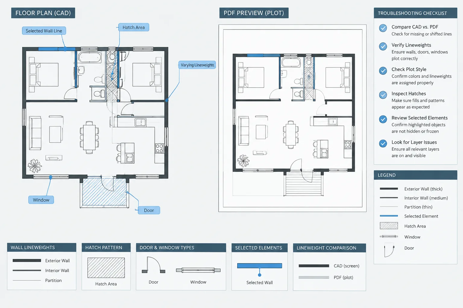
- Check plotted output so lineweights and linetypes remain understandable outside the CAD editing environment.
The objective is not to reproduce a proprietary system drawing. It is to create an architectural record that clearly communicates design intent, identifies pending coordination, and gives the project team a consistent basis for review.
Frequently asked questions
Should an operable partition be shown in both open and closed positions?
Show both conditions when they affect room use, circulation, furniture, adjacent doors, or storage space. They may appear in separate views or together with distinct layers, linetypes, and labels. The chosen method should prevent the stored panels from being mistaken for permanent construction.
Can a generic operable partition CAD block be used for construction documents?
A generic block can support early planning and diagrammatic coordination. It should not be treated as verified product geometry. Panel movement, stack arrangement, track interfaces, pockets, hardware, and access needs should be revised using confirmed project information.
What is the most important reference for coordinating the drawings?
Use a clearly defined control line, such as the partition or track centerline, and carry it consistently through plans, reflected ceiling plans, elevations, and sections. The drawing set should state or graphically establish what that line represents.
How should overhead support be represented?
Show the relationship among the partition, track, ceiling plane, plenum, and support zone without inventing concealed construction. Final support and connection information should follow verified manufacturer requirements and coordination with the responsible project professionals.
What should be checked around a wall pocket?
Review the pocket against adjacent framing, finishes, base, doors, outlets, controls, casework, and the full stored-panel envelope. The enlarged plan and relevant elevations or sections should explain how the pocket entrance and closure relate to the surrounding wall.
Should the track and panels use the same CAD layer?
Separate layers are generally more useful because the track, deployed panels, stored panels, pocket, and annotations may need different visibility or graphic treatment. Layer names should remain understandable to everyone working with the file.