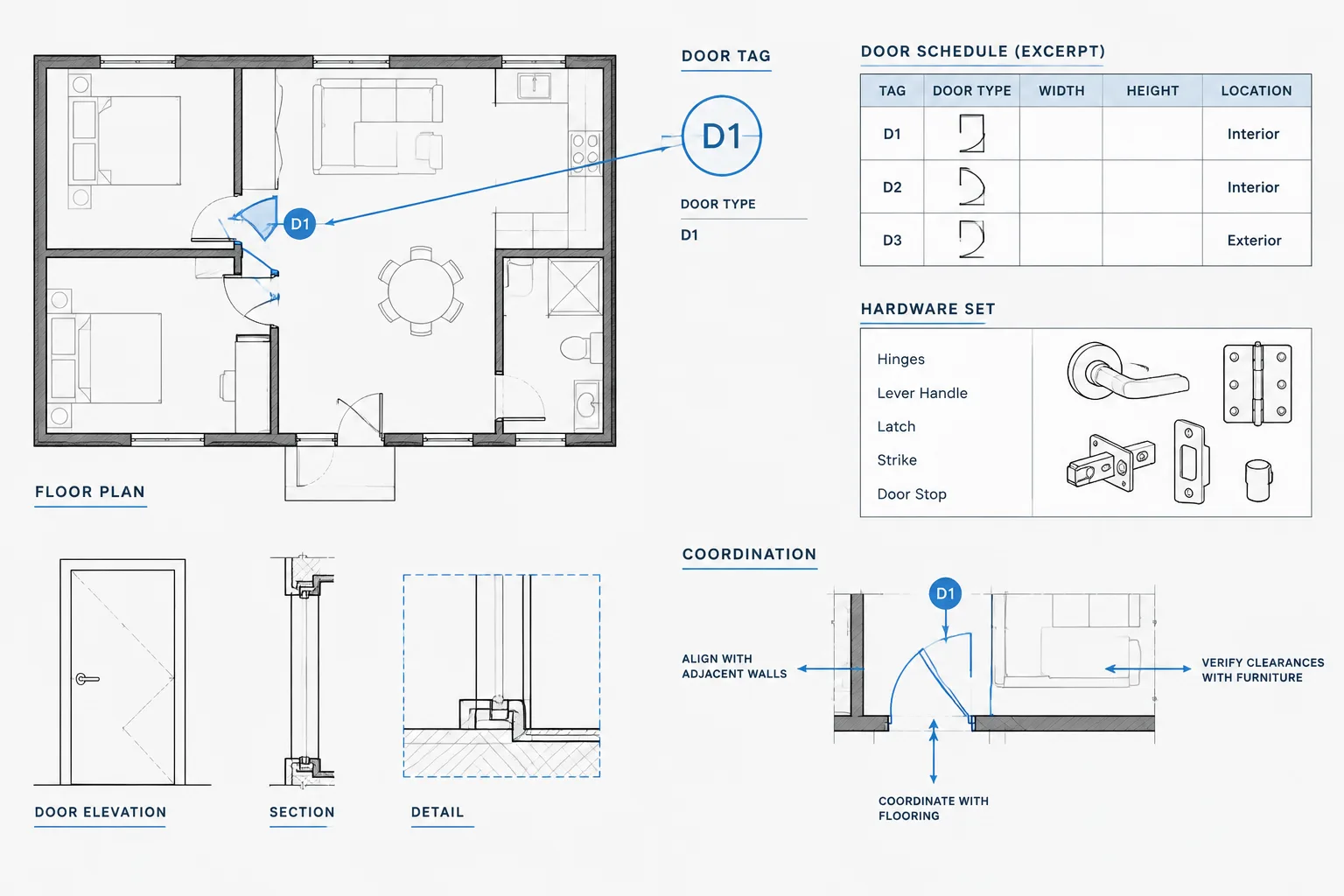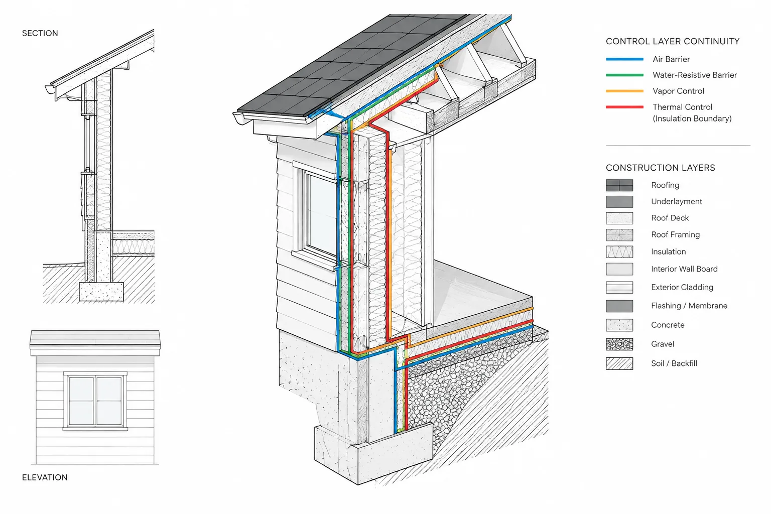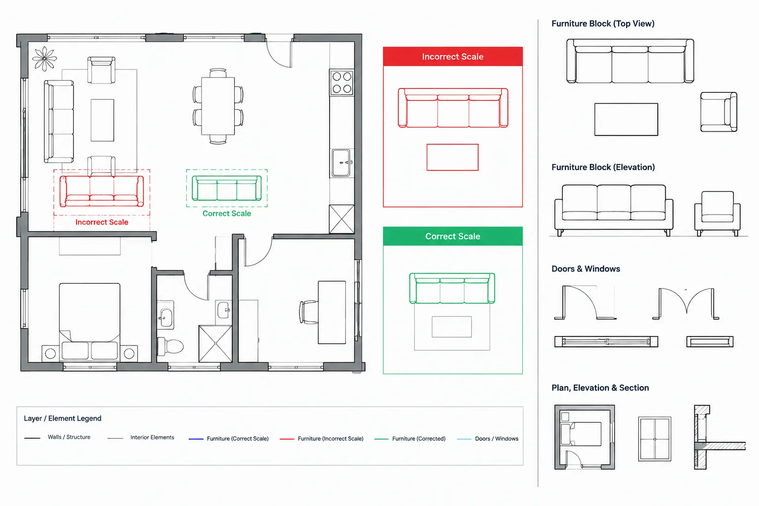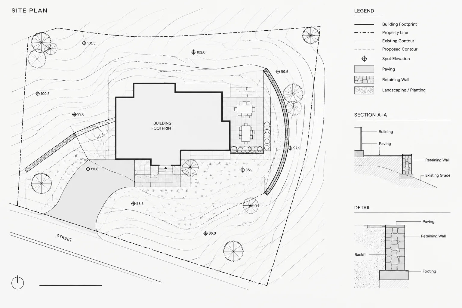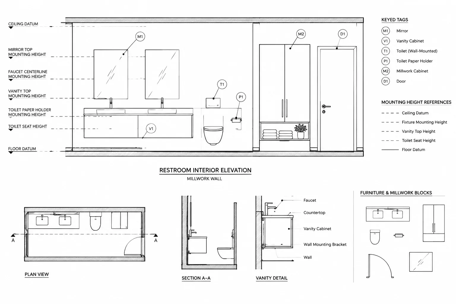
Mounting-height coordination is a drawing-management task as much as a dimensioning task. A clear vertical dimension can still cause problems when another sheet identifies a different location, uses another datum, or refers to a different part of the same object.
This guide explains how to establish reliable information sources, coordinate visible components with concealed rough-ins, manage repeated conditions, and review mounting data across plans, elevations, details, schedules, and consultant drawings.
Mounting heights appear throughout an architectural drawing set. They may define the location of wall-mounted fixtures, controls, accessories, equipment, signage, casework components, and specialty items. Although each note can look simple, coordinating many such requirements across multiple drawings is not.
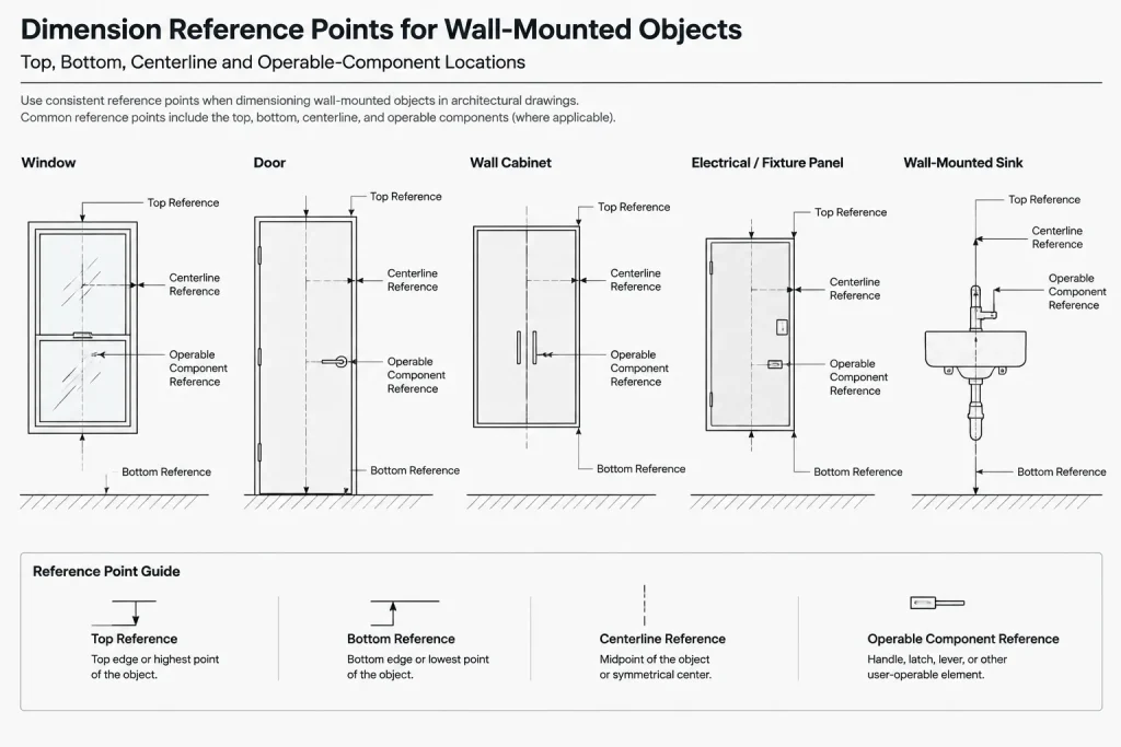
A mounting height shown on an interior elevation may conflict with a schedule, a consultant plan, or a manufacturer’s installation requirement. The reference point may also be unclear: a dimension might indicate the top, bottom, centerline, operating component, or rough-in location of an object. A reliable CAD workflow must therefore manage both the value and the meaning of each mounting-height dimension.
What a Mounting-Height Dimension Must Communicate
A useful mounting-height dimension identifies more than vertical distance. It should make the following information clear:
- The vertical datum from which the dimension is measured.
- The specific point on the object being located.
- Whether the dimension controls the finished item, rough-in, support, or connection.
- Whether the requirement is typical or unique to one location.
- Which drawing or schedule is the controlling source.
Labels such as “top,” “bottom,” “centerline,” and “operable part” are not interchangeable. Similarly, the centerline of a visible fixture may not match the centerline of its concealed electrical box or plumbing connection. If the distinction matters for installation, show or reference it directly.
Establish the Vertical Datum First
Most mounting heights are referenced to a finished floor or another clearly defined level. Before dimensioning, confirm that the architectural floor level is coordinated with the project’s elevation datums and finish information.
Conditions requiring additional attention include raised floors, platforms, curbs, shower bases, counters, stepped slabs, and areas with sloped flooring. A note that works in a typical room may become ambiguous where the finished surface changes beneath the mounted item.
Use consistent datum language throughout the set. Avoid switching casually between finished floor, structural slab, ceiling, countertop, and other references. If a non-floor datum is necessary, identify it beside the dimension or in the applicable detail.
Create a Source Hierarchy Before Drafting
Conflicts often occur because several drawings attempt to control the same item. Decide where mounting information will be maintained before adding dimensions across the project.
| Information source | Best use | Coordination concern |
|---|---|---|
| Interior elevation | Showing visible relationships among wall-mounted items | Can become crowded when every rough-in is dimensioned |
| Enlarged plan | Locating items horizontally and identifying wall conditions | Vertical information may be difficult to interpret in plan |
| Typical detail | Explaining repeated mounting, backing, or recess conditions | Exceptions must be identified separately |
| Schedule | Managing repeated item data in one organized location | Tags must match the plans and elevations |
| Consultant drawing | Defining discipline-specific rough-ins and connections | Architectural appearance and consultant requirements must agree |
| Manufacturer information | Confirming actual product geometry and installation needs | Selected products may change during design or construction |
A practical approach is to use interior elevations for visual placement, schedules for repeated data, and details for installation conditions. Consultant documents and verified product information should then be checked against those architectural sources.
Build a Mounting-Height Coordination List
Before detailing each room, create a project-specific list of items that require vertical coordination. The list may include bathroom accessories, mirrors, dispensers, wall cabinets, shelving, displays, signs, electrical devices, control panels, equipment, and specialty hardware.
For each item, record:
- Its drawing tag or identifier.
- The rooms or wall types where it occurs.
- The point being dimensioned.
- The intended datum.
- The primary information source.
- Related rough-ins, backing, blocking, recesses, or clearances.
- Any location that differs from the typical condition.
This list does not have to become a published schedule. It can serve as an internal coordination worksheet that helps the drafting team detect missing and contradictory information.
Draft the Wall Condition, Not Just the Object
A wall-mounted component should not be coordinated as an isolated CAD block. Its position may depend on casework, tile joints, wall panels, door swings, trim, mirrors, grab elements, countertops, and adjacent controls.
Begin with an accurate elevation of the wall. Show the floor line, ceiling or soffit where relevant, major finish boundaries, openings, casework, and fixed equipment. Then place the accessory or device in relation to those elements.
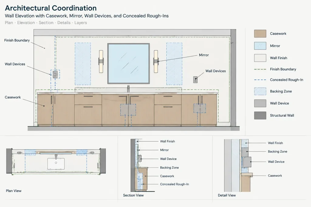
Check horizontal and vertical alignment intentionally. Items that appear aligned may use different functional reference points. For example, aligning the outlines of two devices does not necessarily align their controls, rough-ins, or usable portions.
Keep Symbolic and Actual Geometry Separate
Some plan symbols are intentionally enlarged or simplified for readability. Do not use symbolic plan geometry as the sole basis for tight installation coordination. Where the physical size matters, consult the selected product information or a verified generic envelope and show the relevant relationship in an elevation or detail.
Coordinate Architectural Items with Consultant Rough-Ins
Many wall-mounted objects require electrical, plumbing, communications, security, or mechanical connections. The visible component and concealed rough-in should be reviewed together, but they may not share the same centerline or elevation.
Overlay or reference the current consultant backgrounds and compare:
- Device tags and equipment identifiers.
- Wall and room locations.
- Connection points and service zones.
- Recess depths and wall construction.
- Access requirements.
- Conflicts with framing, structure, and casework.
Do not silently relocate consultant devices merely to improve the elevation composition. Mark discrepancies for coordination and update the appropriate source after the design team resolves them.
Use Typical Heights Carefully
Typical mounting requirements can reduce repeated annotation, but they should only be used when the underlying condition is genuinely repeated. A single typical note may fail where floor levels, counters, equipment models, or wall assemblies vary.
Identify exceptions visibly. An elevation can use a typical reference for common items while dimensioning unusual locations directly. Avoid publishing a general note that competes with more specific dimensions elsewhere in the set.
Code-related, accessibility-related, owner-required, and manufacturer-dependent locations must be verified for the actual project. A CAD library detail or block should be treated as a drafting reference, not as proof of compliance.
Organize CAD Layers and Blocks for Easier Checking
Separate mounted objects, annotations, dimensions, and consultant references according to the project’s layer system. This allows reviewers to isolate the information needed for coordination without hiding essential wall geometry.
Blocks can help maintain consistent graphics and tags, but avoid embedding an assumed mounting height into a block in a way that is difficult to detect. The block insertion point should support predictable placement, while the controlling height remains visible in a schedule, elevation, note, or property workflow used by the project team.
If a block contains text attributes, keep the attribute purpose clear. An item identifier is generally safer than free-form mounting data repeated independently in every block instance.
Check for Common Mounting-Height Errors
- Undefined reference point: The dimension reaches the object but does not state whether it controls the top, bottom, or centerline.
- Wrong datum: The note references a slab while the installer needs a finished-floor relationship.
- Duplicated values: Different heights are shown in an elevation, schedule, and consultant drawing.
- Ignored finish thickness: A recessed or surface-mounted item is coordinated to unfinished geometry.
- Uncoordinated product change: The specified component changes but its backing and rough-in remain based on earlier geometry.
- Overcrowded elevations: Dimension chains overlap tags, notes, and fixture outlines.
- Hidden exceptions: A typical note is applied to rooms with different counters, floors, or wall configurations.
Final CAD Review Workflow
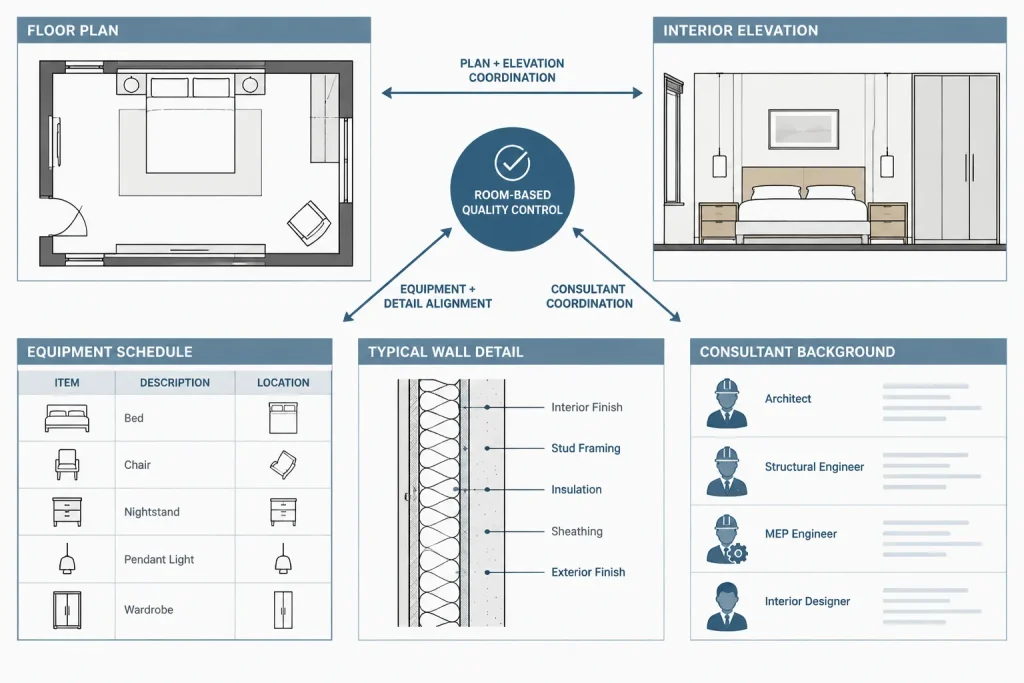
Review mounting heights room by room rather than sheet by sheet. A room-based check brings together the plan, elevations, details, schedules, and consultant information associated with the same physical space.
- Confirm the current architectural background and finished-floor datum.
- Identify every mounted item and its tag.
- Verify the dimension reference point for each item.
- Compare visible placement with related rough-ins and supports.
- Check adjacent doors, casework, finishes, and equipment.
- Resolve conflicting notes and remove redundant dimensions.
- Confirm that typical conditions and exceptions are clearly distinguished.
- Plot the sheet and review annotation at its intended output scale.
The goal is not to place as many dimensions as possible. It is to create one coordinated path from design intent to installation information. Clear datums, defined reference points, disciplined source control, and room-based review make mounting heights in architectural CAD easier to maintain and far less likely to conflict.
Document Coordination Decisions
When the project team resolves a mounting-height conflict, record the decision in the controlling drawing source rather than leaving it only in a markup, email, or meeting note. The corresponding elevations, schedules, details, and consultant references should then be reviewed for outdated information.
A simple coordination log can help track:
- The affected item and location.
- The drawings or schedules that disagree.
- The datum and object reference point under review.
- The discipline or team member responsible for confirmation.
- The source selected to control the final documentation.
- Related backing, rough-in, finish, or access changes.
This record is especially useful when products, room layouts, or wall assemblies change after drafting has begun. It gives reviewers a clear way to distinguish a resolved decision from an unresolved discrepancy.
Make Revisions Traceable
A mounting-height revision may affect more than the visible dimension. Check associated tags, leaders, block locations, schedule entries, detail references, backing notes, and consultant connection points. Moving only the graphic object can leave the documentation internally inconsistent.
Use the project’s established revision and quality-control process so that affected team members can identify what changed and where the controlling information now resides. Before issue, review the plotted sheets rather than relying only on the model-space view, because annotation conflicts and unclear leaders may become apparent only in the final drawing presentation.
What a Coordinated Result Looks Like
A coordinated drawing set gives the reader a direct path from an item tag to its location, datum, reference point, and installation relationship. Repeated information supports that path without creating competing instructions. When a condition differs, the exception is visible and connected to the correct room, wall, or item.
Frequently Asked Questions
Should a mounting height be measured to the top, bottom, or centerline?
Use the reference point that clearly controls the intended placement or operation of the item. Identify that point in the dimension, note, schedule, or detail rather than assuming the reader will infer it from the object outline.
Can a CAD block insertion point control the mounting height?
An insertion point can support consistent placement, but it should not conceal the design requirement. The controlling datum and reference point should remain visible in the project documentation and should be checked against the block geometry.
What should be done when an elevation and consultant drawing conflict?
Flag the discrepancy and determine which source should control through project coordination. Do not resolve it by silently moving the architectural object or consultant rough-in. After a decision is made, update every affected reference.
When is a typical mounting-height note appropriate?
A typical note is useful when the same item, datum, wall condition, and installation relationship genuinely repeat. Conditions affected by different floors, counters, finishes, products, or wall assemblies should be reviewed as possible exceptions.
Do manufacturer requirements replace architectural coordination?
Manufacturer information can define product geometry, supports, connections, and installation needs, but those requirements must still be coordinated with the room layout, finishes, wall construction, consultant work, and project documentation.
Why should mounting heights be reviewed by room?
A room-based review brings together the drawings that describe the same physical space. It makes conflicts among plans, elevations, schedules, details, casework, finishes, and consultant rough-ins easier to identify.