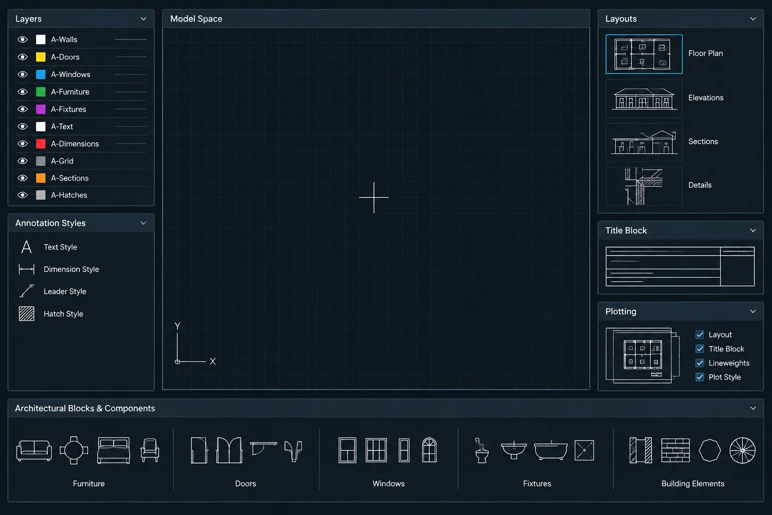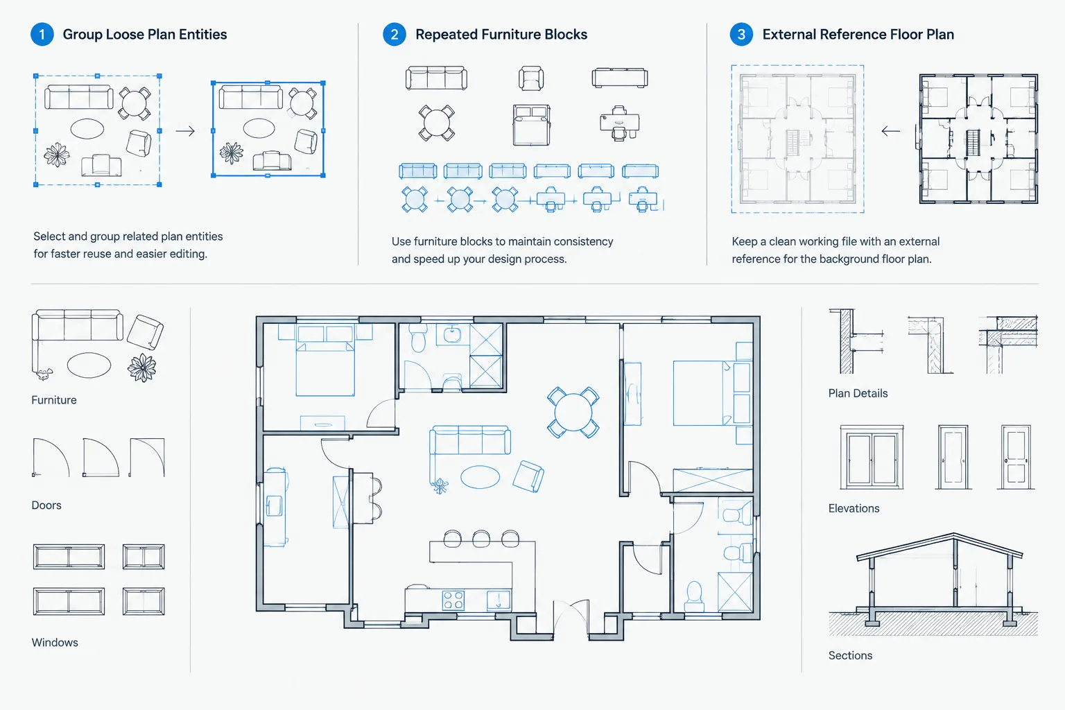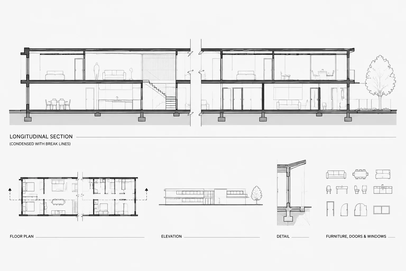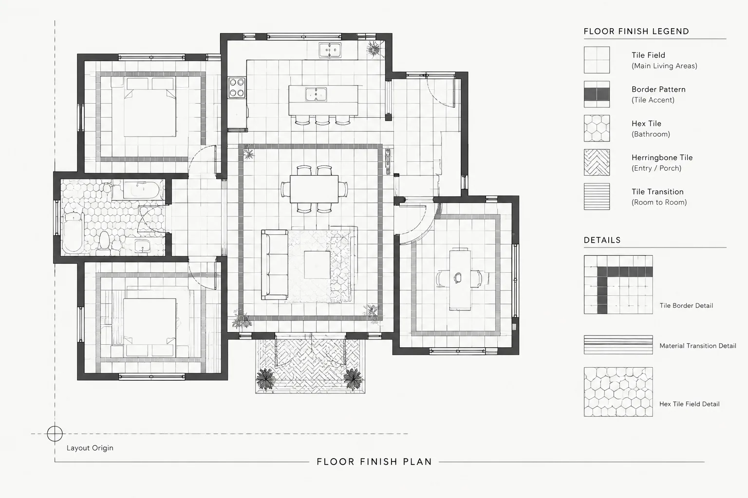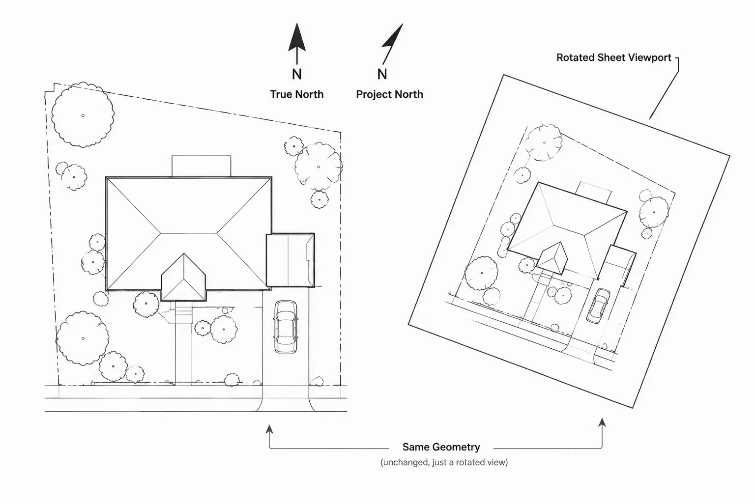
True north, project north, and view rotation solve different architectural CAD problems. True north connects the drawing to its geographic basis, project north provides a practical working orientation, and view rotation controls how coordinated geometry appears on screen or on a sheet.
The key is to avoid treating these orientations as interchangeable. Before changing an angle, determine whether the issue belongs to the project coordinates, the building setup, or only the presentation view. This distinction helps protect external-reference alignment while allowing plans to remain clear and readable.
North orientation can appear simple until a project combines a survey, a rotated building footprint, consultant backgrounds, and sheets arranged for readability. If each file handles orientation differently, plans may look correct while their coordinates, references, or annotations no longer align.
A reliable workflow separates three decisions: how the project relates to geographic north, how the building is oriented for drafting, and how each plan is presented on a sheet. Keeping those decisions distinct makes external references easier to manage and reduces accidental rotation of coordinated geometry.
Understand the Main Orientation Terms
True north
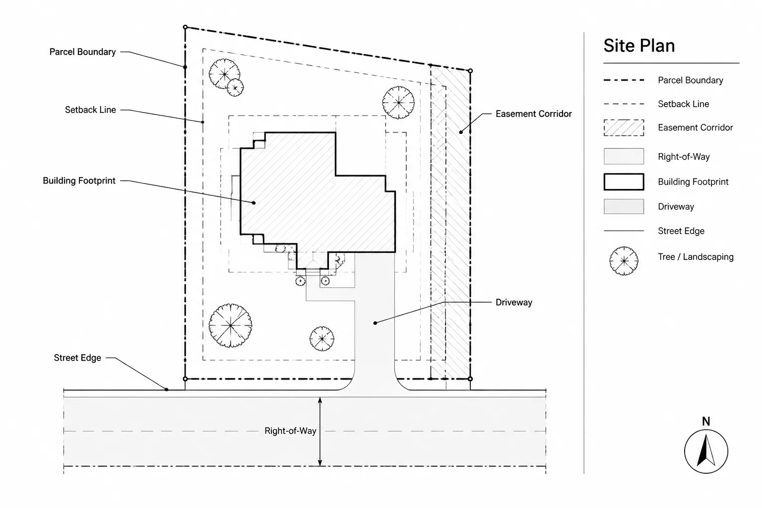
True north describes geographic direction. It is commonly established from survey or civil information rather than estimated from an aerial image, property shape, or drawing border. Site plans and other drawings that depend on geographic relationships may need to show true north clearly.
Project north
Project north is a working orientation selected to make the building easier to draft and read. A long building wing, major corridor, or structural grid may be treated as horizontal or vertical even when it is angled relative to true north.
Project north does not replace the survey orientation. It is a presentation and coordination convention that must remain traceable to the project’s geographic basis.
View or sheet orientation
A plan can be rotated inside a viewport so that it fits a sheet or reads more naturally. This is a view adjustment, not necessarily a change to the model geometry. Several sheets may present the same coordinated model at different orientations.
This distinction is important: rotating a view is usually reversible, while rotating actual model objects can affect coordinates, external references, dimensions, and consultant alignment.
Establish the Coordinate Basis Before Rotating Anything
Begin with the most reliable project information available, typically a verified survey, civil base, or agreed consultant control file. Identify the project origin, reference points, coordinate system, units, and north direction before building the architectural file structure around them.
Do not infer north from the way an imported drawing opens. A survey may have been clipped, rotated for presentation, or exported from another system. Confirm whether its coordinate geometry is intact and whether its north arrow refers to true north, another grid direction, or a sheet convention.
Record the orientation decision in a project CAD guide or drawing setup note. Team members should be able to answer these questions:
- Which file controls the site coordinates?
- Which direction represents true north?
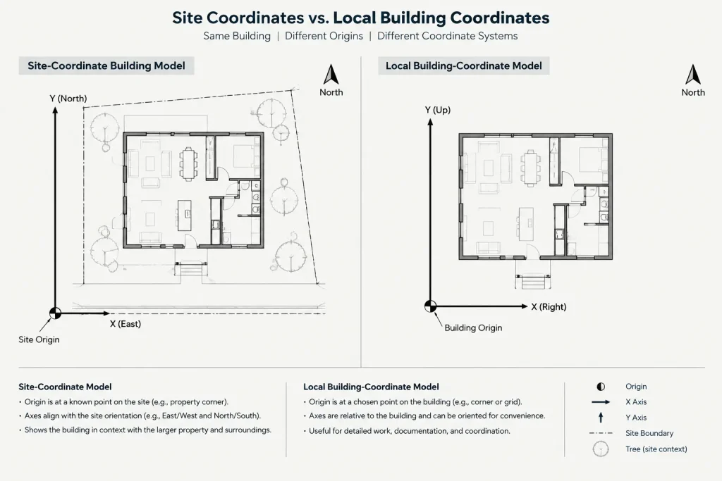
- Is the architectural model drawn in site coordinates or local building coordinates?
- How is project north defined?
- Are sheet plans rotated through views or through model geometry?
- Who may change the shared coordinate relationship?
Choose a Model Organization Strategy
Two general approaches are common. Neither should be adopted casually; the appropriate choice depends on the project’s consultant workflow and file structure.
| Approach | How it works | Main coordination concern |
|---|---|---|
| Site-coordinate model | Architectural geometry remains aligned with the established survey or civil coordinate basis. | Building plans may need rotated views for convenient drafting and sheet presentation. |
| Local building model | The building is drawn near a practical local origin and aligned with its primary grids or walls. | A controlled host or reference file must preserve the exact relationship between the building and the site. |
With a site-coordinate model, consultant references can often be attached using consistent coordinates. The tradeoff is that the building may appear angled in model space. Saved views, named coordinate systems, or rotated paper-space viewports can provide a comfortable working orientation without altering the source geometry.
With a local building model, architectural drafting can be straightforward, especially for orthogonal plans. However, the insertion point and rotation connecting that model to the site must be managed deliberately. Moving the building to make it fit another background can break the established relationship.
Rotate the View, Not the Coordinated Model
Once coordinated geometry is positioned correctly, avoid rotating it merely to improve sheet composition. Instead, control presentation through a saved view, an appropriate user coordinate system, or viewport orientation.
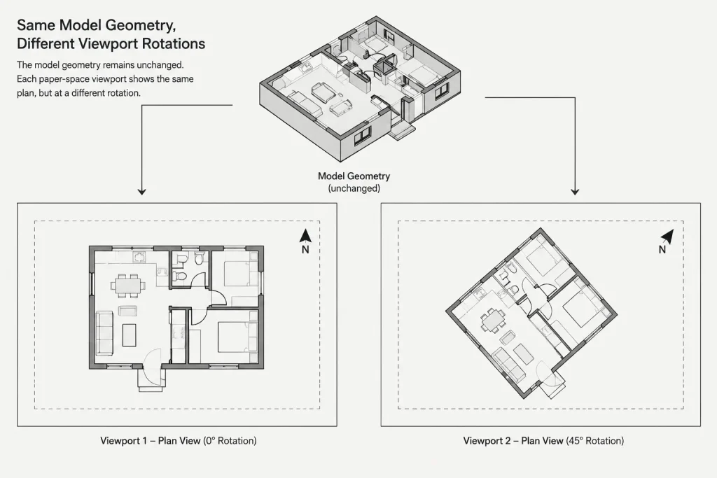
A practical sheet workflow is:
- Confirm that the model and its external references align in the agreed coordinate basis.
- Create a view that places the desired project direction upright on screen.
- Use that view within the paper-space viewport.
- Set the viewport scale and position.
- Lock the viewport after checking its orientation.
- Verify that dimensions, text, symbols, and callouts remain readable.
Be careful when changing the active coordinate system. A rotated coordinate system can make orthogonal drafting easier, but users must understand whether they are changing only the drawing axes, changing the displayed view, or transforming actual objects. Test the process in a controlled file before applying it across a live project.
Use North Arrows That Communicate the Intended Direction
A north arrow should identify what it represents. If true north and project north differ, an unlabeled arrow may create ambiguity. Depending on the drawing purpose and office conventions, a plan may show true north, project north, or both with distinct labels.
Create north arrows as managed CAD blocks rather than redrawing them on every sheet. The block should have a logical insertion point and a clearly understood default direction. Keep its text and linework on appropriate annotation layers so it plots consistently with the rest of the drawing.
A north arrow placed in paper space may be convenient for sheet control, but it must still correspond to the displayed viewport. Copying an arrow between sheets without checking viewport rotation is a common source of errors. A model-space symbol can maintain a direct relationship to geometry, although its plotted size and visibility require careful management. Choose one office method and apply it consistently.
Coordinate Rotated Plans with External References
External references should retain predictable insertion points, scales, and rotations. If a consultant background arrives at an unexpected angle, do not immediately rotate it by eye. First determine whether the file uses site coordinates, a local origin, or a separate presentation orientation.
When a local building model is referenced into a site host, document the controlled translation and rotation. Avoid applying slightly different placements in multiple files. A dedicated coordination host can provide one repeatable location for architecture, civil, structural, landscape, and other disciplines.
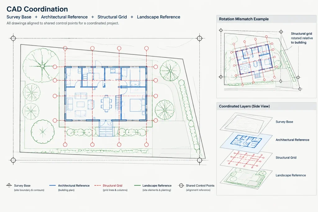
After updating an external reference, check more than visible wall alignment. Compare known control points, grid intersections, property features, building corners, and other stable references. A file can appear close while still containing a rotation or origin discrepancy.
Keep Annotation Independent from Accidental Rotation
Rotated plan views can expose annotation problems. Text may turn sideways, dimension strings may no longer read from the intended direction, and room tags may overlap geometry after viewport changes.
Decide whether annotation belongs in model space or paper space according to the project workflow. If model-space annotation must appear in differently rotated views, configure and test its orientation behavior rather than assuming every object will remain readable. If annotations are view-specific, organize them so notes intended for one rotated plan do not appear in another.
Callouts and elevation markers also need review. Their directional meaning should relate to the building, while their text should remain legible on the sheet. Do not rotate an entire annotation set as a shortcut without checking what each symbol communicates.
Common Orientation Mistakes
- Rotating the survey to make the building horizontal: This can destroy the relationship to geographic coordinates unless performed as part of a documented setup.
- Assuming the top of every plan is north: Sheet composition may place north in another direction.
- Using an unlabeled north arrow: Readers may not know whether it represents true north or project north.
- Rotating nested references independently: Different placements can create conflicting versions of the same base information.
- Copying viewports without checking orientation: The viewport, north arrow, match lines, and annotations may no longer agree.
- Changing the coordinate basis during production: Uncontrolled changes can affect every linked discipline and issued sheet.
Orientation Quality-Control Checklist
- Confirm the authoritative survey or site control file.
- Verify units, origin, control points, and true-north direction.
- Document whether the building model uses site or local coordinates.
- Confirm the relationship between true north and project north.
- Check that external references share the intended insertion and rotation.
- Use saved views or viewport rotation instead of rotating coordinated geometry for presentation.
- Lock completed viewports.
- Verify north arrows against the actual displayed view.
- Review text, dimensions, tags, and directional symbols on every rotated plan.
- Recheck control points after receiving updated consultant backgrounds.
A Clear Orientation Strategy Protects the Whole Drawing Set
North orientation is not just a graphic choice. It connects survey data, building geometry, external references, plan readability, and sheet annotation. The safest workflow establishes one reliable coordinate basis, documents the relationship between true north and project north, and uses view controls for presentation whenever possible.
When geometry and presentation are managed separately, plans can be rotated for clarity without weakening consultant coordination. That separation also makes future updates easier to diagnose: the team can determine whether an issue belongs to the model coordinates, the project orientation, or only the sheet view.
A Practical Way to Diagnose Orientation Problems
When a plan appears incorrectly rotated, start by identifying what is actually wrong. A geographic problem concerns the survey basis or true-north direction. A coordination problem concerns the placement of the architectural model and its references. A presentation problem concerns only how the plan is displayed in a viewport or saved view.
- Check the geometry: Compare stable control points before evaluating sheet appearance.
- Check the references: Confirm that linked files use the agreed origin, scale, and rotation.
- Check the view: Determine whether the display has been rotated independently of the model.
- Check the annotation: Review north arrows, dimensions, tags, callouts, and match lines in the final sheet orientation.
This sequence prevents a presentation issue from being “fixed” by moving coordinated objects. It also gives project teams a clearer way to report problems: instead of saying that a plan is rotated, they can identify whether the discrepancy is in the model, the reference placement, or the viewport.
Document Orientation Changes as Coordination Changes
Any adjustment that changes the relationship between the building and the site should be treated as a coordinated project decision. Record what changed, which file controls the relationship, and which dependent backgrounds or sheets require review. A viewport adjustment may need only a sheet check, while a model-placement change can affect every discipline using that geometry.
For handoffs, include enough setup information for another CAD user to reconstruct the intended relationship without rotating files by eye. The receiving user should be able to identify the control file, distinguish true north from project north, and understand whether the delivered plan is shown in its coordinate orientation or through a rotated view.
Frequently Asked Questions
Is project north the same as true north?
No. True north represents geographic direction, while project north is a working orientation selected to make the building easier to draft and read. Their relationship should remain documented and traceable.
Does rotating a viewport change the model coordinates?
A view or viewport rotation is intended to change presentation rather than transform the coordinated model geometry. Users should still verify the result because moving objects, changing reference placement, and rotating a view are different operations.
Should a survey be rotated to match the building?
Not merely for drafting convenience. First confirm the survey’s coordinate basis and north direction. If the building needs a more convenient working orientation, use an approved model-organization strategy or rotate the view without casually altering the survey geometry.
Why can an external reference look aligned but still be incorrect?
Nearby geometry can appear visually close even when the reference has an origin or rotation discrepancy. Check known control points, grid intersections, property features, and other stable references rather than relying only on wall alignment.
Should a north arrow be placed in model space or paper space?
Either method can be used within a controlled office workflow. A paper-space arrow must be checked against the viewport orientation, while a model-space arrow requires careful control of plotting and visibility. Consistency and verification are more important than choosing a method by habit.
What should be checked after rotating a plan view?
Review the north arrow, text, dimensions, room tags, callouts, elevation markers, match lines, viewport position, and external-reference alignment. Confirm that the sheet remains readable without changing the underlying coordinated geometry.