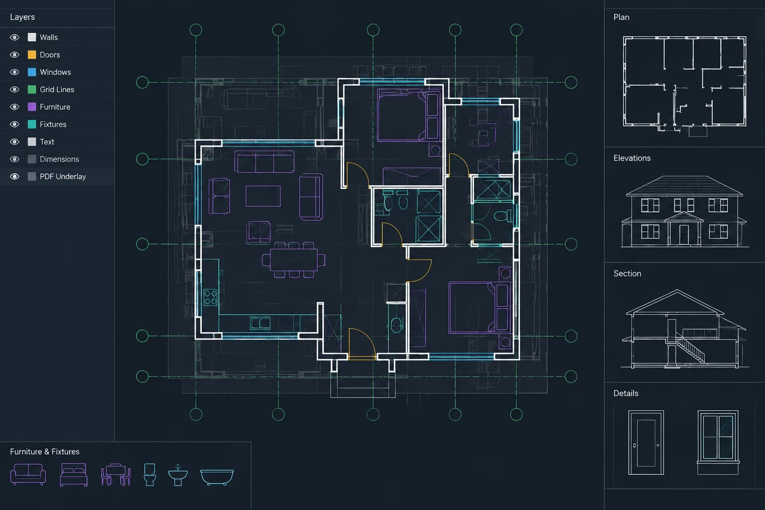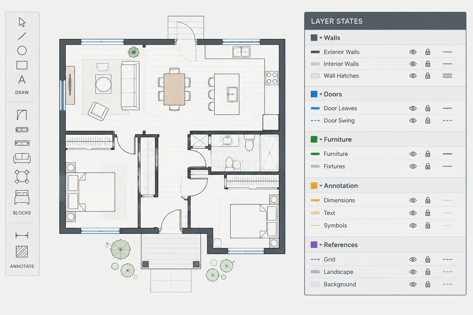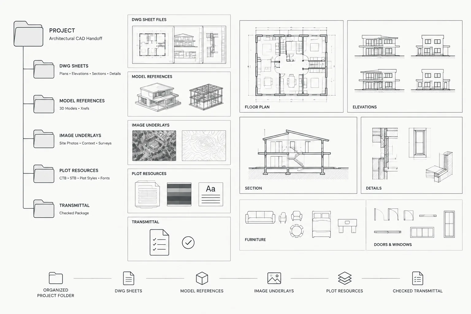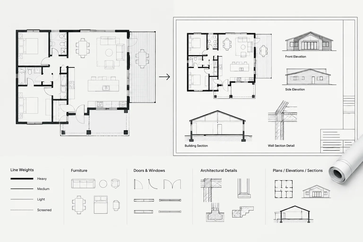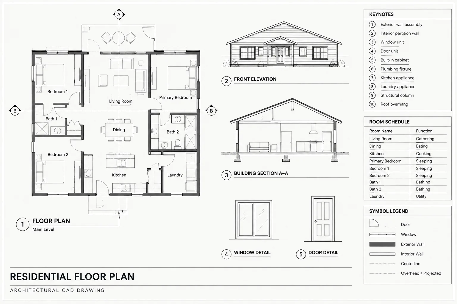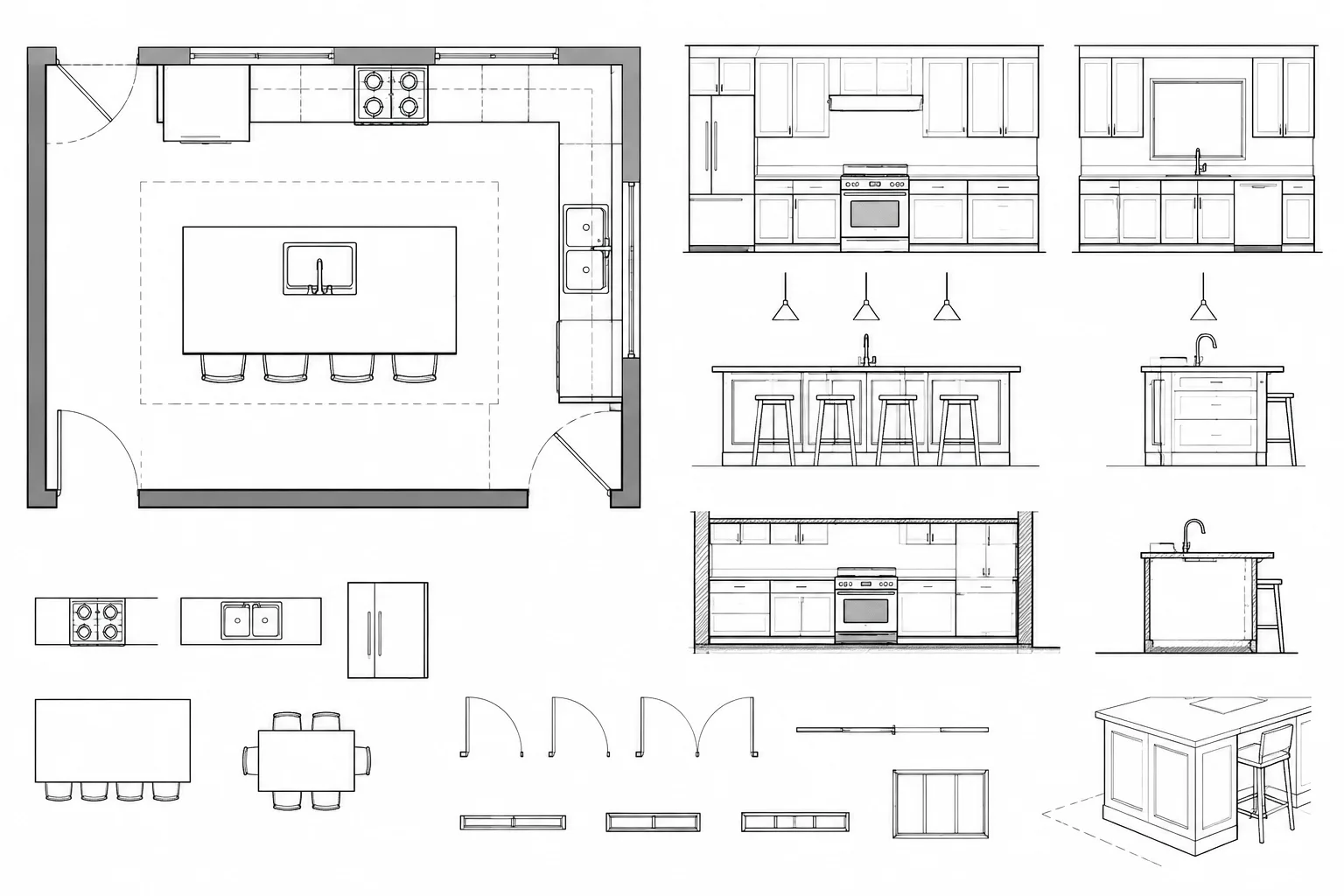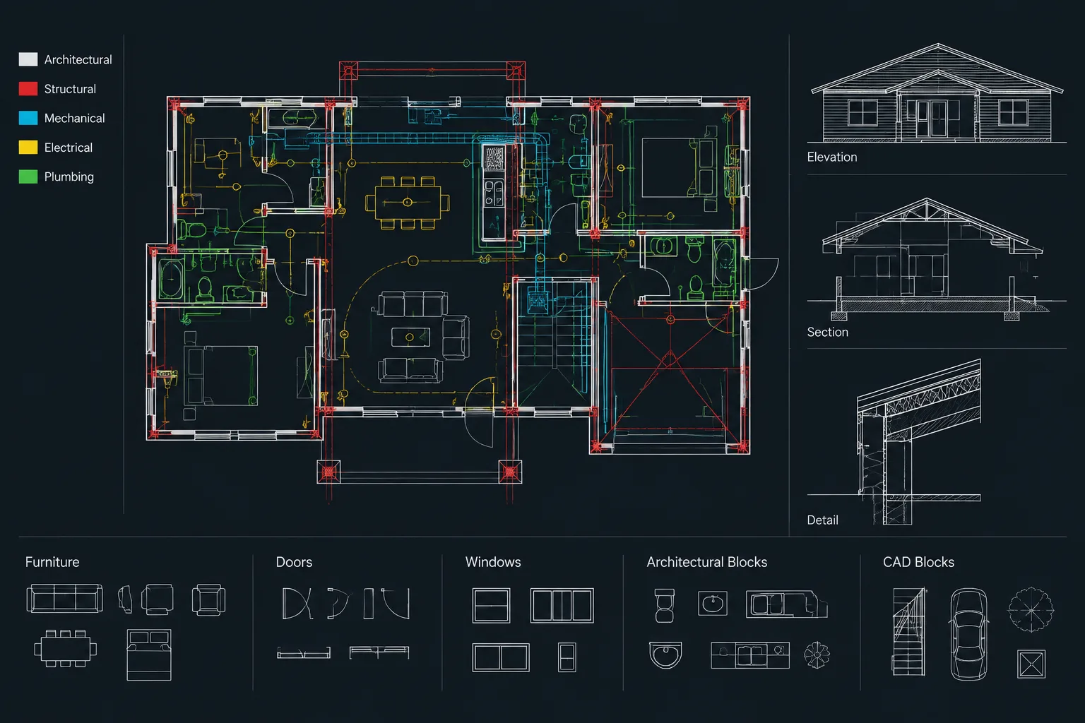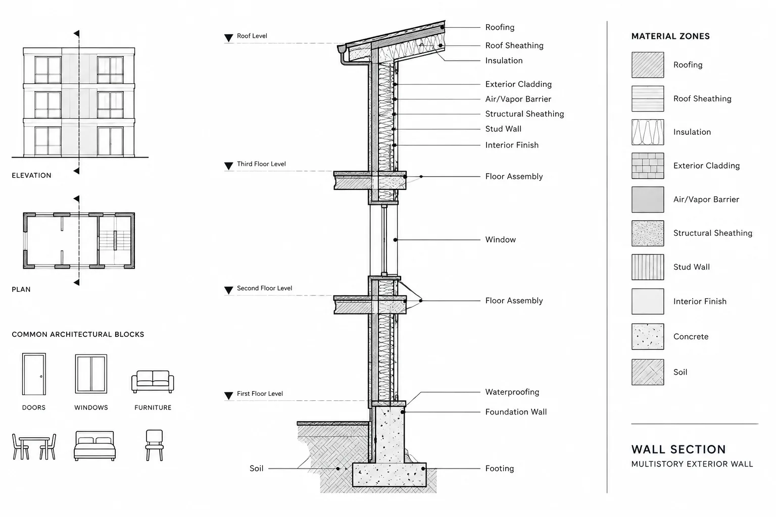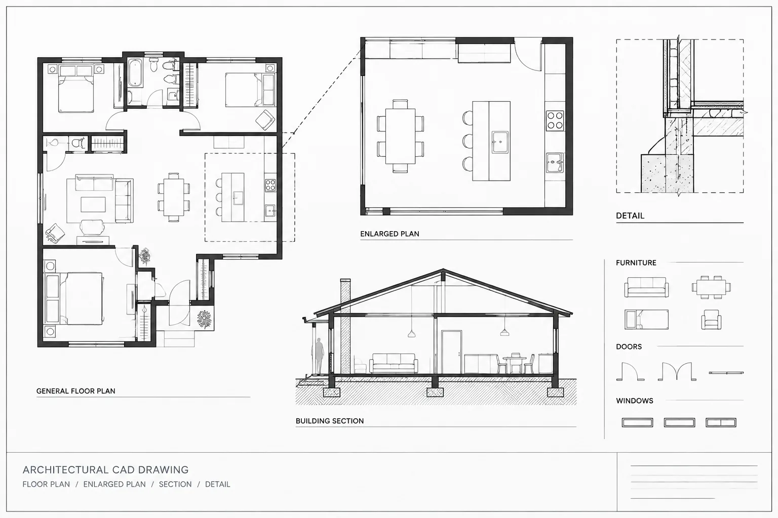
Architectural CAD drawing scales work as information filters. A scale that is appropriate for an overall plan may be unable to support the dimensions, fixture layouts, notes, and references needed for a concentrated area.
This guide presents a purpose-based method for selecting and checking scale. Rather than relying on habit, it considers the view’s role, available sheet space, annotation density, relationship to other drawings, and appearance in the final output.
Choosing a drawing scale is not simply a matter of fitting geometry onto a sheet. Scale determines what information can be shown clearly, how much annotation a view can support, and whether the drawing communicates its intended purpose when printed or viewed as a PDF.
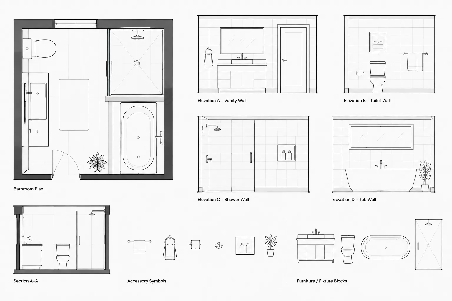
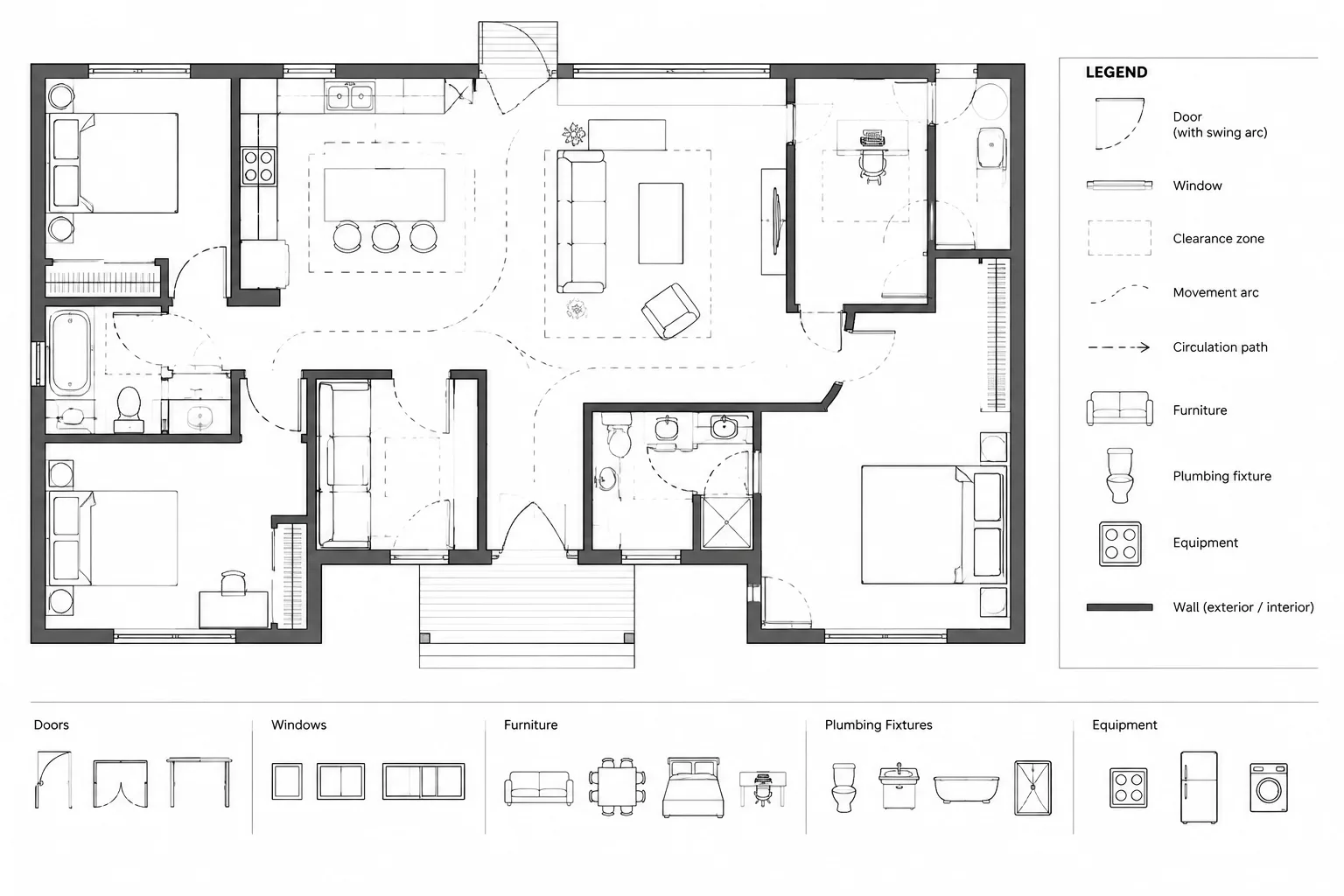
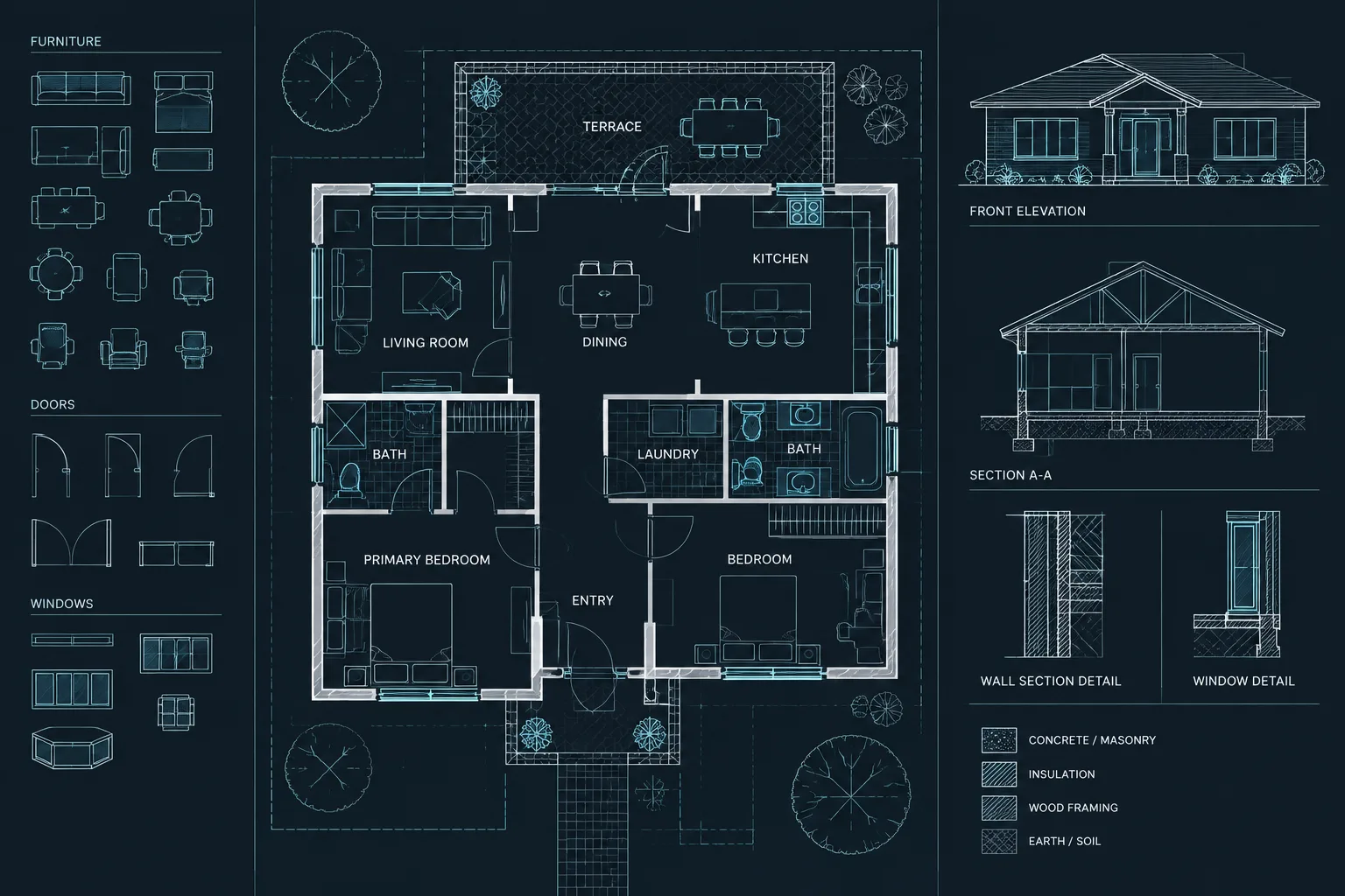
In a well-organized architectural CAD set, related views may use different scales because they answer different questions. A general floor plan explains overall arrangement and circulation, while an enlarged plan may clarify doors, fixtures, partitions, and dimensions in a concentrated area. A detail provides an even closer look at an assembly or connection. The correct scale is therefore the one that supports the required information without making the sheet crowded or fragmented.
Begin with the purpose of the drawing
Before creating a viewport or selecting a scale, define what the view needs to communicate. A drawing intended to show the overall building should not be expected to carry the same amount of information as a room enlargement or construction detail.
Architectural views generally fall into several communication levels:
- Orientation views establish the location, overall form, major zones, or relationship to the site.
- General arrangement views show rooms, circulation, openings, primary dimensions, and major building elements.
- Enlarged views explain areas where fixtures, equipment, clearances, finishes, or partitions require closer coordination.
- Elevations and sections communicate vertical relationships, heights, materials, openings, and assemblies.
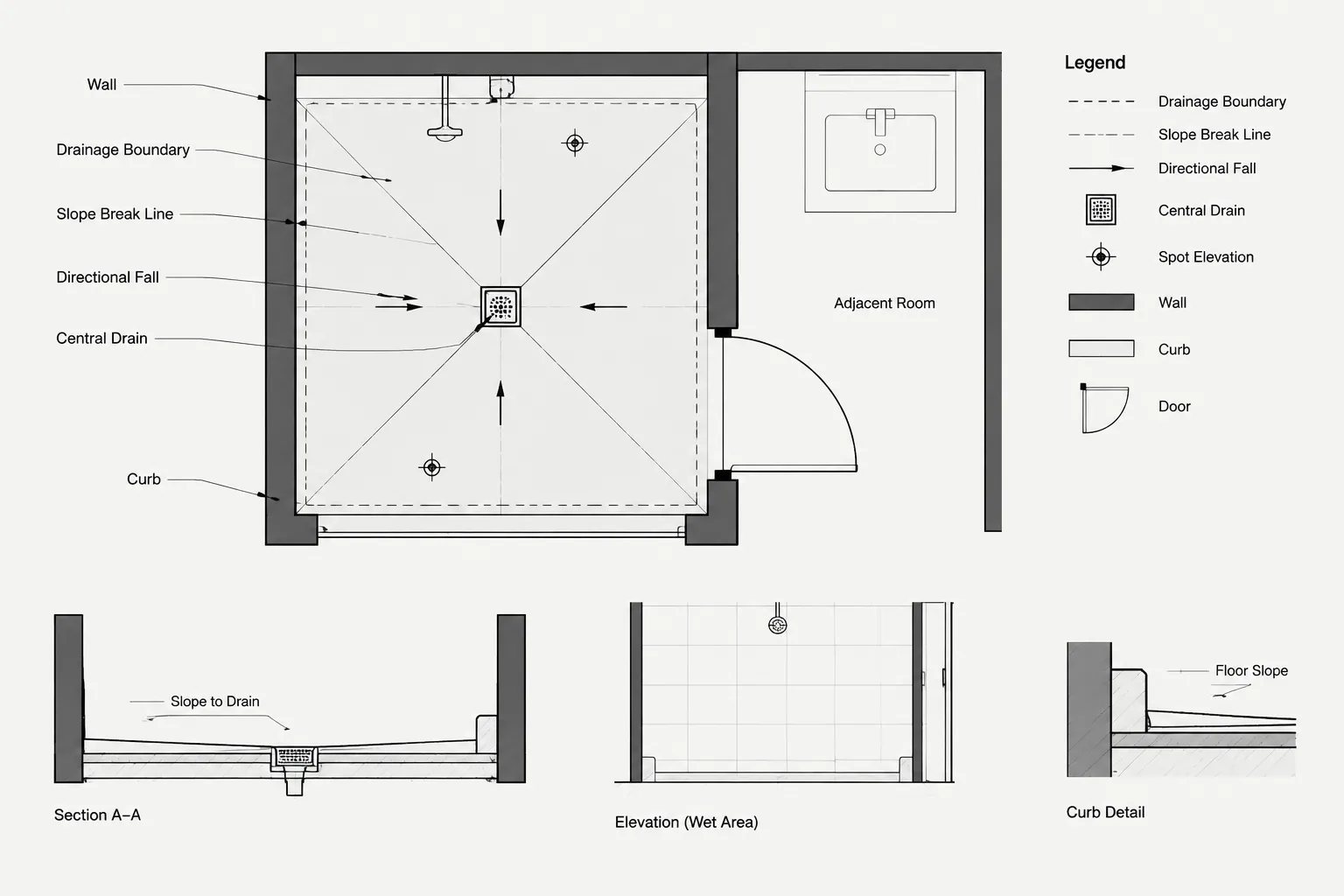
- Details isolate a specific junction, edge, attachment, transition, or construction condition.
If the purpose is unclear, the view often accumulates too many notes and dimensions. That is usually a sign that one drawing is being asked to perform several jobs.
Model at full size and control scale on the sheet
In a conventional architectural CAD workflow, building geometry is drawn at full size in model space using the project’s established drawing units. The plotted drawing scale is then controlled through paper-space viewports or an equivalent sheet-view workflow.
Avoid shrinking or enlarging model geometry merely to make it fit a sheet. Scaling the building model can create serious coordination problems, especially when the file is referenced into other drawings. Doors, furniture, consultant backgrounds, dimensions, hatches, and imported blocks may no longer align reliably.
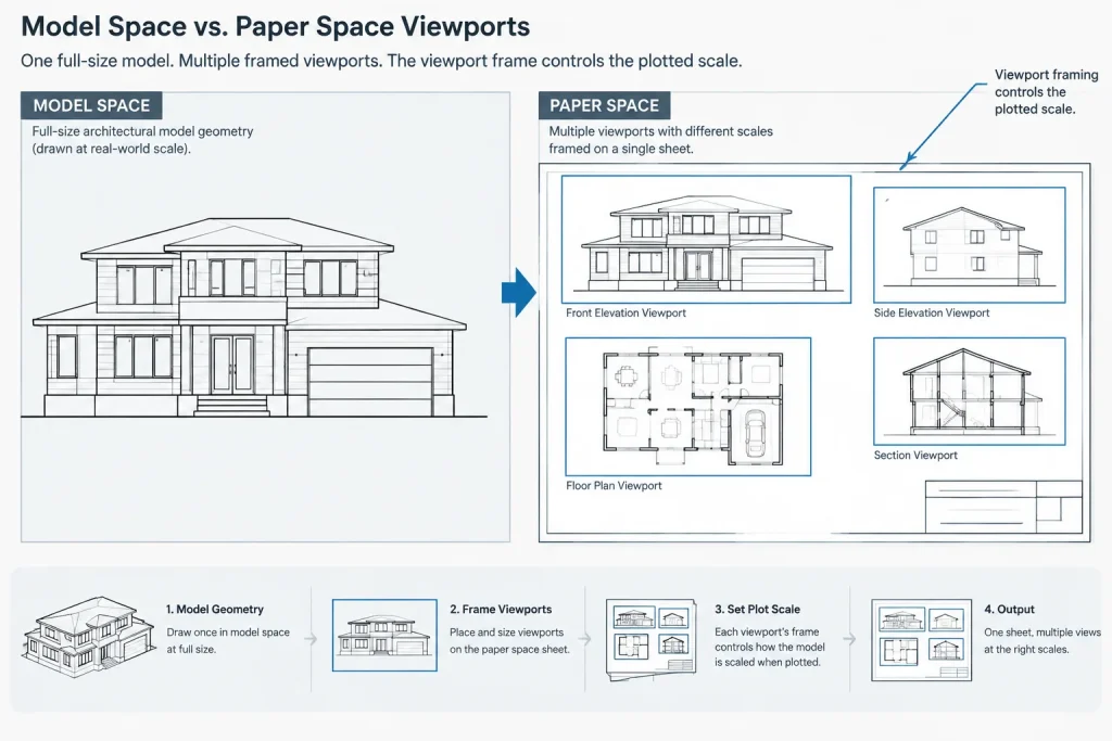
The sheet should function as a composed presentation of the model. Each viewport frames the required area and displays it at a deliberate scale. Once the viewport is set, lock it to reduce the risk of accidental zoom changes.
Evaluate the information density
Information density is the amount of visible geometry and annotation within a given sheet area. Two floor plans of similar physical size may require different drawing scales if one contains more rooms, equipment, dimensions, or irregular construction.
When evaluating a proposed scale, check whether the following elements remain distinguishable:
- Wall edges and openings
- Door swings and window locations
- Plumbing fixtures, casework, and fixed equipment
- Room names and tags
- Dimension strings and extension lines
- Grid bubbles, section marks, and elevation references
- Material patterns and overhead elements
- Revision graphics and keynotes
Geometry may technically fit while the annotation does not. For that reason, scale selection should be tested with representative notes, dimensions, symbols, and tags in place rather than with an empty plan.
Use a scale hierarchy across the drawing set
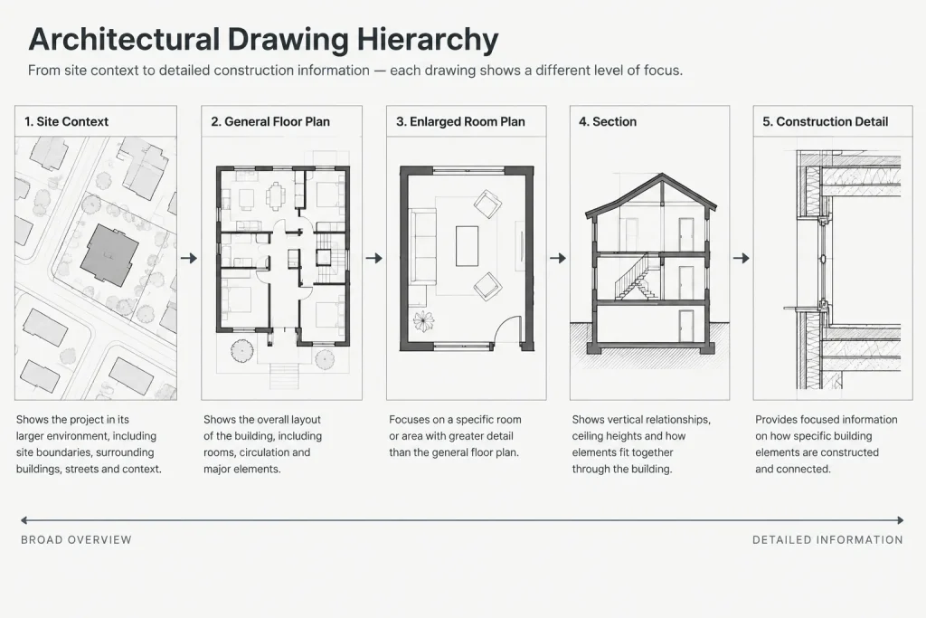
A coordinated drawing set usually moves from broad context to focused information. This creates a visual hierarchy that helps readers locate a condition and then find the view that explains it more fully.
| View type | Primary purpose | Typical content decision |
|---|---|---|
| Site or orientation view | Show context and overall relationships | Emphasize boundaries, access, major features, and building position |
| General plan | Explain the overall layout | Show major partitions, rooms, openings, references, and coordinated dimensions |
| Enlarged plan | Clarify a complex area | Add fixtures, equipment, clearances, detailed dimensions, and local notes |
| Elevation or section | Explain vertical organization | Show levels, openings, materials, major assemblies, and vertical dimensions |
| Detail | Resolve a specific condition | Limit the view to the components and notes needed for that condition |
This hierarchy does not mean repeating every item at every scale. Instead, assign information to the view where it can be read most effectively. A general plan may identify an enlarged area with a callout, while the enlargement carries the dimensions and notes that would overcrowd the parent view.
Coordinate annotation with viewport scale
Text, dimensions, leaders, symbols, and tags should have a consistent plotted appearance even when the model views use different scales. Depending on the office workflow, annotation may be placed in paper space, created with annotative behavior, or managed through scale-specific styles and layers.
Whichever method is used, apply it consistently. Mixing annotation methods without clear rules can cause duplicated notes, missing text, or symbols that plot at unintended sizes.
Check annotation in its plotted context
Do not judge text spacing only while zoomed into model space. Review the actual sheet layout and produce a test plot or PDF. Confirm that:
- Text is readable without dominating the drawing.
- Dimension strings do not merge with walls or adjacent notes.
- Callout heads remain clear and visually consistent.
- Leaders do not cross important geometry unnecessarily.
- Hatches do not become solid masses or distracting patterns.
- Lineweights preserve the intended foreground and background hierarchy.
Recognize when an enlarged view is needed
Increasing the scale of an entire plan is not always the best response to a congested area. If only one portion needs additional explanation, create an enlarged view and reference it from the general plan.
An enlargement is often useful when a local area contains several closely spaced fixtures, doors, accessories, level changes, or finish transitions. It can also separate specialized information from the general plan, allowing both views to remain legible.
Use a clear boundary or callout to define the enlarged area. Keep room names, wall geometry, grids, and orientation consistent between the parent view and enlargement so readers can recognize the relationship quickly. Avoid shifting elements merely to improve graphic spacing unless the drawing clearly indicates that the shift is diagrammatic.
Fit the sheet without sacrificing clarity
Sheet size, title-block space, drawing titles, notes, legends, and revision areas all affect the usable viewport area. Start sheet composition early enough that scale decisions do not become last-minute compromises.
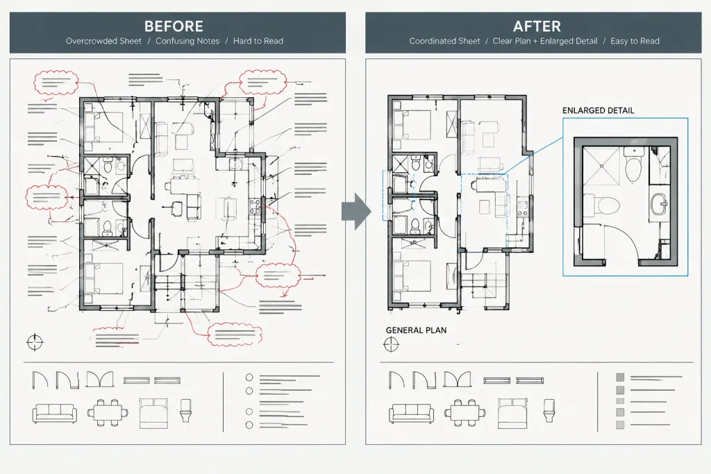
If a view does not fit, consider these options in order:
- Remove information that belongs on another drawing type.
- Crop unused surroundings while preserving orientation and reference points.
- Create an enlarged view for the congested portion.
- Split the view with coordinated match lines when the project format supports it.
- Reconsider the sheet arrangement or selected sheet format.
- Use a smaller scale only if the required information remains readable.
Reducing the scale should not be the automatic solution. A plan that fits but cannot be interpreted is not an effective drawing.
Keep related views consistent
Similar plans should normally follow a predictable scale strategy unless their content requires otherwise. For example, plans serving the same coordination purpose are easier to compare when they share a common visual scale and sheet organization.
Consistency is also important for repeated elevations, room enlargements, and typical details. When an exception is necessary, label the drawing scale clearly and verify that its annotation, lineweights, and reference symbols still match the rest of the set.
Do not assume a drawing is at scale merely because the viewport was configured correctly. Printed output may be reduced, enlarged, or fitted to a different page. Written dimensions and verified project information should govern; graphic scaling from a print should be treated cautiously.
A practical scale-selection workflow
- Define the view’s purpose. List the decisions that the drawing must communicate.
- Place the required model area on a sheet. Account for titles, notes, legends, and other views.
- Choose a candidate viewport scale. Frame the view without altering model geometry.
- Add representative annotation. Include typical dimensions, room tags, references, and notes.
- Review information density. Look for collisions, unreadable symbols, and excessive empty space.
- Create enlargements where needed. Move local detail out of the general view rather than forcing everything into one plan.
- Lock and label the viewport. Confirm that the displayed scale and drawing title agree.
- Test the output. Review a plotted sheet or PDF at its intended page size.
- Perform a coordination check. Compare scales, callouts, and view titles across the drawing set.
Final review checklist
- Is the model geometry still drawn at full size in the correct project units?
- Does the selected scale match the drawing’s purpose?
- Can all essential symbols, dimensions, and notes be read clearly?
- Would an enlarged view communicate any congested area more effectively?
- Are viewport scales locked and drawing titles accurate?
- Do related plans, elevations, sections, and details follow a logical hierarchy?
- Has the sheet been checked as a final plot or PDF rather than only in model space?
Effective architectural CAD drawing scales result from communication needs, not habit alone. By defining the purpose of each view, controlling scale at the sheet level, coordinating annotation, and testing the plotted output, drafters can create drawing sets that are easier to navigate and more reliable to use.
Treat scale selection as a coordination decision
Changing a viewport scale affects more than the amount of model geometry visible on the sheet. It can alter annotation spacing, crop boundaries, reference placement, hatch appearance, drawing balance, and the relationship between a parent view and its enlargements.
For that reason, a scale change should trigger a brief review of the entire view. Check the drawing title, viewport boundary, dimensions, tags, callouts, leaders, patterns, and adjacent sheet content rather than reviewing the geometry alone.
Test the view with a realistic sheet mockup
A useful scale test includes the information expected in the finished drawing. An undecorated model view can appear spacious even when the completed drawing will be crowded.
- Reserve space for the title block, drawing title, legends, notes, and revision information.
- Place representative dimensions, room identifiers, reference symbols, and leaders.
- Show typical hatches, overhead elements, fixtures, and fixed equipment.
- Confirm that crop boundaries retain enough context for orientation.
- Compare the view with related plans, elevations, sections, or details.
If annotation repeatedly obscures geometry, first decide whether some information belongs in another view. A larger scale can improve local readability, but it cannot correct an unclear information hierarchy.
Review the consequences of every scale change
Late scale changes can create coordination errors even when the viewport itself remains accurate. A drawing title may retain an outdated scale, a callout may no longer frame the intended area, or annotation may shift outside the visible boundary.
After changing scale, verify that the displayed view, written label, references, and final plot all agree. If sheets will be issued as PDFs, review them at the intended page size. A graphic scale may help readers recognize output resizing, but it does not replace written dimensions or verified project information.
Frequently asked questions about architectural drawing scales
Can one architectural sheet contain views at different scales?
Yes. A sheet may combine general views, enlargements, elevations, sections, or details when each view is clearly titled and its scale is identified. The composition should make the relationship between the views easy to understand.
Should scale be selected before annotation is added?
Select a candidate scale early, but validate it after adding representative annotation. Dimensions, tags, leaders, symbols, and hatches often reveal readability problems that are not visible in an empty model view.
Why can a plan look clear on screen but crowded when plotted?
Screen zoom can make text and closely spaced linework appear easier to read than they will be on a complete sheet. Plotting also reveals the effects of lineweight, hatch density, page reduction, and nearby drawings.
When should a drafter create an enlargement instead of changing the general plan scale?
Use an enlargement when congestion is concentrated in a limited area and the remainder of the general plan is already clear. The parent view can provide orientation and a callout, while the enlarged view carries the local dimensions and notes.
When is splitting a plan more useful than creating an enlargement?
A split plan can be appropriate when a broad drawing area cannot be presented legibly within the available sheet composition. An enlargement is generally better when only a localized condition requires additional information. Either method needs clear references and recognizable overlap or context.
Should model geometry be resized to match a desired plotted scale?
No. In the workflow described here, project geometry remains full size in the established model units. The viewport or equivalent sheet-view setup controls how that geometry is presented on the sheet.