Overlapping notes, hatches, symbols, and reference linework are common in architectural CAD files. The challenge is not simply making the sheet look clean; it is preserving important geometry while establishing a readable and maintainable graphic hierarchy.
This guide explains how to choose between text background masks, wipeouts, draw-order changes, hatch edits, and layer controls. It also highlights the coordination and output checks needed before relying on masked content in a drawing set.
Architectural drawings often contain overlapping information: room tags sit over floor patterns, notes cross wall lines, equipment symbols cover casework, and enlarged details combine dense hatches with dimensions. CAD masking tools can make these areas easier to read, but careless masking can also conceal geometry, create plotting problems, and make coordination errors harder to detect.
A reliable architectural CAD masking workflow uses the least disruptive tool necessary. Text background masks are usually appropriate for annotation, while wipeouts are better reserved for controlled graphic situations. Draw order then determines which objects remain visible. None of these tools should be used as a substitute for cleaning up geometry, organizing layers, or coordinating the drawing.
What masking does in a CAD drawing
A mask visually covers objects behind another object without necessarily deleting or trimming the underlying geometry. This can preserve the source linework while creating a clear area around a note, symbol, or block.
Common architectural uses include:
- Clearing hatch patterns behind room names and keynotes.
- Improving the readability of multileader text over dense details.
- Hiding wall or floor lines beneath selected equipment symbols.
- Creating clean diagrammatic symbols without editing the background plan.
- Separating overlapping graphics within composite blocks.
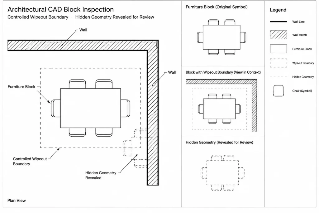
The important distinction is that hidden geometry still exists. It may remain selectable, appear in another viewport, or become visible when the mask is moved or deleted. A clean-looking plot therefore does not automatically indicate a clean or coordinated model-space drawing.
Choose the correct visibility tool
| Tool or method | Best use | Main caution |
|---|---|---|
| Text background mask | Notes, labels, room names, and multileader content | An oversized mask can interrupt nearby linework |
| Wipeout | Controlled blank areas inside symbols, blocks, or diagrammatic graphics | Its boundary and display order require careful management |
| Draw order | Placing text, symbols, hatches, and masks in the intended visual sequence | Complex nested blocks may not behave as expected without testing |
| Hatch boundary adjustment | Removing unnecessary patterning around important information | Boundary edits require maintenance when the design changes |
| Layer control | Separating information by view, phase, or drawing purpose | Turning off a layer may hide more information than intended |
| Trimming or editing geometry | Correcting linework that should not exist in the final drawing | Do not alter referenced backgrounds merely to improve one sheet |
Start with the most specific option. If only a note needs clearance, mask the note rather than placing a large wipeout across the plan. If a line is genuinely incorrect, fix the line instead of hiding it.
Use text background masks for annotation
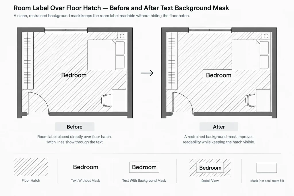
Background masks associated with text are generally easier to manage than independent wipeout objects because the mask moves with the annotation. They are useful for multiline text, leaders, keynote descriptions, and labels placed over hatches or linework.
Keep the clearance visually restrained
The blank space around text should be large enough to separate the characters from the background but not so large that it breaks walls, grids, or dimensions unnecessarily. Review the result at the intended plotted scale rather than judging only from a close model-space view.
When a label crosses important geometry, first consider moving the label into a less congested area. Masking should improve an already organized annotation layout, not compensate for poor placement.
Check the text object, not only the appearance
Two notes may look similar while using different text objects, styles, or masking settings. Standardize how annotation is created so future edits remain predictable. If notes are copied from outside files, inspect their style, layer, annotative behavior where applicable, and mask settings before adding them to the project library.
Reserve wipeouts for controlled graphic conditions
A wipeout is an independent masking object with a boundary. It can be useful where a symbol needs an opaque interior or where several types of geometry must be hidden beneath one defined shape. Typical examples include diagrammatic equipment blocks, north arrows with opaque centers, and symbols placed over patterned backgrounds.
Wipeouts should be used cautiously in floor plans and details. A large wipeout can conceal door swings, wall openings, dimensions, or consultant information while leaving no obvious indication that the underlying content is present.
Build wipeouts into blocks deliberately
If a block needs a wipeout, decide whether the mask belongs inside the block definition or should remain separate. An internal mask is useful when every instance should behave consistently. A separate mask may be appropriate when visibility depends on a specific view, but it creates more objects to manage.
Test masked blocks against lines, polylines, hatches, external references, and other blocks. Also test rotated and mirrored instances. The symbol should remain legible without hiding more of the background than intended.
Manage wipeout frames consciously
Wipeout boundaries can be helpful during editing because they reveal the extent of hidden information. For plotted output, the desired frame display depends on the drawing convention and output setup. Do not assume the screen display guarantees the same plotted result. Include frame visibility in the pre-issue review.
Establish a clear draw-order hierarchy
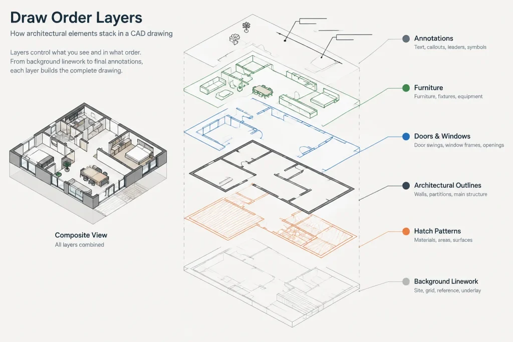
Draw order controls which overlapping objects appear in front. A practical architectural hierarchy often places broad background information first and critical annotation last. The exact arrangement will vary, but the following sequence provides a useful starting concept:
- Reference and background linework.
- Large-area poche and hatch patterns.
- Primary architectural outlines and cut elements.
- Fixtures, furniture, equipment, and symbols.
- Masks associated with annotation or symbols.
- Dimensions, tags, leaders, and notes.
This is not a universal standard. Some symbols must sit below dimensions, while certain hatches should appear behind all linework. The objective is to define a repeatable office or project convention rather than correcting individual overlaps randomly.
Watch for nested content and external references
Draw order can become difficult when linework is nested inside blocks or external references. Bringing a top-level block forward does not necessarily resolve every internal overlap. Edit the block definition if its internal objects are arranged incorrectly.
A host drawing should not depend on masks to repair poorly organized referenced files. Correct source files where practical, then reload and review the references. When source editing is not appropriate, use viewport and layer controls before introducing broad masks.
A practical masking workflow
- Identify the real problem. Determine whether the conflict comes from incorrect geometry, excessive hatching, poor annotation placement, or genuine overlap.
- Try relocation first. Move a note, tag, or dimension to a clearer location when doing so preserves its relationship to the referenced element.
- Reduce unnecessary graphics. Adjust hatch boundaries, symbol detail, or layer visibility if the background is more complex than the drawing requires.
- Apply the smallest suitable mask. Prefer an object-based text mask for annotation. Use a wipeout only when a defined graphic area must remain opaque.
- Set draw order. Place the mask behind the information it supports but ahead of the objects it is intended to cover.
- Inspect hidden content. Temporarily expose mask boundaries or move a copy of the mask to confirm that important geometry has not been concealed.
- Test representative output. Review the drawing in the target sheet viewport and inspect a plotted or exported file.
- Repeat after revisions. Recheck masked areas when walls, room layouts, hatches, references, or annotation positions change.
Common masking mistakes
Using one large wipeout to clean an entire area
This produces a tidy image quickly but can conceal unrelated objects and future design changes. Divide the problem into smaller areas or correct the underlying linework.
Masking coordination conflicts
A mask should never be used to make intersecting fixtures, doors, structural elements, or building systems appear coordinated. Resolve the conflict first, then use masking only for graphic clarity.
Ignoring the final sheet scale
A mask that looks subtle while zoomed in may create a conspicuous blank patch on the plotted sheet. Conversely, a narrow mask may not provide enough clearance at a reduced scale.
Depending on color alone
An object that appears to blend into the drawing background on screen may plot differently. Use actual masking behavior where an opaque result is required, and verify the output.
Forgetting masks inside downloaded blocks
Third-party blocks may contain wipeouts that extend beyond visible geometry or cover nearby objects unexpectedly. Inspect the block definition, boundary size, layers, and draw order before using it in a project.
Pre-issue review checklist
- Confirm that notes and tags remain readable at the intended sheet scale.
- Check that masks do not interrupt critical wall, grid, section, or dimension graphics.
- Inspect masked blocks in rotated, mirrored, and repeated conditions.
- Review wipeout frame visibility in both the working file and final output.
- Check areas where hatches, external references, and nested blocks overlap.
- Look for hidden objects that should have been deleted or corrected instead.
- Open the exported deliverable and compare it with the CAD sheet view.
Use masking as a finishing tool, not a repair strategy
Effective architectural CAD masking is selective and easy to understand. Text masks support annotation, wipeouts serve limited graphic purposes, and draw order creates a consistent visual hierarchy. When masks become numerous, oversized, or difficult to explain, they usually indicate a deeper issue with layers, block construction, hatch boundaries, or drawing organization.
Keep masks small, inspect what they hide, and verify every important output format. The goal is not merely to produce a clean screen image, but to maintain a drawing that remains readable, coordinated, and editable throughout the project.
Diagnosing a masking problem
When an overlap returns after editing, determine whether the mask itself failed or whether the surrounding drawing changed. A revised hatch, replaced reference, edited block, or relocated annotation can alter the visible result even when the masking object remains intact.
Unexpected linework appears through a symbol
Inspect the symbol definition and its internal object order before repeatedly bringing the entire block forward. The visible conflict may come from geometry nested inside the block rather than from the position of the block in the host drawing.
A blank area is larger than expected
Temporarily expose the masking boundary and compare it with the visible text or symbol. Oversized wipeouts are especially difficult to recognize when their frames are hidden. Also check for overlapping masks from copied or nested content.
The CAD view and exported sheet do not match
Review the actual sheet viewport and exported deliverable rather than relying on model-space appearance. Frame display, object order, hatches, references, and output processing can interact differently than expected. A representative output check is more reliable than an isolated on-screen inspection.
Managing masks in a shared CAD workflow
Masking behavior should be understandable to anyone who edits the file. Place masks on intentional layers, use consistent annotation settings, and avoid unexplained patches that another drafter may mistake for expendable geometry. When a block includes an internal wipeout, document that behavior in the block library or project drafting guidance.
During cleanup, do not delete a mask solely because it appears unnecessary in the current view. First inspect the content behind it and test relevant sheet conditions. The object may support another viewport, symbol state, or background arrangement.
A useful review principle
Every mask should have a clear graphic purpose and a limited area of effect. If removing a mask reveals a coordination problem, correct the problem rather than restoring the mask to conceal it. If removing it only reduces annotation clarity, the mask is probably serving an appropriate drafting function.
Frequently asked questions
Should text use a background mask or a separate wipeout?
Use a text-associated background mask when the goal is to clear linework directly behind annotation. Because it remains associated with the text object, it is generally easier to move and maintain. Reserve a separate wipeout for a controlled graphic area that is not adequately handled by the annotation object.
Can draw order replace a mask?
Draw order determines which object appears in front, but it does not create blank clearance around text or symbols. It can place annotation above a hatch, yet the hatch may still remain visible between and around the characters. A mask may still be needed when visual separation is required.
Why does bringing a block to the front not fix an overlap?
The conflicting objects may be nested inside the block, another block, or an external reference. Top-level draw order does not necessarily correct the order of objects within nested content. Inspect the relevant definition and test the result in the host drawing.
Should wipeout frames remain visible?
Visible boundaries can help during editing because they show what the wipeout covers. The preferred appearance for issued output depends on the drawing convention and output setup. Check both the working view and final exported file rather than assuming they will match.
How can hidden geometry be checked safely?
Expose mask boundaries, temporarily relocate a copy, or inspect the underlying content in a controlled working view. Confirm that the mask is covering only intentional background graphics and not hiding openings, dimensions, reference changes, or coordination conflicts.
Are wipeouts appropriate for downloaded CAD blocks?
They may be useful, but downloaded blocks should be inspected before project use. Review the block definition, masking boundary, layers, nested content, and draw order to ensure that the block does not obscure nearby drawing information.